

Valor 347 Helmsley Installation And Owner's Manual
© GDC Group Limited 2014.
08/52376/0
Model 347
RADIANT / CONVECTOR GAS FIRE
Fitted with the following fascia
Helmsley
INSTALLER: Please leave this guide with the owner
INSTALLATION AND OWNER GUIDE
We trust that this guide gives
sufficient details to enable this
appliance to be installed, operated
and maintained satisfactorily.
However, if further information is
required, our
Valor Fires Technical Helpline will
be pleased to help.
Telephone 0844 879 35 88 (National
call rates apply in the United
Kingdom).
In the Republic of Ireland
Telephone 01 842 8222.
GDC Group Limited
All rights reserved. No part of this publication may be reproduced in any material form
(including photocopying), stored in any medium by electronic means (including in any
retrieval system or database) or transmitted, in any form or by any means, whether
electronic, mechanical, recording or otherwise, without the prior written permission of
the copyright owner.
Applications for the copyright owner's permission to reproduce any part of this
publication should be made, giving details of the proposed use, to the following
address: The Company Secretary, GDC Group Ltd., Millbrook House, Hedge End,
Southampton, SO30 2DF.
Warning: Any person who does any unauthorised act in relation to a copyright work
may be liable to criminal prosecution and civil claims for damages.
Valor Fires, GDC Group Ltd., Millbrook House, Hedge End, Southampton, SO30 2DF
www.valor.co.uk
Because our policy is one of constant development and improvement, details may vary
slightly from those given in this publication.
Page 2
© GDC Group Limited 2014.
THIS APPLIANCE IS FOR USE WITH NATURAL GAS (G20).
UNDER NO CIRCUMSTANCES IS THIS FIRE TO BE CONVERTED TO LPG.
AN LPG KIT DOES NOT EXIST FOR THIS GAS FIRE.
THIS APPLIANCE IS SUITABLE ONLY FOR INSTALLATION IN THE UNITED
KINGDOM (GB) AND THE REPUBLIC OF IRELAND (IE).
Safety First.
Valor Fires fires are CE Approved and designed to meet the appropriate British
Standards and Safety Marks.
Quality and Excellence.
All Valor Fires fires are manufactured to the highest standards of quality and
excellence and are manufactured under a BS EN ISO 9001 quality system accepted
by the British Standards Institute.
The Highest Standards
Valor Fires is a member of SBGI and HHIC (Heating and Hot water Industry Council)
that work to ensure high standards of safety, quality and performance.
Careful Installation
This gas fire must be installed by a competent GAS SAFE REGISTER engineer
(CORGI or GAS SAFE REGISTER engineer outside of UK) in accordance with our
installer guide and should not be fitted directly on to a carpet or floor of combustible
material.
Page 3
© GDC Group Limited 2014.

Page 4
© GDC Group Limited 2014.
INSTALLER GUIDE
FOR OWNER GUIDE SEE PAGES 29 TO 44
INSTALLER GUIDE

INSTALLER GUIDE
CONTENTS
Section Heading Page
INSTALLER GUIDE 4 - 28
OWNER GUIDE 29 - 43
1. SAFETY 7
2. LIST OF ACCESSORIES 7
3. APPLIANCE DATA AND EFFICIENCY 8
3.1 Appliance data. 8
3.2 Efficiency. 8
4. GENERAL INSTALLATION REQUIREMENTS 9
4.1 Regulations, Standards and Law. 9
4.2 Ventilation. 10
4.3 The Atmosphere sensing device (ASD). 10
4.4 Room considerations. 10
4.5 Chimney preparation. 11
4.6 Fireplace preparation. 11
4.7 Fireplace clearances. 12
4.8 The Flue spigot. 13
4.9. The hearth. 14
4.10 Installation options. 14
4.10.1 Conventional fireplace. 14
4.10.2 Precast flues. 14
4.10.3 Wall mounting to conventional or pre-cast flues. 15
4.10.4 Metal flue box. 16
4.11 Flues. 16
5. PRE-INSTALLATION PREPARATION 17
5.1 Unpacking. 17
5.2 Appliance preparation. 17
5.3 Fitting the battery to electronic ignition model 18
5.4 Checking the ignition 18
5.4.1 Electronic ignition 18
5.5 Fireplace flue pull. 18
5.6 Fit the closure plate. 19
6. APPLIANCE INSTALLATION 20
6.1 Installing to a hearth. 20
6.2 Wall mounting. 20
6.3 Gas supply connection. 20
6.4 Radiants installation. 20
6.5 Flue restrictor adjustment. 21
© GDC Group Limited 2014.
Continued on next page
Page 5

INSTALLER GUIDE
CONTENTS (Continued)
Section Heading Page
7. CONTROL AND PRESSURE CHECKS 22
7.1 Check control settings. 22
7.2 Flame supervision and spillage monitoring system. 22
7.3 Check reference pressure. 23
8. FASCIA FITTING 23
9. SPILLAGE CHECK 24
10. FINAL REVIEW 25
11. SERVICING AND PARTS REPLACEMENT 26
11.1 To replace radiant(s). 26
11.2 To remove the fascia. 27
11.3 To replace the pilot unit. 27
11.4 To remove the complete burner module, pipes and pilot. 28
11.5 To grease the gas tap. 28
© GDC Group Limited 2014.
Page 6

INSTALLER GUIDE
1. SAFETY
Installer
Before continuing any further with the installation of this appliance please read the
following guide to manual handling:
- The lifting weight of this appliance is
- One person should be sufficient to lift the fire. If for any reason this weight is
considered too heavy then obtain assistance.
- When lifting always keep your back straight. Bend your legs and not your back.
- Avoid twisting at the waist. It is better to reposition your feet.
- Avoid upper body / top heavy bending. Do not lean forward or sideways whilst
handling the fire.
- Always grip with the palm of the hand. Do not use the tips of fingers for support.
- Always keep the fire as close to the body as possible. This will minimise the
cantilever action.
- Use gloves to provide additional grip.
- Always use assistance if required.
This appliance does not contain any component manufactured from asbestos or
asbestos related products.
15.0 kg.
2. LIST OF ACCESSORIES
Description Part number
Spigot extension 0595191
© GDC Group Limited 2014.
Page 7
INSTALLER GUIDE
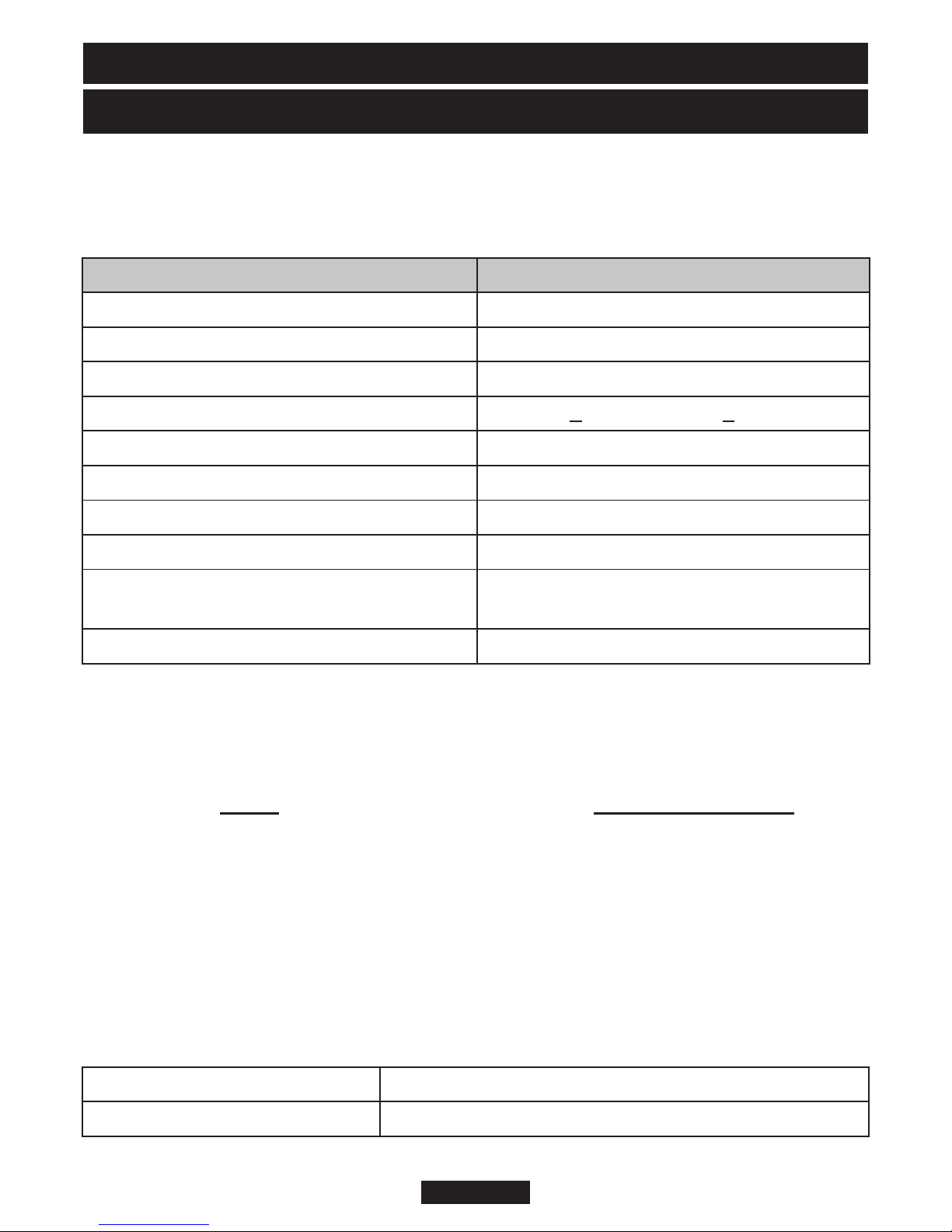
3. APPLIANCE DATA AND EFFICIENCY
3.1 Appliance data.
The appliance information label is on the inner face of the back panel at the lower left
hand side. It is visible when the fascia is removed.
Gas Natural (G20)
Inlet Pressure 20mbar
Input - Max. (Gross) 5.5 kW (18,767 Btu/h)
Input - Min. (Gross) 1.57W (5,357 Btu/h)
Burner Test Pressure (Cold) 17.95 + 0.75mbar (7.2 + 0.3in w.g.)
Gas Connection 8mm pipe
Burner Injector - Upper (Centre Radiants) Cat 28 - 170
Burner Injector - Lower (Outer Radiants) Cat 28 - 170
Pilot & Atmosphere Sensing Device OPNG9093
Ignition Electronic (Mounted on gas valve)
Aeration Non-adjustable
3.2 Efficiency.
The efficiency of this appliance has been measured as specified in BS 7977 - 1 and
the result is as below:
Model
347 Helmsley 73
The gross calorific value of the fuel has been used for this efficiency calculation. The
test data from which it has been calculated has been certified by Advantica
Certification services (0087). The efficiency value may be used in the UK
Government's Standard Assessment Procedure (SAP) for energy rating of dwellings.
The conversion of net efficiency to gross was achieved by multiplying the net
efficiency by the following conversion factor from Table E3 of SAP 2005, rounding
down to the nearest whole number.
Efficiency % (Gross)
Gas Conversion factor from net to gross efficiency
Natural Gas 0.901
© GDC Group Limited 2014.
Page 8

INSTALLER GUIDE
4. GENERAL INSTALLATION REQUIREMENTS
4.1 Regulations, Standards and Law.
The installation must be in accordance with these instructions.
For the user’s protection, in the United Kingdom it is the law that all gas appliances
are installed by competent persons in accordance with the current edition of the Gas
Safety (Installation and Use) Regulations. Failure to install the appliance correctly
could lead to prosecution. GAS SAFE REGISTER and CORGI require their members
to work to recognised standards.
In the United Kingdom the installation must also be in accordance with:
- All the relevant parts of local regulations.
- All relevant codes of practice.
- The relevant parts of the current editions of the following British Standards:-
BS 715 - Specification for metal flue boxes for gas-fired appliances not
exceeding 20kW.
BS EN 1806 - Chimneys – Clay/ceramic flue blocks.
BS 5440 Part 1 - Flueing and ventilation for gas appliances of rated input not
exceeding 70 kW net (1st, 2nd and 3rd family gases).
Specification for installation of gas appliances to chimneys and
for maintenance of chimneys.
BS 5440 Part 2 - Installation and maintenance of flues and ventilation for gas
appliances of rated input not exceeding 70 kW net (1st, 2nd
and 3rd family gases).
BS 6891 - Installation of low pressure gas pipework of up to 35mm (R1
¼) in domestic premises (2nd family gas) - specification.
BS 1251 - Fireplace components.
BS EN 1856 Part 1 - Chimneys – Requirements for metal chimneys.
BS 5871 Part 1 - Specification for the installation and maintenance of gas fires,
convector heaters, fire/back boilers and decorative fuel effect
gas appliances. Gas fires, convector heaters, fire/back boilers
and heating stoves (2nd and 3rd family gases).
BS EN 1858 - Chimneys – Components – Concrete flue blocks.
BS EN 15287 Part 1 - Chimneys. Design, installation and commissioning of
chimneys. Chimneys for non-room sealed heating appliances.
- In England and Wales, the current edition of the Building Regulations issued by
the Department of the Environment and the Welsh Office.
- In Scotland, the current edition of the Building Standards (Scotland) Regulations
issued by the Scottish Executive.
- In Northern Ireland, the current edition of the Building regulations (Northern
Ireland) issued by the Department of the Environment for Northern Ireland.
- In the Republic of Ireland the installation must be carried out by a competent
person and installed in accordance with:
© GDC Group Limited 2014.
Page 9

INSTALLER GUIDE
a) The current edition of IS 813 “Domestic gas installations”.
b) All relevant national and local rules in force.
c) The current building regulations.
Where no specific instructions are given, reference should be made to the relevant
British Standard Code of Practice.
4.2 Ventilation.
Normal adventitious ventilation is usually sufficient to satisfy the ventilation
requirements of this appliance. In GB reference should be made to BS 5440 Part 2
and in IE reference should be made to the current edition of IS 813 “Domestic gas
Installations” which makes clear the conditions that must be met to demonstrate that
sufficient ventilation is available.
4.3 The Atmosphere sensing device (ASD).
The appliance is fitted with an A.S.D (Atmosphere sensing device). If the appliance
closes down after a period of operation for no apparent reason, the consumer should
be informed to stop using the appliance until the installation and appliance have been
thoroughly checked. The A.S.D will shut the appliance down if an unacceptable
amount of harmful products of combustion accumulate. Under no circumstances
should the A.S.D be altered or bypassed in any way. Only genuine manufacturer’s
replacement parts should be fitted.
4.4 Room considerations.
4.4.1 The appliance must not be installed in any room, which contains a bath, or
shower or where steam is regularly present.
4.4.2 An extractor fan may only be used in the same room as this appliance, or in
any area from which ventilation for the appliance is taken, if it does not affect the safe
performance of the appliance. Note the spillage test requirements detailed further on
in this manual. If the fan is likely to affect the appliance, the appliance must not be
installed unless the fan is permanently disconnected.
4.4.3 Note that soft wall coverings (e.g. embossed vinyl, etc.) are easily affected by
heat. They may scorch or become discoloured when close to a heating appliance.
Please bear this in mind when installing.
4.5 Chimney preparation.
4.5.1 If the appliance is intended to be installed to a chimney that was previously
used for solid fuel, the flue must be swept clean prior to installation. All flues should
be inspected for soundness and freedom from blockages.
4.5.2 Any chimney dampers or restrictors should be removed. If removal is not
possible they must be fixed in the open position.
© GDC Group Limited 2014.
Page 10
INSTALLER GUIDE
Figure 1. Area to be free of combustible
cladding
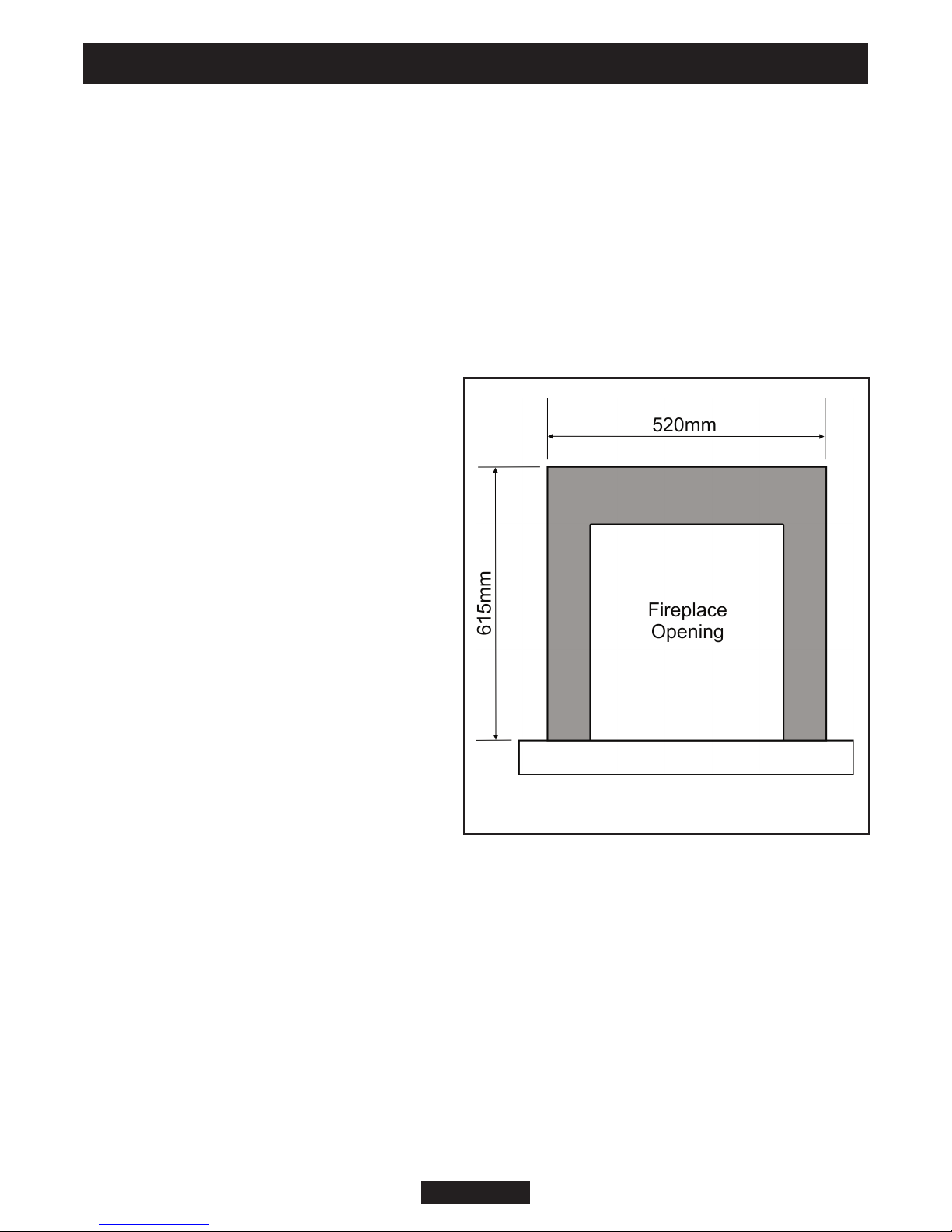
4.6 Fireplace preparation.
4.6.1 The appliance can be fitted to a purpose made proprietary class “O” 150°C
surround.
4.6.2 If the fireplace opening is an underfloor draught type, it must be sealed to stop
any draughts.
4.6.3 The front of the fireplace should be flat over an area sufficient to ensure a good
seal with the closure plate. The flat surface should extend for a height equal to that of
the closure plate plus 20mm and for a width equal to that of the closure plate plus
40mm.
4.6.4 If the fire is to be fitted against a
wall with combustible cladding, the
cladding must be removed from the area
shown in figure 1.
4.6.5 The space between the fireplace
front face and the back of the fascia
must not be filled in.
4.6.6 If the fireplace opening is greater
than the acceptable dimensions given in
this guide, do not use the back of a fire
surround or marble to reduce the
opening. This may cause cracking of the
surround back or marble.
© GDC Group Limited 2014.
Page 11
INSTALLER GUIDE
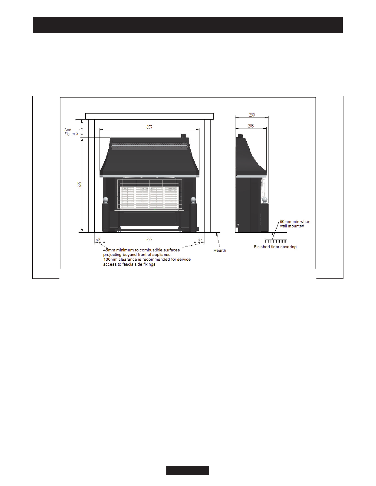
Figure 2. Dimensions and clearances
4.7 Fireplace clearances.
4.7.1 The minimum allowable distance from the outside of the appliance fascia to a
corner wall having combustible material or any other combustible surface which
projects beyond the front of the appliance is 48mm at either side (See figure 2).
Although no side clearance is necessary to non-combustible surfaces we recommend
a 100mm clearance for service access to the fascia side fixings.
4.7.2 Allow a minimum clearance of 95mm from the top surface of the appliance
fascia to the underside of any shelf whether it is made from combustible or non-
combustible materials. This clearance is necessary to allow the fascia to be lifted off
for servicing and also allows the owner sufficient access to operate the control knob.
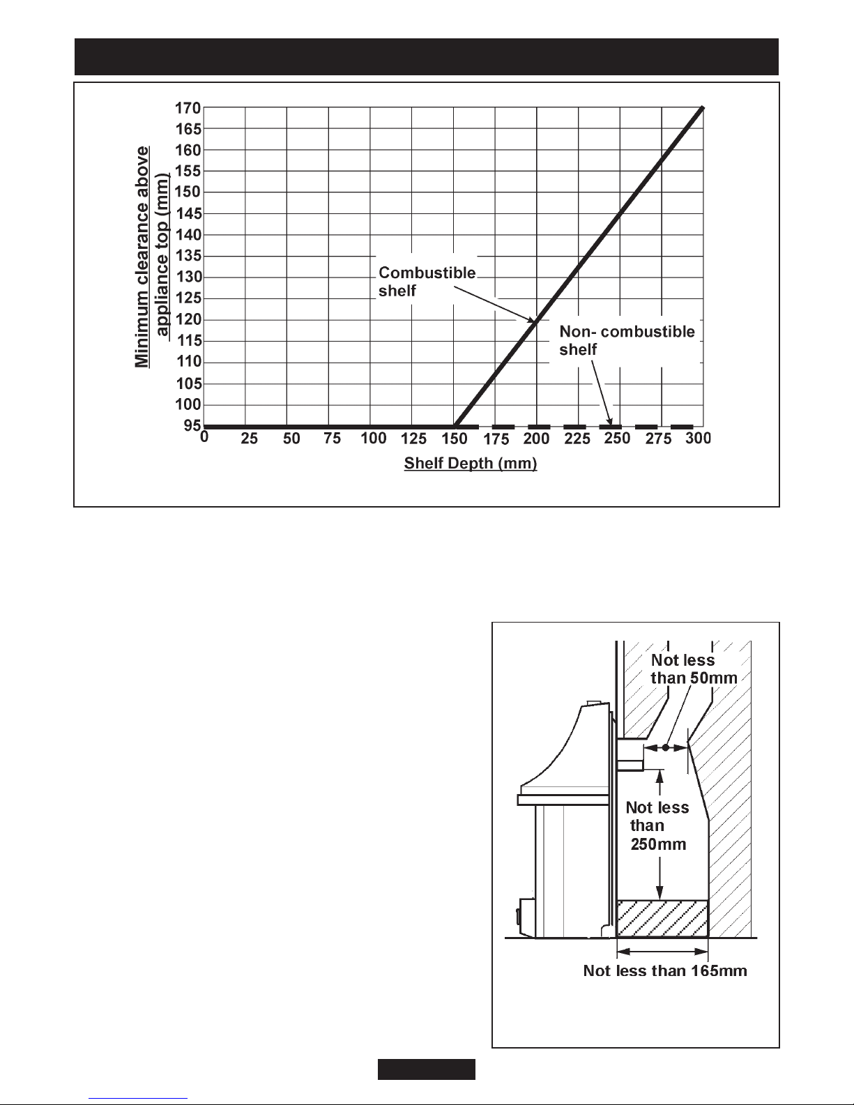
For a shelf made from wood or other combustible materials deeper than 150mm,
the minimum clearance must be as below.
• For a shelf up to 150mm deep: Minimum clearance = 95mm.
• For a shelf deeper than 150mm: 95mm + 12.5mm for every 25mm depth over
150mm (See Figure 3).
© GDC Group Limited 2014.
Page 12
INSTALLER GUIDE
Figure 3. Shelf clearances
Figure 4. Conventional fireplace
catchment space.
4.8 The Flue spigot.
4.8.1 The flue spigot and any spigot extension
must be capable of passing through the closure
plate by at least 38mm with a minimum clearance
of 50mm between its open end and the nearest
obstruction.
There must also be a minimum clearance of
165mm between the back of the closure plate and
the back of the catchment space.
On conventional flues the catchment space below
the flue spigot must extend at least 250mm
downwards measured from the bottom of the flue
spigot (See figure 4).
4.8.2 A spigot extension is available (Valor Fires
part number 0595191). When fitted this shall
extend through the closure plate for at least 38mm
and have a minimum clearance of 50mm from the
end to any surface.
© GDC Group Limited 2014.
Page 13
INSTALLER GUIDE
4.9. The hearth.
The appliance must be mounted on a non-combustible hearth except when the
conditions in section 4.10.3 are met (N.B. conglomerate marble hearths are
considered as non-combustible). The hearth must be at least 680mm wide x 300mm
deep. The hearth material must be at least 12mm thick. The periphery of the hearth
(or fender) should be at least 50mm above floor level to discourage the placing of
carpets or rugs over it.
4.10 Installation options.
In the United Kingdom, as supplied, this appliance can be installed in the following
situations:
4.10.1 Conventional fireplace.
The fireplace opening must be within the following dimensions:
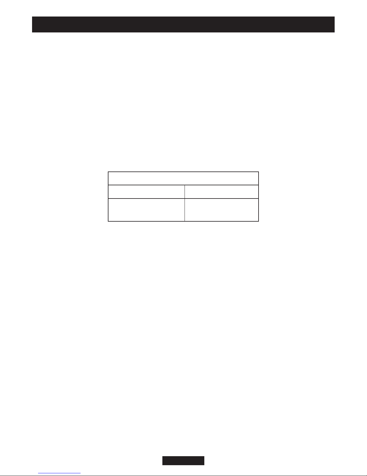
Conventional Fireplace
Width Height
Max. 440mm
Min. 305mm
*
The total height of the closure plate is 660mm and will accommodate a maximum
opening height of 650mm (This allows a 10mm overhang). Heights above
mm (Inclusive of sealing tape) will leave the sealing tape and closure plate visible
620
above the appliance.
4.10.2 Precast flues.
The appliance can be installed to a fireplace that has a properly constructed precast
concrete or clay flue block system conforming to BS EN 1858 or BS1289. The
appliance is suitable for installations conforming to older versions of BS1289 as well
as the current standards. The flue blocks must have a minimum width not less than
63mm and a cross-sectional area not less than 13,000mm2. Older editions of BS1289
required a cross-sectional area of 13,000mm2. The current revision of the standard
requires 16,500mm2. This appliance is suitable in both cases.
The chimney should be one or two storeys high but not less than 3m vertical height
and be correctly terminated. No mortar fangs between the blocks should be extruded
into the flue way. If raking blocks are used, they must be fitted in accordance with the
manufacturer’s instructions. Mortar must not be allowed to drop down and accumulate
in the raked positions.
Max. 610mm
Min. 525mm
*
© GDC Group Limited 2014.
Page 14
 Loading...