

CONTOUR
MODEL 3290 - TEAK FINISH
&
SILHOUETTE
MODEL 3291 - MAHOGANY FINISH
MODEL 3297 - BLACK ASH FINISH
RADIANT / CONVECTOR GA S FIRES
INSTALLATION & SERVICING INSTRUCTIONS
THIS APPLIANCE IS FOR USE WI TH NATURAL GAS (G20) AT A
SUPPLY PRESSURE OF 20mbar (8in w. g.)
THIS APPLIANCE IS FOR US E IN THE UNITED KINGDOM (GB)
AND THE REPUBLIC OF IRELAND (IE) ONLY
INSTALLER: Please leave these instruc tions with the owner
600A591/04
2
LIST OF CONTENTS
Page
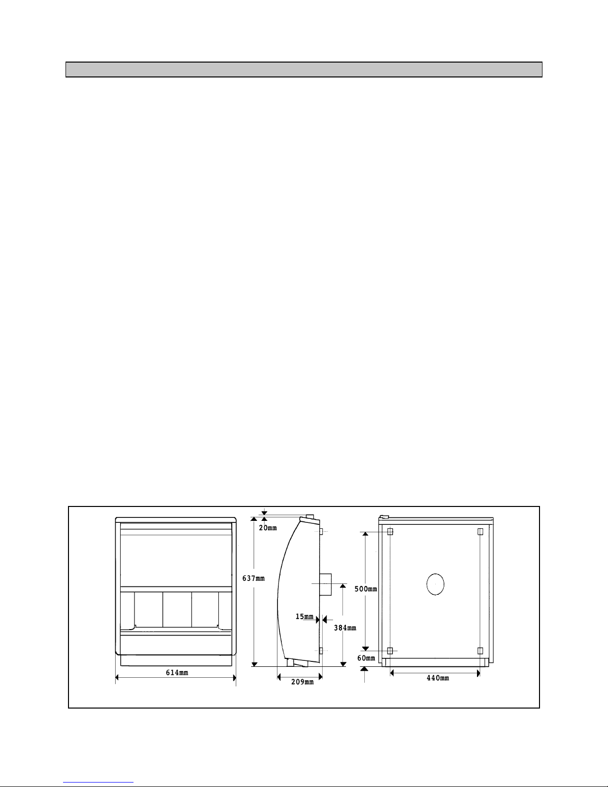
Appliance dimensions 2
Appliance data 3
General installation requirem ents 3
Unpacking & pre-installation preparat io n 5
• Carton contents
5
• Fireplace flue pull check
5
• Preparing applianc e for installation
5
• Closure plate fitting
6
Appliance installation 7
• Hearth in s tallation
7
• Wall mount in g
7
• Gas supply connection
7
• Radiants fitting
7
Operating checks 7
• Control settings check
7
• Spillage check
7
• Final assem b ly
8
Final review 8
Servicing & p art s replacement 9
• Radiants re placement
9
• Outer case removal
9
• Pilot unit re p lac e ment
9
• Burner, gas tap & pilot removal
9
• Gas tap or injector replacement
9
• Piezo ge n erator replacement
9
• Gas tap greasing
10
• Complete fire removal
10
Short list of spares 10
Figure 1 Appliance dimensions

3
1. APPLIANCE DATA
This appliance does cont a in no t a ny co mpo ne nt ma nufa ct ur ed
from asbestos or asbestos r elated products.
The appliance dat a label is on the inner fa ce of the me tal cas e
at the left side. It is visible when the outer case is removed.
Gas: Natural (G20)
Inlet pressure: 20mbar (8in. w.g. )
Input - Max: 5.28kW (18,000Btu/h)
(Gross) Min 1.25kW (4,300Btu /h)
Output - Max 3.2kW (10,900Btu /h )
Min 0.56kW (1,900Btu/h)
Burner injectors:
Upper (Centre radiant) Bray cat 28 size 120
Lower (Outer radi an ts ) Bray cat 28 size 250B
Burner test pressure (cold): 18.3mbar (7.2in w.g.)
Inlet pipe connection: Rp1/4 (1/4” BSP)
Pilot & Atmospher e s e n s i n g d e vi ce SIT ref. O P9044
Ignition: Piezo electric
Integral w ith gas tap
Aeration: Non-adjustable.
2 GENERAL INSTALLATION REQUIREMENTS
2.1 The installation must be in accordance with these
instructions. For the user’s protection, in the United
Kingdom, it is the law that all gas appliances are
installed by competent persons in accordance with
the current edition of the Gas Safety (Installation &
Use) Regulations. Failure to install the appliance
correctly could lead to prosecution.
The Council for the Registration of Gas Installers
(CORGI) requires its members to work to
recognised standards.
In the United Kingdo m, the installa tion must be in
accordance with:
a) All the relevant parts of local regulations.
b) The Building Regulations issued by the
Department of the Environment and the Welsh
Office or the Building Standards (Scotland)
(Consolidation) Regulations issued by the
Scottish De v elopment Department.
c) All relevant codes of practice.
d) The relevant parts of the current editions of the
following British Standards:-
BS 715
BS 1251
BS 1289 Part 1
BS 1289 Part 2
BS 4543 Part 2
BS 5440 Part 1
BS 5440 Part 2
BS 5871 Part 1
BS 6461 Part 1
BS 6891
In the Republic of Ireland the installation must
conform to
a) The current editions of :-
ICP3
IS 813
b) All relevant national and local regulations in
force.
2.2 The appliance must not stand on a carpet or any
other combustible material.
If a panel has to be fitted to the fireplace opening to
meet the required opening sizes shown below, it
must be made of non-combustible material.
2.3 The appliance can be installed in the following
situations:
2.3.1 Convention al f ireplace and hearth
The appliance can be installed to a fireplace complete
with surr o u nd and hearth.
The fireplace opening must be within the following
dimensions:
Width: Max. 457mm
Min: 305mm
Height Max: 610mm*
Min. 510mm
* Though the total height of the closure plate will
accommodate a maximum opening height of
650mm, heights abov e 61 0mm will lea ve t he clos ure
plate and sealing tape visible above the appliance.
The appliance must be mounted on a noncombustible hearth (N.B. conglomerate marble
hearths are considered as non-combustible). The
hearth must be at lea st 8 80mm w ide x 3 00mm de ep.
The hearth material must be at least 12mm thick.
The periphery of the hea rth (or fender) should be at
least 50mm above floor level to discourage the
placing of carpets or ru gs over it.
The appliance can be fitted to a purpose made
proprietary class “O ” 100“C or 150°C su rr ou n d .
2.3.2. Wall mounted
The appliance can be wall mounted.
The appliance is not suitable for installation on
combustible walls.
The opening must be within the following
dimensions:
Width: Max. 356mm
Min. 305mm
Height: Max. 610mm*
Min. 376mm
* Though the total height of the closure plate will
accommodate a maximum opening height of
650mm, heights abov e 61 0mm will lea ve t he clos ure
plate and sealing tape visible above the appliance.
The bottom of the side feet must be at least 102mm
above the finished floor covering. This requires that
the top of the opening must be at least 612mm above
the finished floor covering.
4
2.3.3.
Precast fl u e
The appliance can be insta lled to a f ireplace t hat has
a precast concrete or clay flue block system
conforming to BS1289. The appliance is suitable for
installations conforming to older versions of BS1289
as well as the curr ent edition. The flue blocks must
have a minimum widt h not less than 63 mm and a
cross-sectional area not less than 13,000mm
2
.
Older
editions of BS1289 required a cross-sectional area of
13,000mm
2
. The current revision of the standard
requires 16,500mm
2
. This appliance is suitable in
both cases.
The chimney should be one or two storeys high but
not less than 3m vertical height and be correctly
terminated. No mortar fangs between the blocks
should be extruded into the flueway. If raking blocks
are used, they must be fitted in accordance with the
manufacturer’s instructions. Mortar must not be
allowed to drop dow n and accumulate in the raked
positions.
The fireplace opening must be within the following
dimensions:
Width: Max. 457mm
Min: 305mm
Height Max: 610mm*
Min. 610mm*
2.3.4. Metal flue box
The appliance can be installed to a metal flue box
complying with the constructional requirements of
the current edi ti on of BS715.
The opening must be within the following
dimensions:
Width: Max. 457mm
Min: 380mm
Height Max: 610mm*
Min. 510mm
*Though the total height of the closure plate will
accommodate a maximum opening height of
650mm, heights abov e 61 0mm will lea ve t he clos ure
plate and sealing tape visible above the appliance.
2.3. Flues
Suitable flues are:
a) 225mm x 225mm conventional brick flue. If a
liner is used, it must be a minimum of 127mm
(5in.) diameter. The liner must be sealed to the
surrounding area above the fireplace opening and
to the top of the chimney and have an approved
terminal.
b) A prop erly constructed precast flue conforming
to BS1289 (See section.2.3.3.)
c) A flue pipe with a minimum diameter of 127mm
(5in.) . See BS6461 Part 1 for suitable materi al s .
Metal flue pipes must comply with BS715. See
section 2.3. 4. for metal flue box requir em en ts .
2.3.1. The flue must have a minimum equiva lent h eight o f
3m.
2.3.2. The flue must serve only one fireplac e.
2.3.3. Any damper or register plate should be removed. If
removal is not possible without carrying out
structural work, the damper or plate may be left in
the flue provided that it is permanently secured in the fully
open position.
2.3.4. If the appliance is intended to be installed to a
chimney which was previously used for solid fuel,
the flue must be swept clean prior to installation. All
flues should be inspecte d for so undness and freedo m
from blockages.
2.4 If the fireplace opening is an underfloor draught
type, it must be sealed to stop any draughts.
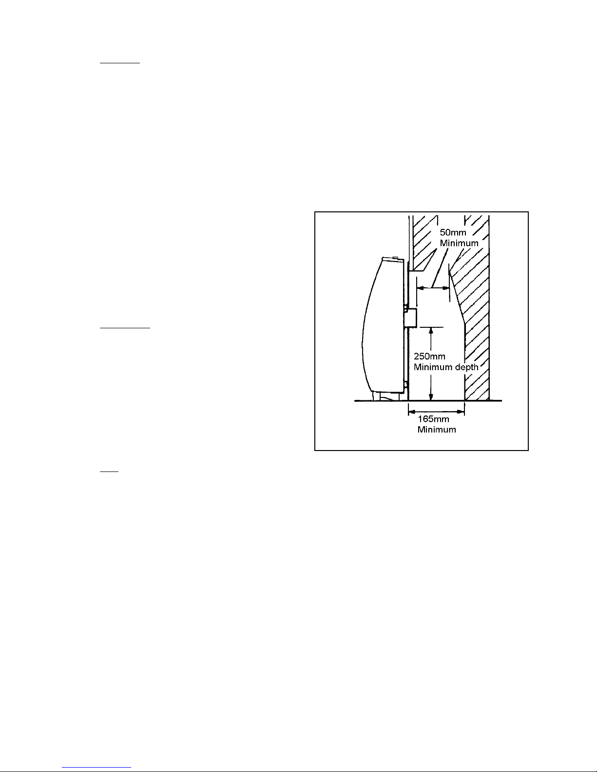
2.5. The flue spigot and any spigot extension must be
capable of passing through the closure plate by at
least 25mm with a minimum clearance of 50mm
between its open end and the nearest obstruction.
There must be a minimum clearance of 165mm
between the back of the closure plate and the back of
the catchment space.
The catchment space below the flue spigot must
extend at least 250mm downwards measured from
the bottom of the f lue spigot. See figure 2.
2.6. The front face of the fireplace should be reasonably
flat to ensure that a good seal can be made with the
closure plate.
2.7. The minimum clearance from the top surface of the
appliance to the underside of any shelf made from
wood or other combu s ti bl e materials is as follows:-
• For a shelf up to 150mm deep
Minimum height = 203mm
• For a shelf deeper than 150mm
203mm + 12.5mm f or every 25mm depth over
150mm.
2.8. The minimum allowab le dist a n ce t o a cor ne r wall o r
other projection at either side which extends further
forward than th e front of the appliance i s 100mm.
2.9 The space between the back of the outer case and the
front face of the f irepla ce must no t be filled in. Note:
The Valor d ecorative cover plate is suitable for use.
2.10. Note that soft wall coverings (e.g. embossed vinyl,
etc.) are easily affected by heat. They may scorch or
become discoloured when close to a heating
appliance. Please bear this in mind when installing.
2.11. An extractor fan may only be used in the same room
as this appliance, or in any area from which
ventilatio n fo r t he appliance is take n, if it does not
Figure 2
 Loading...