

Page 1
CONTOUR
MODEL 3290 - TEAK FINISH
&
SILHOUETTE
MODEL 3291 - MAHOGANY FINISH
MODEL 3297 - BLACK ASH FINISH
RADIANT / CONVECTOR GA S FIRES
INSTALLATION & SERVICING INSTRUCTIONS
THIS APPLIANCE IS FOR USE WI TH NATURAL GAS (G20) AT A
SUPPLY PRESSURE OF 20mbar (8in w. g.)
THIS APPLIANCE IS FOR US E IN THE UNITED KINGDOM (GB)
AND THE REPUBLIC OF IRELAND (IE) ONLY
INSTALLER: Please leave these instruc tions with the owner
600A591/04
Page 2
2
LIST OF CONTENTS
Page
Appliance dimensions 2
Appliance data 3
General installation requirem ents 3
Unpacking & pre-installation preparat io n 5
• Carton contents
5
• Fireplace flue pull check
5
• Preparing applianc e for installation
5
• Closure plate fitting
6
Appliance installation 7
• Hearth in s tallation
7
• Wall mount in g
7
• Gas supply connection
7
• Radiants fitting
7
Operating checks 7
• Control settings check
7
• Spillage check
7
• Final assem b ly
8
Final review 8
Servicing & p art s replacement 9
• Radiants re placement
9
• Outer case removal
9
• Pilot unit re p lac e ment
9
• Burner, gas tap & pilot removal
9
• Gas tap or injector replacement
9
• Piezo ge n erator replacement
9
• Gas tap greasing
10
• Complete fire removal
10
Short list of spares 10
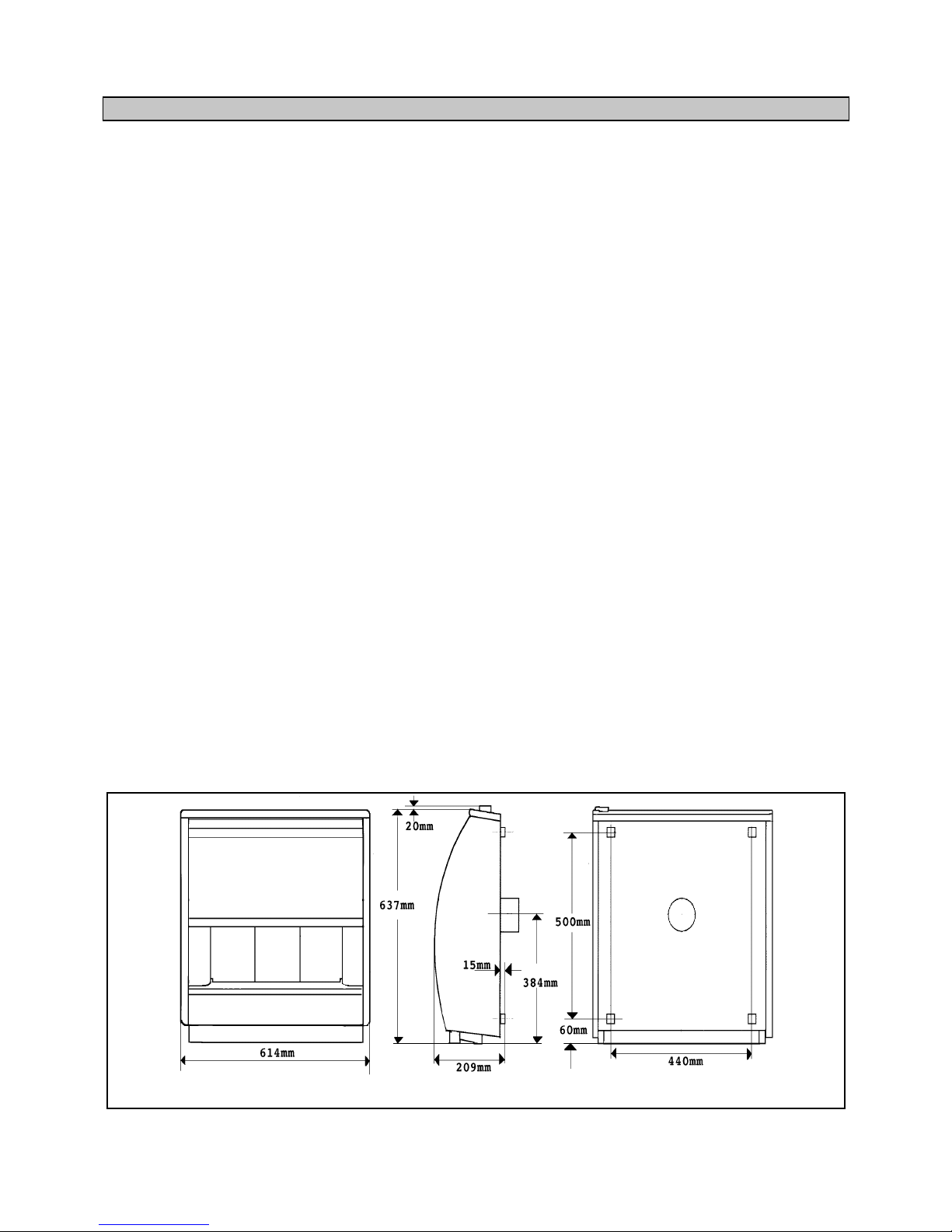
Figure 1 Appliance dimensions
Page 3

3
1. APPLIANCE DATA
This appliance does cont a in no t a ny co mpo ne nt ma nufa ct ur ed
from asbestos or asbestos r elated products.
The appliance dat a label is on the inner fa ce of the me tal cas e
at the left side. It is visible when the outer case is removed.
Gas: Natural (G20)
Inlet pressure: 20mbar (8in. w.g. )
Input - Max: 5.28kW (18,000Btu/h)
(Gross) Min 1.25kW (4,300Btu /h)
Output - Max 3.2kW (10,900Btu /h )
Min 0.56kW (1,900Btu/h)
Burner injectors:
Upper (Centre radiant) Bray cat 28 size 120
Lower (Outer radi an ts ) Bray cat 28 size 250B
Burner test pressure (cold): 18.3mbar (7.2in w.g.)
Inlet pipe connection: Rp1/4 (1/4” BSP)
Pilot & Atmospher e s e n s i n g d e vi ce SIT ref. O P9044
Ignition: Piezo electric
Integral w ith gas tap
Aeration: Non-adjustable.
2 GENERAL INSTALLATION REQUIREMENTS
2.1 The installation must be in accordance with these
instructions. For the user’s protection, in the United
Kingdom, it is the law that all gas appliances are
installed by competent persons in accordance with
the current edition of the Gas Safety (Installation &
Use) Regulations. Failure to install the appliance
correctly could lead to prosecution.
The Council for the Registration of Gas Installers
(CORGI) requires its members to work to
recognised standards.
In the United Kingdo m, the installa tion must be in
accordance with:
a) All the relevant parts of local regulations.
b) The Building Regulations issued by the
Department of the Environment and the Welsh
Office or the Building Standards (Scotland)
(Consolidation) Regulations issued by the
Scottish De v elopment Department.
c) All relevant codes of practice.
d) The relevant parts of the current editions of the
following British Standards:-
BS 715
BS 1251
BS 1289 Part 1
BS 1289 Part 2
BS 4543 Part 2
BS 5440 Part 1
BS 5440 Part 2
BS 5871 Part 1
BS 6461 Part 1
BS 6891
In the Republic of Ireland the installation must
conform to
a) The current editions of :-
ICP3
IS 813
b) All relevant national and local regulations in
force.
2.2 The appliance must not stand on a carpet or any
other combustible material.
If a panel has to be fitted to the fireplace opening to
meet the required opening sizes shown below, it
must be made of non-combustible material.
2.3 The appliance can be installed in the following
situations:
2.3.1 Convention al f ireplace and hearth
The appliance can be installed to a fireplace complete
with surr o u nd and hearth.
The fireplace opening must be within the following
dimensions:
Width: Max. 457mm
Min: 305mm
Height Max: 610mm*
Min. 510mm
* Though the total height of the closure plate will
accommodate a maximum opening height of
650mm, heights abov e 61 0mm will lea ve t he clos ure
plate and sealing tape visible above the appliance.
The appliance must be mounted on a noncombustible hearth (N.B. conglomerate marble
hearths are considered as non-combustible). The
hearth must be at lea st 8 80mm w ide x 3 00mm de ep.
The hearth material must be at least 12mm thick.
The periphery of the hea rth (or fender) should be at
least 50mm above floor level to discourage the
placing of carpets or ru gs over it.
The appliance can be fitted to a purpose made
proprietary class “O ” 100“C or 150°C su rr ou n d .
2.3.2. Wall mounted
The appliance can be wall mounted.
The appliance is not suitable for installation on
combustible walls.
The opening must be within the following
dimensions:
Width: Max. 356mm
Min. 305mm
Height: Max. 610mm*
Min. 376mm
* Though the total height of the closure plate will
accommodate a maximum opening height of
650mm, heights abov e 61 0mm will lea ve t he clos ure
plate and sealing tape visible above the appliance.
The bottom of the side feet must be at least 102mm
above the finished floor covering. This requires that
the top of the opening must be at least 612mm above
the finished floor covering.
Page 4
4
2.3.3.
Precast fl u e
The appliance can be insta lled to a f ireplace t hat has
a precast concrete or clay flue block system
conforming to BS1289. The appliance is suitable for
installations conforming to older versions of BS1289
as well as the curr ent edition. The flue blocks must
have a minimum widt h not less than 63 mm and a
cross-sectional area not less than 13,000mm
2
.
Older
editions of BS1289 required a cross-sectional area of
13,000mm
2
. The current revision of the standard
requires 16,500mm
2
. This appliance is suitable in
both cases.
The chimney should be one or two storeys high but
not less than 3m vertical height and be correctly
terminated. No mortar fangs between the blocks
should be extruded into the flueway. If raking blocks
are used, they must be fitted in accordance with the
manufacturer’s instructions. Mortar must not be
allowed to drop dow n and accumulate in the raked
positions.
The fireplace opening must be within the following
dimensions:
Width: Max. 457mm
Min: 305mm
Height Max: 610mm*
Min. 610mm*
2.3.4. Metal flue box
The appliance can be installed to a metal flue box
complying with the constructional requirements of
the current edi ti on of BS715.
The opening must be within the following
dimensions:
Width: Max. 457mm
Min: 380mm
Height Max: 610mm*
Min. 510mm
*Though the total height of the closure plate will
accommodate a maximum opening height of
650mm, heights abov e 61 0mm will lea ve t he clos ure
plate and sealing tape visible above the appliance.
2.3. Flues
Suitable flues are:
a) 225mm x 225mm conventional brick flue. If a
liner is used, it must be a minimum of 127mm
(5in.) diameter. The liner must be sealed to the
surrounding area above the fireplace opening and
to the top of the chimney and have an approved
terminal.
b) A prop erly constructed precast flue conforming
to BS1289 (See section.2.3.3.)
c) A flue pipe with a minimum diameter of 127mm
(5in.) . See BS6461 Part 1 for suitable materi al s .
Metal flue pipes must comply with BS715. See
section 2.3. 4. for metal flue box requir em en ts .
2.3.1. The flue must have a minimum equiva lent h eight o f
3m.
2.3.2. The flue must serve only one fireplac e.
2.3.3. Any damper or register plate should be removed. If
removal is not possible without carrying out
structural work, the damper or plate may be left in
the flue provided that it is permanently secured in the fully
open position.
2.3.4. If the appliance is intended to be installed to a
chimney which was previously used for solid fuel,
the flue must be swept clean prior to installation. All
flues should be inspecte d for so undness and freedo m
from blockages.
2.4 If the fireplace opening is an underfloor draught
type, it must be sealed to stop any draughts.
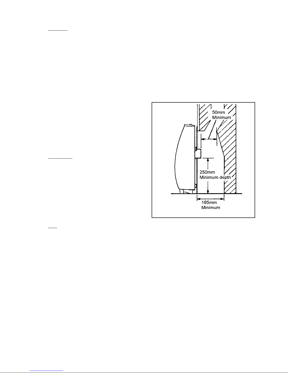
2.5. The flue spigot and any spigot extension must be
capable of passing through the closure plate by at
least 25mm with a minimum clearance of 50mm
between its open end and the nearest obstruction.
There must be a minimum clearance of 165mm
between the back of the closure plate and the back of
the catchment space.
The catchment space below the flue spigot must
extend at least 250mm downwards measured from
the bottom of the f lue spigot. See figure 2.
2.6. The front face of the fireplace should be reasonably
flat to ensure that a good seal can be made with the
closure plate.
2.7. The minimum clearance from the top surface of the
appliance to the underside of any shelf made from
wood or other combu s ti bl e materials is as follows:-
• For a shelf up to 150mm deep
Minimum height = 203mm
• For a shelf deeper than 150mm
203mm + 12.5mm f or every 25mm depth over
150mm.
2.8. The minimum allowab le dist a n ce t o a cor ne r wall o r
other projection at either side which extends further
forward than th e front of the appliance i s 100mm.
2.9 The space between the back of the outer case and the
front face of the f irepla ce must no t be filled in. Note:
The Valor d ecorative cover plate is suitable for use.
2.10. Note that soft wall coverings (e.g. embossed vinyl,
etc.) are easily affected by heat. They may scorch or
become discoloured when close to a heating
appliance. Please bear this in mind when installing.
2.11. An extractor fan may only be used in the same room
as this appliance, or in any area from which
ventilatio n fo r t he appliance is take n, if it does not
Figure 2
Page 5
5
affect the safe performance of the appliance. Note
the spillage test requireme nts detailed further on in
this manual. If the fan is likely to affect the appliance,
the appliance must not be inst alled unless the fa n is
permanently disconnec ted.
2.12. In the United Kingd om N o specia l v ent ilation bricks
or vents are required in the room for this appliance.
In the Republic of Ireland permanent ventilation
must comply with the regulations currently in force.
3. UNPACKING & PRE-INSTALLATION PREPARATION
3.1 CARTON CONTENTS
The carton contains:
1 Fire assembly
3 Radiants (In pack in radiant box)
1Closure plate
1 Flue spigot
1 Spigot restrictor
4 Screws for flue spigot
1 Bottom trim
2 Knurl e d s crews for bottom trim
1 Set of installation & users instructions
Carefully remove the contents. Check that all the
listed parts are present and in satisfactory condition.
3.2. FIRE PL ACE FLUE PULL
After preparing the fireplace, apply a lighted match,
paper or smoke match to the chimney opening.
Observe the smoke. If there is a definite flow into
the opening continue with the installation. If there is
not a definite flow, preheat the chimney for a few
minutes and recheck If there is still no definit e flow,
the chimney may need attention. Do not fit the
appliance. Seek expert advice.
3.3. A PPL IANCE PREPARATION
3.3.1
Stand the fire upright.
3.3.2 Remove the control knob by pulling clear of the ga s
tap spindl e .
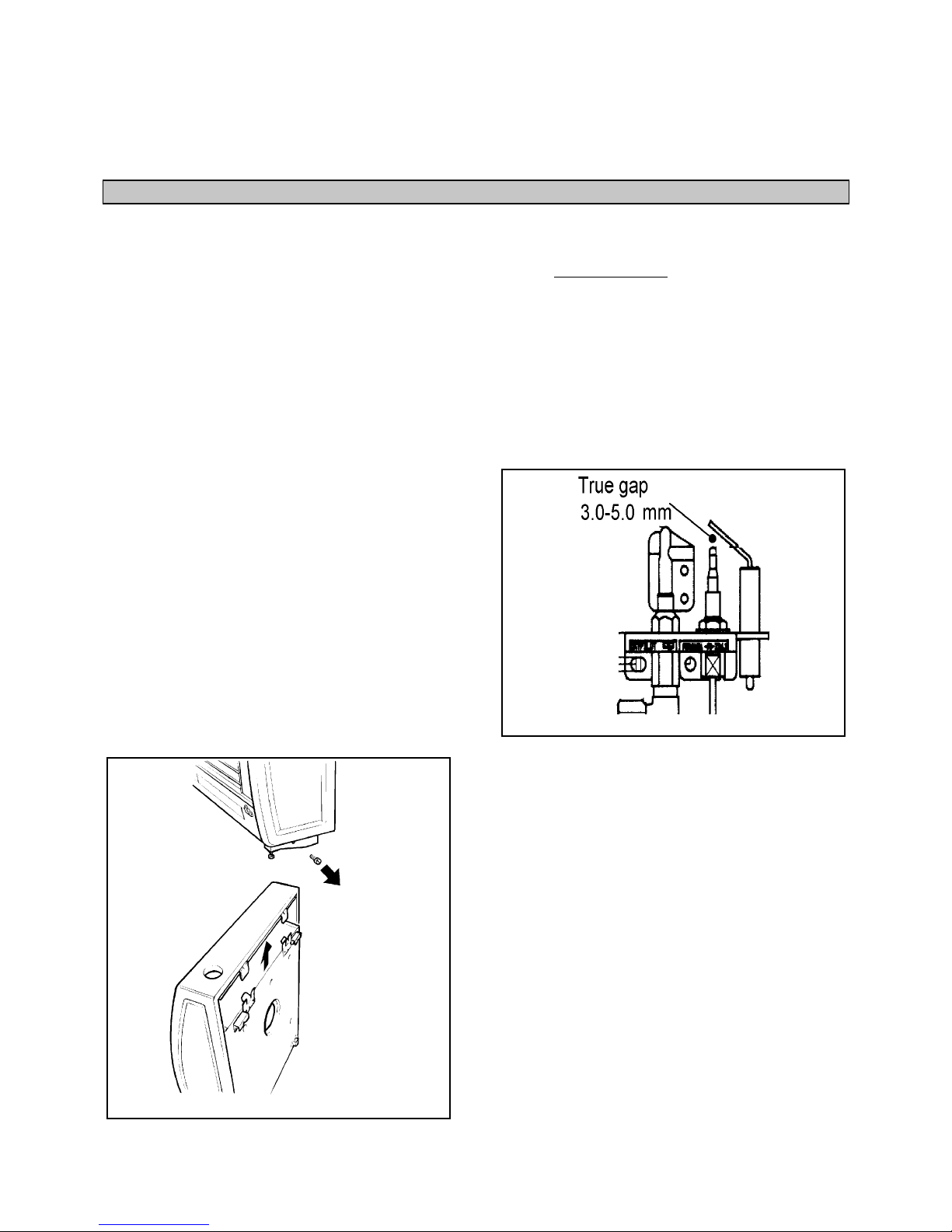
3.3.3 Remove the outer case retaining screws at the
bottom sides of th e f ire (Figure 3).
3.3.4 Lift the outer case up and forward to clear the top
retaining brackets and the gas tap spindle (Figure 3).
Put the case in a safe place.
3.3.5 Remove th e r ad iant pack.
3.3.6. Remove any protective film from all the bright trims.
3.3.7. Chec k ignition spark
Before att e mp t ing t o inst a ll, it is worth checking that
the piezo electric spark ignition system operates
satisfactorily.
To initiate the spark, refit and depress the control
knob. While keeping it depr essed, t urn to the 1 /IG N
position. A spark should track from the electrode pin
to the thermocouple tip. If there is no spark or
incorrect tracking, check the spark gap between the
electrode wire and thermocouple tip (see figure 4). If
the spark gap is correct, check the ignition wiring.
Remove the control knob after checking.
3. 3.8 Fit the flue spigot to the back of the fire using four
screws prov ided. The fire is supplied with a spig ot
restrictor which is intended for use where the flue
draught is excessive. The restrictor must not be
fitted to a flue with an effective height less than
4m or where a precast flue is used. Where the
restricto r is requir ed, fit it a t t his st age, b etwee n the
flue spigot and the back of the fire. There may,
however, b e ce rt ain except io na l circums t a nce s w her e
fitting the restr ictor cause s the fire t o fail t he sp illage
test (see section 5.2). In such cases the restrictor will
have to be removed.
3.3.9 I f th e f ire is fitted to a rece s s ed fireplace, an exte nsion
flue spigot up to a maximum total length of 125mm
may be used. The extension must be a tight fit over
the flue spigot and be secured by two self tapping
screws. Note the minimum clearance required as
shown in figure 2.
Figure 3 Outer case removal
Figure 4. Pilot spark gap
Page 6

6
3.4. FITTING THE CLOSURE PLATE
(Figures 5,6 & 7)
3.4.1.
If a centre gas pipe connection is required cut an
opening at the bottom of the closure plate. (The gap
between the pipe and the opening in the closure
plate should be sealed with tape after connection,)
3.4.2. Hearth mounting (figure 6)
The closure plate must be fitted and sealed to the
hearth and fireplace opening using a suitable heat
resistant material. If necessary cut the closure plate.
Leave the closure plate sufficiently large to overlap
the fireplace opening by 25mm. Make sure that the
rectangular air relief openings are fully within the
fireplace opening.
3.4.3 Wall mounting (Figure 7)
The closure plate must be fitted and sealed to the
fireplace opening using a suitable heat resistant
material. If necessary cut the closure plate. Leave the
closure plate sufficiently l arge to overlap the fireplace
opening by 25mm. Make sure that the rectangular air
relief openings are fully within the fireplace opening.
The bottom of the side feet must be at least 102mm
above any carpet or other floor covering. To achieve
this, the bottom of the closure plate must also be at
least 102mm above the finished floor covering. The
centre of the flue spigot hole will be at least 486mm
above the finished floor covering.
1. To improve appearance, remove the front
adjustment screws from below the side feet.
2. Place the closure plate over the fireplace opening in
its proper position.
3. Mark the positions of the four wall fixing holes. Use
only the lower of the top two pairs of holes.
4. Remove the pla te. Drill and plug t he wall using no.
10 wall plugs.
5. Put th e c losure plate back in pos ition. Make sure that
the holes line up with the wall plug s. S eal the plate to
the wall with suitable heat resistant tape.
3.4.4. Check the flue pull with closure plate fitted by
applying a lighted match or smoke match to the flue
spigot opening in the closure plate and observe the
smoke. If there is a definite flow continue with the
installation. If not check the fitting of the closure
plate. The fireplace flue pull check described in
section 3.2 should have confirme d that the f ireplace
itself is satisfactory.
Figure 5. Cl os u re plate
Figure 6. Closure plate fixing to hearth
Figure 7. Closure plate fixing to wall opening
Page 7

7
4. APPLIANCE INSTALLATION
4.1. INSTALLING TO A HEARTH
4.1.1.
Place the fire centrally on the hearth making sure
that the spigot lines up with the spigot hole in the
closure plate. Gently slide the appliance into place.
The spigot must enter the closure plate to a depth of
at least 25mm (see figure 2).
4.1.2. Level the appliance on the hearth by slackening the
two locknuts and turning the le velling screws up or
down as required while they bear on the hearth.
When the fire is level and square to the wall,
retighten the locknuts.
4.2. WA L L MOUNTING
4.2.1.
Fit two no. 10 x 2in. long woodscrews in the top two
fixing holes. Do not screw fully home at this stage.
Leave about 12mm of sc r ew pr otru d ing.
4.2.2. Lift the fire and angle it backwards to engage the
support brackets on to the top fixing screws.
Carefully pivot the fire downwards to engage the
flue spigot in the closure pl ate.
4.2.3. Fit two screws through the bottom spacing brackets
and into the lower fixing holes . Fully tight en all fo ur
screws.
4.3. GA S SUPPL Y C ONNECTION
4.3.1.
An Rp1/4 (1/4in. B.S.P.) elbow connector is
provided. This can be revolved through 360° to the
connection position required. If a rear centre
connection is required thr oug h a n o p ening cut in t he
closure plate (see section 3.4.1.), seal the gap between
the plate and th e p i p e with tape after connec ti o n .
4.3.2. Provision for isolation of the gas supply must be
provided upstream of the appliance for safety and
servicing.
4.3.3. The supply pipe must be of a rigid material (e.g.
copper). A flexible connection must not be made.
4.3.4. Pressure check the installation pipework for gas
soundness in accordance with the current edition of
BS6891.
4.4. FITTING THE RA D IA N TS
Fit the radiants ensuring that they rest against the
rear support bar and that their bottom front edges
are behind the retaining tags near the front of the
radiant box.
5. FULL OPERATING CHECKS & FINAL ASSEMBLY
5.1. CHECK CONTROL SETTINGS
5.1.1
Temporarily refit the control knob. Depress the
knob and turn anticlockwise partially towards the
1/IGN position until some resistance is felt. Keep
depressed at this position for a few seconds t o purge
air from the system then, while keeping it depressed,
turn fully to the 1/IGN position. A spark should be
generated at the pilot while turning. The spark
should ignite the pilot.
5.1.2. When pilot ignition has been achieved, keep the
control knob depressed for approximately ten
seconds to allow the thermocouple probe to warm
up and then re lease it. If the p ilot does not remain
alight, ensure tha t the air has been purged, that the
pilot orifice is clear and that the thermocouple
connections are sound. Replace the pilot unit if
necessary (see servicing section of this manual).
5.1.3. Check all the c ontrol settin gs. These are: -
Knob
Position
2 Centre radian t on low. Outer
radiants off.
3 Centre radian t on f ull. Outer
radiants off.
4 Centre radian t on f ull. Outer
radiants on low.
5 All radiants on full.
5.1.4. Check referenc e pressure
The appliance is pre-set to give the correct heat input
at the inlet pressure shown in section 1 of this
manual. No adjustment is necessary. Check the
burner pressure by fit ting a pressure gauge at the test
point. The test point is on the gas tap. Check the
pressure with the appliance alight and set at
maximum output (Control position 5).
After checking, turn off the appliance. Remove the
pressure gauge and replace the test point sealing
screw. Relight t he applia nce. Turn to t he max imum
output position and test around the sealing screw for
gas soundness with a suitable leak detection fluid.
5.2. SPILLAGE CHECK
A spillage check must be made before leaving the
installed appliance with the customer.
5.2.1 Close all doors and windows in the room containing
the appliance.
5.2.2 Light the appliance and set the control knob to the
maximum position (Position 5).
5.2.3 Leave the appliance on for fi ve m i n u tes.
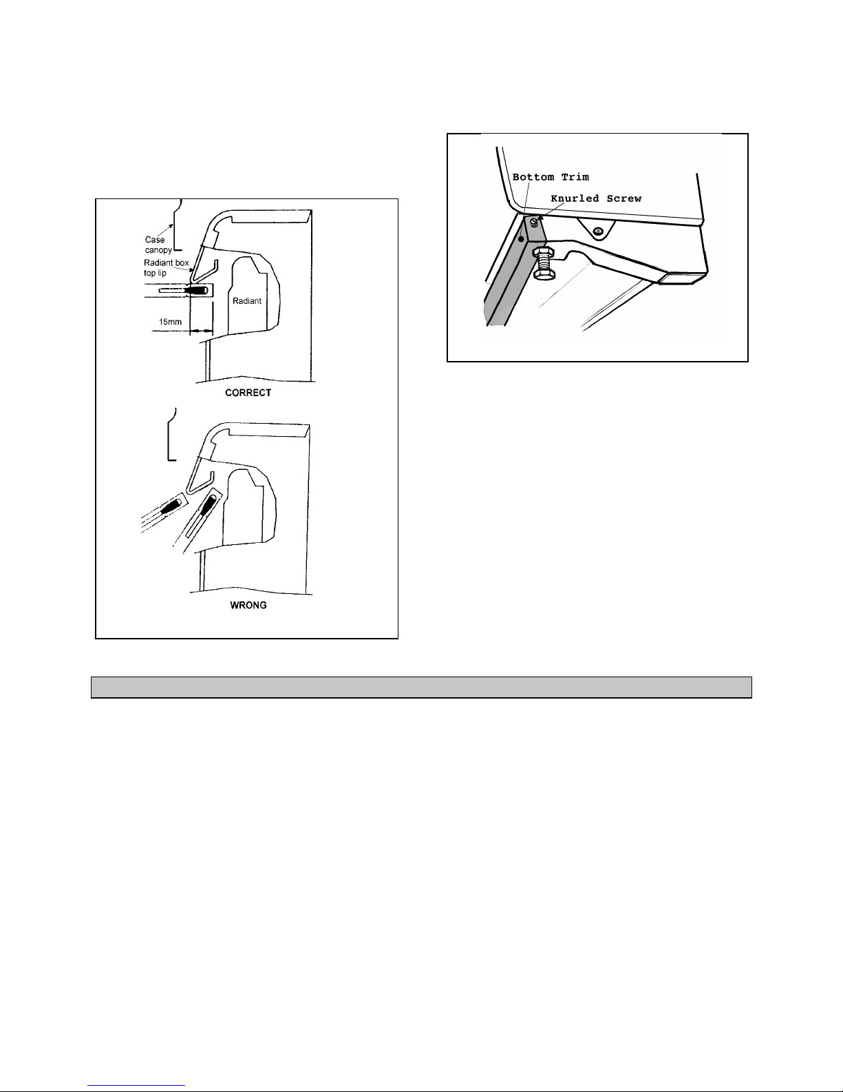
5.2.4 Place the smoke match tube horizontally under the
top lip of the radiant box and at least 50mm away
from the sides of the radiant box. See figure 8.
The installa tion is sat isfacto ry if the smo ke is drawn
into the appliance. If the smoke is not drawn into the
appliance, leav e the ap pliance alight at t he ma ximum
setting for a further ten minutes and then repeat the
test. If the smoke is still not drawn into the
appliance, inspect the sealing of t he closure plate. If
the sealing is satisfactory but the appliance is installed
with the flue restrictor (see section 3.3.8), remove
the restrictor, reseal the appliance and retest. If
smoke is still not drawn into the appliance
Disconnect the appliance and seek expert advice.
5.2.5 If the above test is satisfactory, open all internal
connecting doors, hatches, etc. in the room. Keep all
doors and windows that open to the outside of the
building closed. reche ck for spillage as abo ve. If an
Page 8
8
extractor fan is installed in the same room as the
appliance or a connecting room, check that spilla ge
does not occur with the fan operating and all doors
and other openings between the fan and the
appliance open. If the smoke is drawn into the
appliance, co nt inue w it h t h e ins t a lla t io n. If t he t e st is
not satisfactory, Disconnect the appliance and advise
the customer of the cause of failure
5.3 FINAL ASSEMBLY
5.3.1
Fit the bottom trim using the two knurled screws to
secure it to the side feet (see figure 9)
5.3.2 Remove the c ontrol knob.
5.3.3 Refit the outer case making sure that the metal
flanges at the top of the wood case locate fully in the
brackets at the top of th e b ac k p an e l .
5.3.4 Refit the outer case retaining screws at the bottom
sides.
5.3.5 Re f it the control knob.
6. FINAL REVIEW
6.1. Rec hec k the operation of the c ontrol.
6.2. Visually inspect the a ppliance. Clea n off any marks
incurred during installation.
6.3. Advi se the c ustom er how to operate the appliance.
6.4. Advise t he user that the appliance can be lit with a
match if necessa ry b y ins er t ing it t hro ug h t h e central
opening at th e b ottom of the radiant box.
6.5. Advise that the dressguard can be removed to replace
the radiants. Show the customer how to remove the
guard.
6.6. Advise that any cleaning must only be carried out
when the fire is off and cold.
6.7. Mention that the radiants may become brown with
use, that this is quite normal and has no adverse
effect.
6.8. Recommend that the appliance should be serviced
and the chimney inspected by a competent person at
least annually.
6.9. Hand these in structions and the user' s instructions to
the customer.
Figure 8. Smoke match tube positi on
Figure 9 B ottom trim
Page 9

9
7. SERVICING & PA RT S RE PL A C E ME NT
• Always turn off the gas supply and make sure that the
appliance is cool b e f o re c o mme ncing any servicing.
• Alway s t est fo r ga s so un dness and spil l a ge after ser vicing the
appliance.
• It is recommended that, at least once a year, the appliance is
disconnected and the catchment space behind the closure plate
checked and cleared of any debris. The closure plate must be
resealed to the wall after c h ecking.
7.1. TO RE PL ACE RADIANT(S)
7.1.1. Remove the dress guard by pressing down the two
hooks at the top. T i lt the guard forward and lift out.
7.1.2. Remove the old radiant(s) Fit the new radiant(s)
ensuring that they rest against the rear support bar
and that their bottom front edges are behind the
retainin g tags near the front of the radi an t b ox.
7.1.3. Replace the dress gu ard.
Locate the bottom of the dress guard in the two
holes in the bottom panel apron. Engage the two
spring projections at the top of the guard in the slots
under the f r on t decorative canopy.
7.2 TO REMOVE THE OUTER CASE
7.2.1
Remove the contro l knob by pulling clea r of the g as
tap spindl e .
7.2.2 Remove the outer case retaining screws at the
bottom sides of th e f ire (Figure 3).
7.2.3 Lift the outer case up and forward to clear the top
retaining brackets and the gas tap spindle (Figure 3).
Put the case in a safe place.
7.3. TO REPLACE THE PILOT UNIT
7.3.1.
Remove the outer case - see section 7.2.
7.3.2. Disconnect the thermocouple connection at the
bottom of the gas tap.
7.3.3. Disconnect the pilot pipe from the gas tap. It is the
upper con n e ction at the right sid e of th e tap.
7.3.4. Remove the first screw securing the dust cage to the
pilot unit & burner. Car efully remove t he dust cage
and place aside. Remove the second screw securing
the pilot u n it to the burner.
7.3.5. Disconnect the electrode lead from below the pilot
electrode. Carefully remove the dust cage.
7.3.6. Carefully remove the pilot unit together with the
pilot pipe then disconnect the pipe from the pilot
unit.
7.3.7. Replace in the reverse order.
Note: 1 The pilot unit must be replaced as a whole assembly.
Its individual components are not separately
replaceable.
2. Once removed, ensure that the dust cage is cleaned
before refitting. Make sure that it locates squarely
onto the pilot unit without any gaps between the
cage edges and the pilot unit.
.
7.4. TO REMOVE THE BURNER, GAS
TAP & PILOT ASSEMBLY
7.4.1.
Remove the outer case - see section 7.2.
7.4.2. Make sure that the gas tap is in the off position.
Disconnect the control spindle & adapter from the
gas tap by removing the split pin. Lift the adapter
clear of the gas tap spindle.
7.4.3. Disconnect the inlet pipe from the gas tap. It is the
lower con nection at the right side of the tap.
7.4.4. Slacken t he wing nut at the left side of the burner.
Remove the screw from the captive nut at the right
side of the burner. Carefully remove the burner, tap
& pilot unit.
7.4.5. Replace in the reverse order. Leave the burner fixing
screw and wing nut loose while reconnecting the
inlet pipe to aid alignment.
Make sure that the control knob with spindle is correctly
turned to agre e with the gas tap p osition bef ore refitti ng the
split pin.
7.5 TO REPLACE GAS TAP OR
INJECTOR(S)
7.5.1.
Remove the bu r n e r , tap & pilot unit - see section 7.4.
7.5.2. Disconnect the electrode lead from below the pilot
electrode.
7.5.3. Disconnect the thermocouple connection at the
bottom of the gas tap.
7.5.4. Dis c onnect the pilot pipe fr om the gas tap.
7.5.5. Remove the gas tap fixing nut from the burner and
slide ou t th e gas tap .
7.5.6. Unscrew the injector(s).
7.5.7. Replace in the reverse order using jointing
compound complying with BS 5292. Take care when
replaci n g the i nj e ctor s. The i n je ctor s h a ve cer a mi c ti p s a t each
end. It is importa nt n ot to a ll ow joi n tin g comp ou n d to get on
either end of the injectors.
Make sure that the control knob with spindle is correctly
turned to agre e with the gas tap p osition bef ore refitti ng the
split pin.
7.6 TO REPLACE THE PIEZO
GENERATOR
7.6.1.
Remove burn e r, tap & pilot unit - see sec ti on 7.4.
7.6.2. Disconnect the electrode lead from below the piezo
unit.
7.6.3. Straighten the tabs securing the piezo unit to the tap
niting plate and pull the pi ezo u n i t c l ear.
7.6.4. Replace in the reverse order. Twist the tabs on the
piezo unit to secure to the niting plate. Ma ke sur e that
the control knob with spindle is cor r ectl y tur n ed to a gr ee wi th
the gas tap position before refitting the split pin.
Page 10
10
7.7. TO GREASE TH E GA S TAP
7.7.1.
Remove the gas tap complete with piezo generator see section 7.5.
7.7.2. Remove the two screws and shakeproof washers
securing the piezo generator. Carefully lift the piezo
generator clear together with the gas tap h e ad .
7.7.3. Remove the spind l e and spri n g from the tap.
7.7.4. Note the position of the slot in the plug. Mark its
position on the tap body.
7.7.5. Rotate th e plug and pull it out of the tap.
7.7.6. Clean and grease the plug lightly with a suitable
grease. Do not apply excessive grease. Particularly,
make sure that the gas ports are not restricted by
grease.
7.7.7. Push the plug back into the tap body. Line up the
slot in the plug with the mark previously made on
the tap body.
7.7.8 Reassemble in the reverse order making sure that the
components are correctly engaged. Check the
operation of the tap and piezo. Make sure that the
control knob with sp i nd le i s cor r ectl y tur n ed to agr e e w i th the
gas tap position before refitting the split pin.
7.8. TO R EMOVE THE COMPLETE F IR E
TO CHECK CHIMNEY FOR
DEBRIS.
7.8.1.
Remove the outer case - see section 7.2.
7.8.2. Rem o ve th e radiants and store in a saf e place.
7.8.3. Undo the inlet connection at the elbow located
centrally below the burner.
7.8.4. If wall mounted, remove t he two lower fixing screws
located in the back panel below the burner then
remove the two upper screws accessible through the
upper canopy grill. Lift the fire away from the wall.
7.8.5. If hearth mounted, pull the fire away from the wall.
Take care that the levelling screw heads d o not scratch the
hearth surface.
7.8.6. Remove the cl osu re pl ate from the c h i m n ey open i n g.
7.8.7. Inspect the opening and clear away any debris from
the base of the f lue.
7.8.8. Reseal the closure plate and refit the fire in the
reverse order.
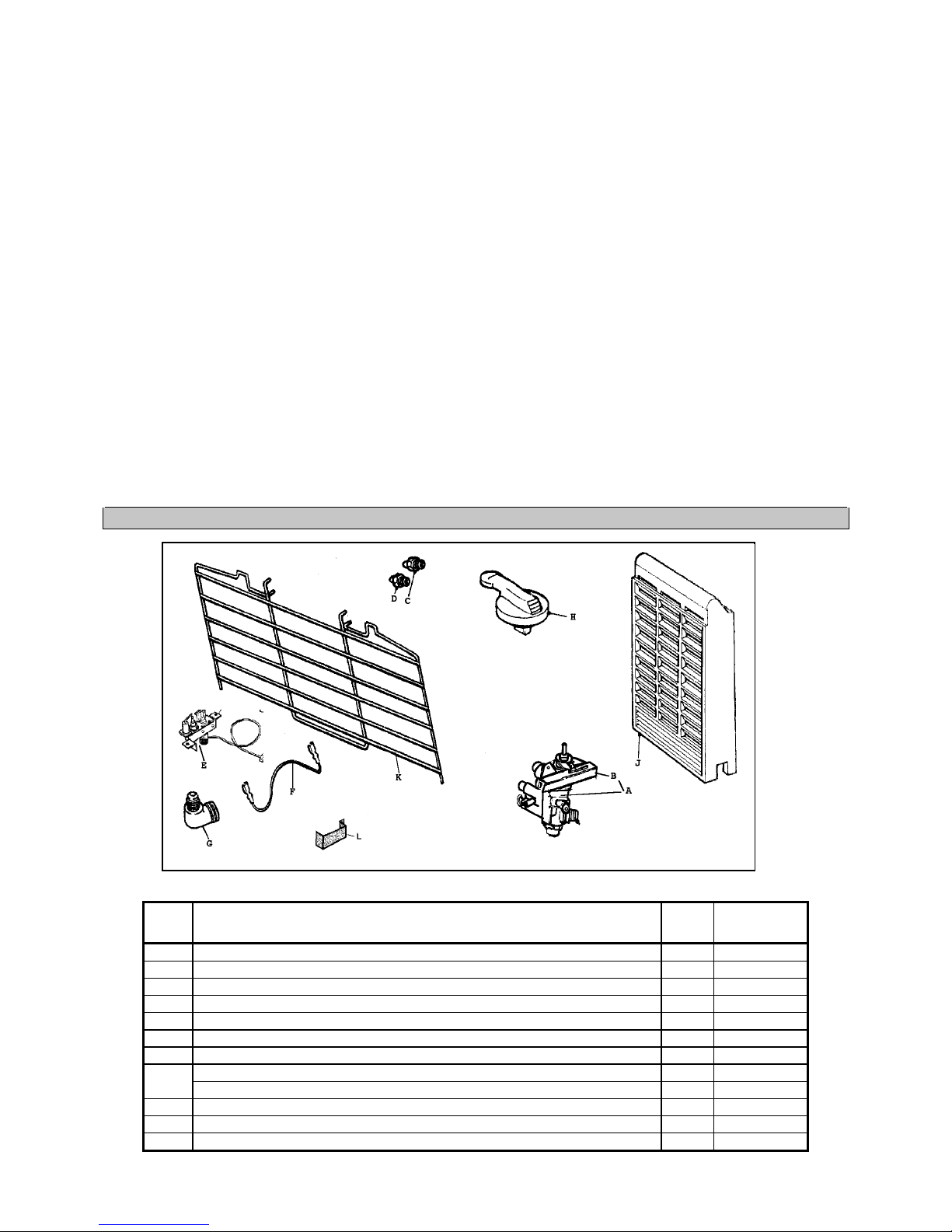
SHORT LIST O F SPARES
KEY DESCRIPTION No.
OFF
MAKER’S
PART No.
AGas tap 1 544609
B Piezo generator 1 536939
C Injector U pper B r ay c at 28 s i ze 120 1 544619
D In jector lower Bray cat 28 size 250B 1 545199
E Pilot unit 1 545949
F Electrode lead 1 544629
G Inl et elbow 1 532519
H Control knob (Con tour & Silhouette mahogany fin ish) 1 559759
Control knob (Silhouette Black ash fi n ish) 1 544659
JRadiant 3 544649
K Dress guard 1 559749
LDust cage 1 567619
Page 11

11
VALOR HEATING
ERDINGTON, BIRMINGHAM B24 9 QP
Because our policy is one of constant development and improvement, details may vary slightly from those given in this publication.
©Valor Heating
 Loading...