

Valor 2200JN, 2200JP Installation & Owner's Manual
LX2 Series
DV ZC Gas Fireplace
2200JN (natural gas) & 2200JP (propane gas)
Installation & Owner’s Manual
!
A barrier designed to reduce the risk of burns from the hot
viewing glass is provided with this appliance and shall be
installed for the protection of children and other at-risk
individuals.
! WARNING
FIRE OR EXPLOSION HAZARD
Failure to follow safety warnings exactly
could result in serious injury, death, or
property damage.
— Do not store or use gasoline or other
fl ammable vapors and liquids in the
vicinity of this or any other appliance.
— WHAT TO DO IF YOU SMELL GAS
▪ Do not try to light any appliance.
▪ Do not touch any electrical switch; do
not use any phone in your building.
▪ Leave the building immediately.
▪ Immediately call your gas supplier from
a neighbor’s phone. Follow the gas
supplier’s instructions.
▪ If you cannot reach your gas supplier,
call the fi re department.
— Installation and service must be perfor-
med by a qualifi ed installer, service
agency or the gas supplier.
DANGER
HOT GLASS WILL
CAUSE BURNS.
DO NOT TOUCH GLASS
UNTIL COOLED.
NEVER ALLOW CHILDREN
TO TOUCH GLASS.
Please read this manual BEFORE
installing and operating this appliance.
This appliance may be installed in an
after-market permanently located,
manufactured (mobile) home where not
prohibited by local codes.
This appliance is only for use with the type
of gas indicated on the rating plate. This
appliance is not convertible for use with
other gases, unless a certifi ed kit is used.
This appliance is a domestic room-heating
appliance. It must not be used for any other
purposes such as drying clothes, etc.
This appliance is suitable for installation in a
bedroom or bed sitting room.
Ce guide est disponible en français sur demande.
INSTALLER
Leave this manual
with the appliance.
CONSUMER
Retain this manual
for future reference.
4006158-01
©2017, Miles Industries Ltd.
Table of Contents
W
A
R
R
A
N
T
Y
P
R
O
G
R
A
M
V
A
L
O
R
C
O
M
F
O
R
T
V
A
L
O
R
C
O
M
F
O
R
T
FOR THE OWNER FOR THE QUALIFIED INSTALLER
Safety Precautions ................................................. 3
Safety and Your Fireplace ......................................4
Owner’s Information ............................................... 5
Operating Your Fireplace for the First Time ............... 6
Cleaning Your Fireplace ............................................6
Checking Pilot and Burner Flames ............................9
Replacing Batteries .................................................10
Using Remote Control Handset Wall Holder ........... 10
Replacing Light Bulbs .............................................. 10
Locating Lighting, Operation and Rating
Information Card ................................................... 11
Servicing Your Fireplace .......................................... 11
Fireplace Control Devices ....................................... 11
How to Turn Your Fireplace OFF (including pilot) .... 11
How to Ensure Your Fireplace Cannot
Be Turned ON Inadvertently .................................12
Remote Control Operation ................................... 13
Wall Switch Operation ..........................................19
Kits & Accessories ...............................................19
Lighting Instructions ............................................ 20
Warranty ................................................................69
R
O
M
L
A
R
A
G
Warranty Card at the
back of this manual.
W
O
V
R
P
Y
T
T
N
A
R
R
R
A
O
C
F
O
M
The information contained in this installation manual
is believed to be correct at the time of printing. Miles
Industries Ltd. reserves the right to change or modify
any information or specifi cations without notice.
Miles Industries Ltd. grants no warranty, implied or
stated, for the installation or maintenance of your
heater, and assumes no responsibility for any consequential damage(s).
Commonwealth of Massachusetts......................21
Specifi cations .......................................................23
Overview................................................................24
Dimensions & Location ........................................ 25
Clearances to Combustible Projections.............26
Framing Considerations ...................................... 27
Venting ...................................................................33
Installation Planning ............................................39
Plan Wall Finish .......................................................40
Installation ............................................................. 41
Unpack the Appliance ..............................................41
Remove the Barrier Screen and Window ................ 41
Install the Standoff s ................................................. 42
Install 6-5/8” x 4” Vent Adapter (if required) .............42
Install LDK HeatShift Duct Kit’s take-off collars to
appliance ..............................................................42
Prepare Appliance for Wiring ...................................42
Set-up Gas Supply ..................................................44
Initialize Remote Control .........................................45
Install Remote Battery and Wall Switch Kit RBWSK
(required) .............................................................. 46
Place the appliance in fi nal position ........................48
Complete Installation of LDK HeatShift Duct Kit ......48
Install Liners ............................................................49
Install Long Beach Driftwood Kit 1705DWK ............ 51
Install Decorative Glass Murano 2200DGM ............ 54
Install Decorative Glass Set 2200DGS ....................55
Install Splitwood Kit 1700SWK ................................ 56
Install Rocks & Shale Set 1714RSS ........................ 61
Check Operation ...................................................... 64
Set Aeration (if necessary) ...................................... 64
Shut-off Gas Supply ................................................64
Reinstall Barrier Screen ........................................... 65
Reinstall the protective carton ................................. 65
Install Remote Control Handset Wall Holder ...........65
Wiring Diagram .....................................................66
Approved Venting Components .......................... 67
Warranty ................................................................69
Spare Parts............................................................70
Designed and Manufactured by / for
Miles Industries Ltd.
190–2255 Dollarton Highway,
North Vancouver, BC, CANADA V7H 3B1
Tel. 604-984-3496 Fax 604-984-0246
www.valorfi replaces.com
2
Massachusetts: The piping and fi nal
gas connection must be performed by a
licensed plumber or gas fi tter in the State of
Massachusetts. Also, see Carbon Monoxide
Detector requirements on page 21.
© Copyright Miles Industries Ltd., 2017. All rights reserved.
Safety Precautions
!
READ and UNDERSTAND all instructions carefully
before starting the installation. FAILURE TO FOLLOW
these installation instructions may result in possible fi re
hazard and will void the warranty.
Prior to the fi rst fi ring of the fi replace, READ the
Owner’s Information section of this manual.
DO NOT USE this appliance if any part has been under
water. Immediately, CALL a qualifi ed service technician
to inspect the unit and to replace any part of the control
system and any gas control that has been under water.
THIS UNIT IS NOT FOR USE WITH SOLID FUEL.
Installation and repair should be PERFORMED by a
qualifi ed service person. The appliance and venting
system should be INSPECTED before initial use and at
least annually by a professional service person. More
frequent cleaning may be required due to excessive
lint from carpeting, bedding, etc. It is IMPERATIVE that
the unit’s control compartment, burner, and circulating
air passageways BE KEPT CLEAN to provide for
adequate combustion and ventilation air.
Always KEEP the appliance clear and free from
combustible materials, gasoline, and other fl ammable
vapors and liquids.
NEVER OBSTRUCT the fl ow of combustion and
ventilation air. Keep the front of the appliance CLEAR
of all obstacles and materials for servicing and proper
operation.
This unit MUST be used with a vent system as
described in this installation manual. NO OTHER vent
system or components MAY BE USED.
This gas fi replace and vent assembly MUST be vented
directly to the outside and MUST NEVER be attached
to a chimney serving a separate solid fuel burning
appliance. Each gas appliance MUST USE a separate
vent system. Common vent systems are PROHIBITED.
INSPECT the external vent cap on a regular basis to
make sure that no debris, plants, trees, shrubs are
interfering with the air fl ow.
TURN OFF the gas before servicing this appliance.
It is recommended that a qualifi ed service technician
perform an appliance check-up at the beginning of each
heating season.
DO NOT use this heater as a temporary source of heat
during construction.
State of California. Proposition 65 Warning. Fuels
used in gas, wood-burning or oil fi red appliances,
and the products of combustion of such fuels, contain
chemicals known to the State of California to cause
cancer, birth defects and other reproductive harm.
California Health & Safety Code Sec. 25249.6.
Due to the high temperature, the appliance should be
LOCATED out of traffi c areas and away from furniture
and draperies.
Clothing or fl ammable material SHOULD NOT BE
PLACED on or near the appliance.
This appliance is a DOMESTIC ROOM-HEATING AP-
PLIANCE. It must not be used for any other purposes
such as drying clothes, etc.
DO NOT place furniture or any other combustible
household objects within 36” of the fi replace front.
BE CAREFUL not to put any decorating objects
sensitive to heat to close above or around the fi replace
as it gets very hot when operating.
The glass door assembly MUST be in place and sealed
before the unit can be placed into safe operation.
DO NOT OPERATE this appliance with the glass door
removed, cracked, or broken. Replacement of the glass
door should be performed by a licensed or qualifi ed
service person. DO NOT strike or slam the glass door.
The glass door assembly SHALL ONLY be replaced
as a complete unit, as supplied by the fi replace
manufacturer. NO SUBSTITUTE material may be used.
DO NOT USE abrasive cleaners on the glass door
assembly. DO NOT ATTEMPT to clean the glass door
when it is hot.
A BARRIER DESIGNED TO REDUCE THE RISK OF
BURNS from the hot viewing glass is provided with
this appliance and SHALL BE INSTALLED for the
PROTECTION OF CHILDREN and other AT-RISK
INDIVIDUALS.
If the barrier becomes damaged, the barrier SHALL BE
REPLACED with the MANUFACTURER’S BARRIER
for this appliance.
Any safety screen, guard or barrier removed for servicing the appliance, MUST BE REPLACED prior to
operating the appliance.
Children and adults should be ALERTED to the hazards
of high surface temperature and should STAY AWAY to
avoid burns or clothing ignition.
YOUNG CHILDREN should be CAREFULLY
SUPERVISED when they are in the same room as the
appliance. Toddlers, young children and others may
be susceptible to ACCIDENTAL CONTACT BURNS.
A physical barrier is recommended if there are at-risk
individuals in the house. To restrict access to a fi replace
or stove, INSTALL AN ADJUSTABLE SAFETY GATE
to keep toddlers, young children and other at-risk
individuals out of the room and away from hot surfaces.
3
Safety and Your Fireplace
!
Safety and Your Fireplace
Please Read and Carefully Follow all Safety Warnings and
Operating Instructions Contained in Your Owner’s Manual
(Replacement Manuals are available by contacting our service department at
1-800-468-2567 or visit www.valorfi replaces.com).
Please Follow These Important
Child Safety Precautions and
Recommendations,
• Parts of your Valor Fireplace become
extremely hot while in operation.
• The glass viewing window
temperature can
exceed 500 F
at full capacity.
Momentary contact
with a hot glass
surface can cause
a severe burn, even if the fi replace
is operating at reduced heating
capacity.
withdraw in the event of accidental
contact with a hot surface.
• A physical barrier is strongly
recommended if there are young
children, or at-risk individuals in the
house. Install an approved aftermarket safety gate to keep toddlers,
young children and other at-risk
individuals a safe distance from the
fi replace.
• Keep the remote control handset
out of reach of children at all
times. A wall mount storage holster
is provided with your remote control
handset.
• The glass window will remain hot
for an extended period of time after
the fi replace has been turned off .
Ensure that children are prevented
from touching the fi replace during the
cool down period.
• Toddlers and Young Children
must be closely supervised at all
times when they are in the same
room as the operating fi replace. They
lack full awareness of danger and
rely on your protection. Toddlers,
in particular, do not have the motor
skills and response refl exes to
4
• Ensure that the fi replace, including
the pilot light, is completely turned
off when children are present and
close supervision and safety barriers
are not available—see pages 11–12
of Owner’s Information section.
• If the fi replace is not going to
be used for the summer or any
extended period of time, remove the
batteries from the remote control
handset and wall battery holder.
It is recommended that batteries are
replaced annually in any event—see
page 10.
Owner’s Information
• • Some materials or items, although safe, may
discolor, shrink, warp, crack, peel, and so on
because of the heat produced by the fi replace.
AVOID PLACING
candles, paintings, photos,
and other items
SENSITIVE TO HEAT
OWNER’S
INFORMATION
WARNING
!
EXTREMELY HOT!!!
• READ the SAFETY information on pages
3 and 4 of this manual BEFORE operating
your gas heater.
• Some parts of your fi replace are EXTREMELY
HOT, particularly the GLASS window.
• DO NOT LET CHILDREN touch the glass or
any parts of your fi replace even after it is
turned off as it is still hot.
• USE THE BARRIER SCREEN provided with
the fi replace to reduce the risk of severe
burns.
• Keep the remote control handset OUT OF
REACH of children.
• HOT WALL SURFACES! The wall directly above
the fi replace is VERY HOT when the fi replace
heats. It is constructed of non-combustible
materials and although safe, it may reach
temperatures in excess of 175º F depending
on choice of optional accessories.
Some materials or items, although safe, may
discolor, shrink, warp, crack, peel, and so on
because of the heat produced by the fi replace.
AVOID PLACING
and other items
36 inches (0.9 m) around the fi replace.
• Solid wood fl ooring in front of the fi replace (if
allowed) may shrink during the heating season
due to heat.
Performance of propane gas appliances may
be aff ected by the quality of commercial gas
supplied in your area.
candles, paintings, photos,
SENSITIVE TO HEAT within
Thank You ...
For purchasing a Valor by Miles Industries. Your new radiant
gas heater is a technical appliance that must be installed by
a qualifi ed dealer. Each Valor fi replace is fully tested during
the production process for your safety and comfort.
Your unit has been professionally installed by:
Dealer Name: ________________________________
Phone Number :_______________________________
Should you encounter an operational problem, call
your dealer immediately.
Do not try to repair the unit as you may cause an
injury or damage the fi replace.
This manual and particularly the preceeding and
following pages contain very important information
regarding the safe operation of your fi replace as
well as maintenance instructions.
Read carefully BEFORE operating your fi replace and
pay special attention to the SAFETY WARNINGS.
A heating gas appliance does require safe handling
and for this reason, we very strongly recommend that
no children be allowed to touch the fi replace and its
controls at all times. Do install a screen or barrier in
front of the fi replace to protect your children against
severe burns.
This appliance is designed and approved as a
supplemental heater and provides the potential
for most energy conservation when used while
attended. The use of an alternate primary heat
source is advisable.
WARNING
!
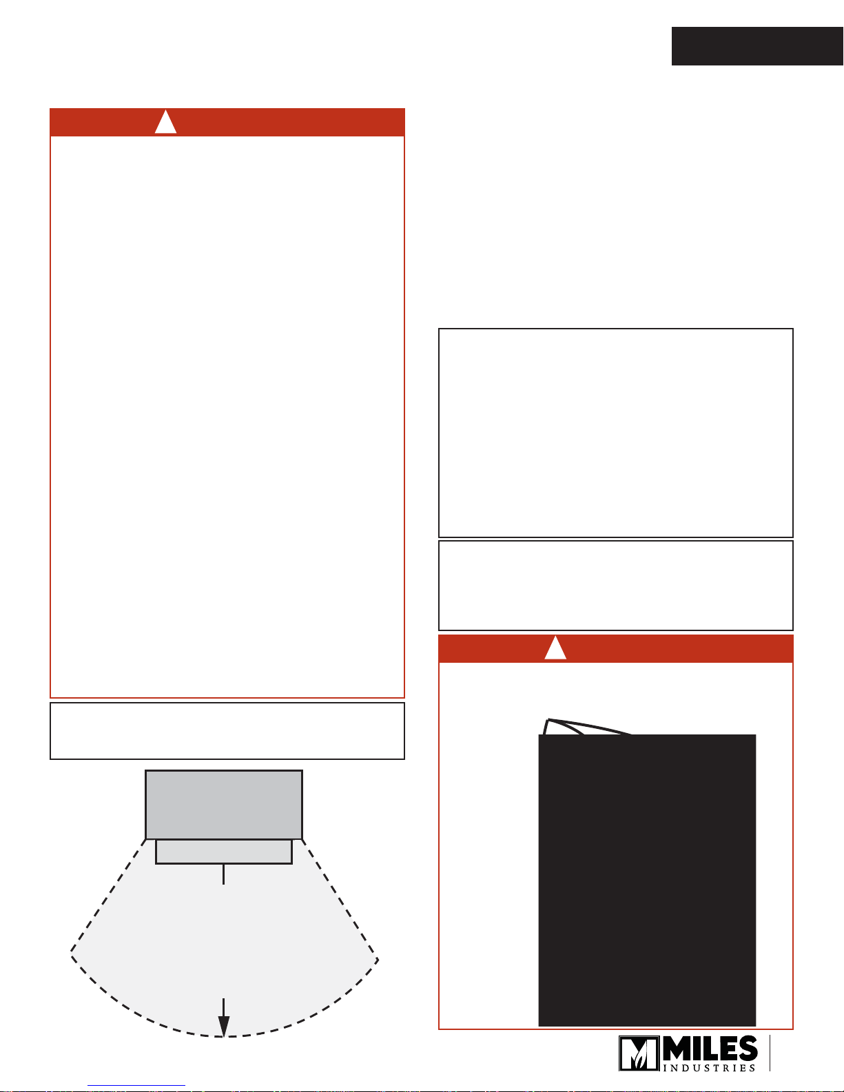
DO NOT COVER OR PLACE ITEMS IN
FRONT OF LDK HeatShift Duct Kit
OUTLET(S)!
Ceiling outlet
Fireplace
Hearth
Do not put
furniture or other objects
in this space in front of
the replace:
36” (0.9 m)
Front outlet
Sides
outlets
5

OWNER’S
INFORMATION
Owner’s Information
Operating Your Fireplace for the First Time
When operating your new fi replace for the fi rst time,
some vapors may be released due to the burning of
curing compounds used in the manufacture of the
appliance. They may cause a slight odor and could
cause the fl ames to be the full height of the fi rebox, or
even slightly higher, for the fi rst few hours of operation.
It is also possible that these vapors could set off any
smoke detection alarms in the immediate vicinity.
These vapors are quite normal on new appliances. We
recommend opening a window to vent the room. After
a few hours use, the vapors will have disappeared and
the fl ames will be at their normal height.
Flame Supervision Device
For your safety, this appliance is fi tted with a fl ame
supervision device which will shut-off the gas supply
if, for any reason, the pilot fl ame goes out. This device
incorporates a fi xed probe, which senses the heat
from the pilot fl ame. If the probe is cool, the device will
prevent any gas fl ow unless manually lighting the pilot.
See full lighting instructions on page 20 of this manual.
Cleaning Your Fireplace
Important - Glass cleaning - Mineral deposits
WARNING
!
DO NOT TOUCH THE GLASS WHILE IT IS HOT!
Let the fi replace cool fi rst before cleaning it.
of compromising the strength of the glass. An
emulsion type cleaner is recommended.
• Use a soft damp cloth to apply the cleaner. Dry the
glass with a soft, dry, preferably cotton cloth. Most
paper towels and synthetic materials are abrasive to
ceramic glass and should be avoided.
• Our dealers have had good results from the
products listed below. We cannot, however,
guarantee the results of these products.
◊ Brasso, Polish Plus by Kelkem, Cook Top Clean
Creme by Elco, White Off by Rutland, Turtle Wax
Do not clean the glass while it is hot!
Always securely replace the window and the barrier
screen before lighting.
If broken, the glass pane may only be replaced
as a complete window unit as supplied by the
manufacturer.
If the barrier becomes damaged, the barrier shall
be replaced with the manufacturer’s barrier for this
appliance.
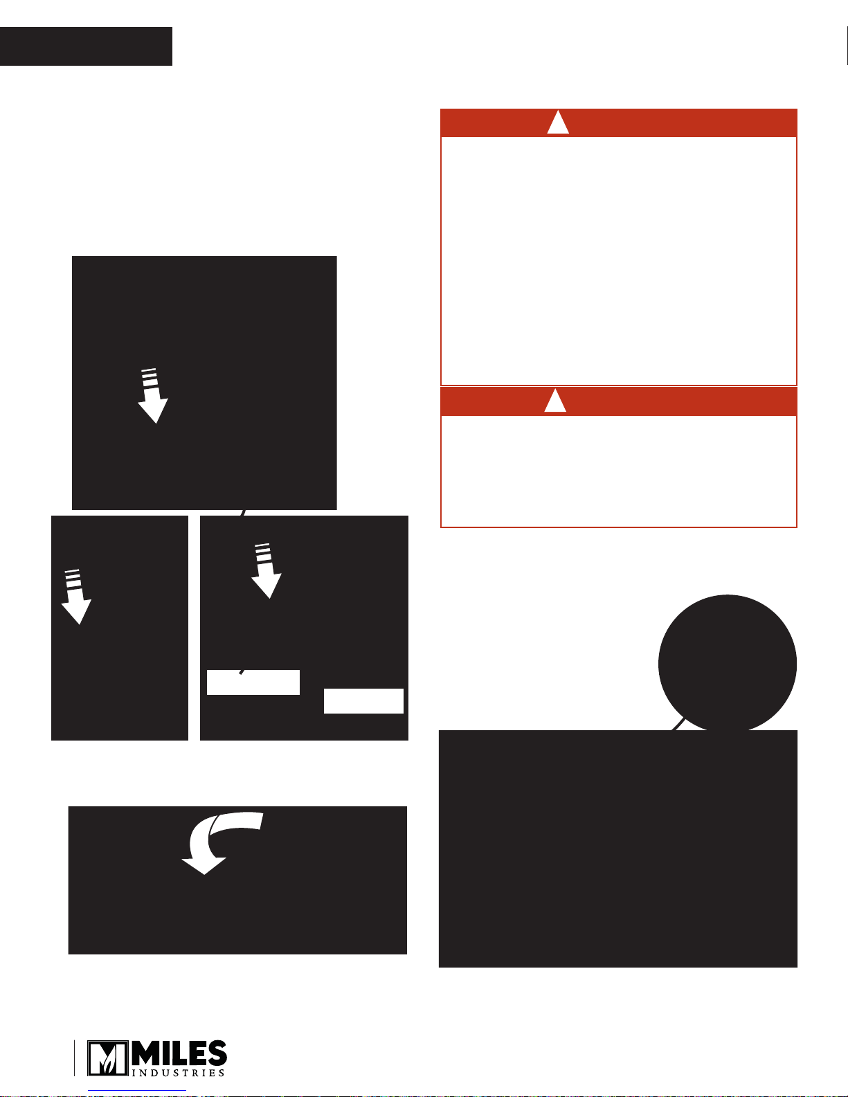
Only the front window pane needs to be removed
to access the interior of the fi replace. To remove
the window for cleaning:
1. Remove the 3-sided barrier screen carefully pulling
it straight out.
One of the by-products of the combustion process in
a gas appliance is a mineral which can show up as a
white fi lm on the ceramic glass of the viewing door.
The composition of the deposit varies with location and
time. It is believed to be associated with the varying
sulfur content of the gas. You may have the problem
intermittently.
We have consulted with ceramic glass manufacturers
and they cannot off er a defi nitive solution to this problem. Dealers have tried various cleaning products with
varying results. The following are recommendations
only and are not meant to guarantee results.
NOTE: This is a problem beyond Miles Industries’
control and is not covered under warranty.
• Clean the glass regularly as soon as you notice
the buildup (white fi lm). If the fi lm is left for a longer
period of time, it will etch into the glass. It is then
much harder, if not impossible, to remove.
• NEVER use an abrasive cleaner or ammoniabased cleaner on the ceramic glass. Any
abrasion of the surface has the immediate eff ect
2. Hook the window
handle to one of
the spring-loaded
window levers
6

Owner’s Information
3. Pull the lever up and unhook the window. Repeat
with the other lever.
4. Pull the top of the window
outward and lift it up behind
the front panel to disengage
it from its rail.
Note: If it is diffi cult, pull up
one side of the window fi rst,
then the whole window.
OWNER’S
INFORMATION
5. Once removed from
the bottom rail, rotate
the window pane
outward to take it out
completely; set it aside in a
safe place to avoid damage.
Clean the window panes following the guidelines in this
section.
Clean the steel trim with mild soap and warm water.
Any alcohol/solvent base cleaner will weaken the coating and damage it.
Clean the barrier screen dusting it with a soft brush.
Clean the fi rebox ceramic logs/rocks and walls dust-
ing them with a soft brush. Dust can also be removed
from the burner using a soft brush after removing the
fuel bed. When cleaning, make sure that no particles
are brushed into the slots of the burner.
WARNING
!
CHOKING HAZARD! Ensure that the fi replace
area is clear of fi reglass, vermiculite or other media
particles as these could be ingested by small
children. Vacuum thoroughly around the fi replace
area after cleaning.
7
OWNER’S
INFORMATION
Owner’s Information
To refi t the window:
1. Remove any fuel bed media particle from
the window bottom rail before installing the
window.
2. Ensure the gasket is well fi tted to the bottom of the
window pane.
3. Insert the window behind the appliance’s front panel
and lower it into its bottom rail.
DANGER
!
The window unit must be correctly installed,
fastened and sealed after servicing or serious
bodily injury and/or damage to the appliance
may result.
To ensure a safe operation:
• Double-check that the bottom of the window
frame is correctly installed in the bottom
support railing;
• Verify that the levers are hooked properly to
the window tabs then;
• Pull out the top of the window and release it
to insure the springs return it;
• Ensure the window is sealed before operation.
WARNING
!
Failure to install the window correctly can
leak carbon monoxide, aff ect the performance
of the fi replace, damage components, cause
overheating resulting in dangerous conditions.
Damage caused by incorrect window installation is not covered by the Valor warranty.
Bottom railing
Window pane
side frame
4. Push the top of the window pane against the fi rebox.
Ensure it is centered on the fi rebox so it seals
properly.
6. Apply fi rm hand pressure around the window pane
particularly on the top and sides to ensure the
window is sealed tight against the fi rebox.
ENSURE THE FRONT
WINDOW’S SILICONE
GASKETS ARE WELL
SEALED, FROM TOP TO
BOTTOM, TO THE SIDE
WINDOWS!
5. While you hold it, pull down and hook one of the
spring-loaded levers onto the window top black frame
using the door handle. Repeat with the other lever.
8
Owner’s Information
OWNER’S
INFORMATION
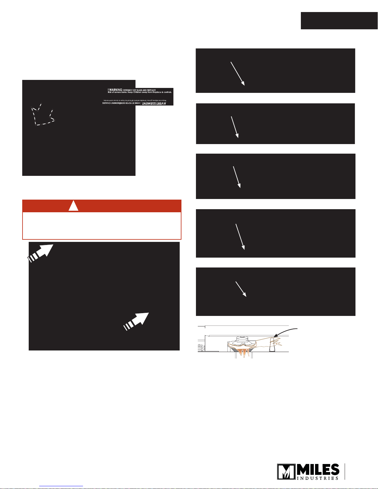
7. If the Hot Glass Warning plate has been removed
from the inner front lower corner of the barrier
screen, reinstall it by inserting it behind the
screen as indicated.
Hot Glass Warning Plate
8. Reinstall the barrier screen sliding it around the
fi rebox.
WARNING
!
FOR SAFETY PURPOSE, ensure the barrier
screen is re-installed on the fireplace after
maintenance.
Pilot Flame can be seen
towards the left side
Long Beach Driftwood Kit Correct Flame Picture
Pilot Flame can be seen
towards the left side
Murano Glass Fire Correct Flame Picture
Pilot Flame can be seen
towards the left side
Decorative Glass Set Correct Flame Picture
Pilot Flame can be seen
towards the left side
9. Verify that the screen is secure.
Checking Pilot and Burner Flames
A periodic check of the pilot and burner fl ames should
be made. Check after the fi re has been on for at least
30 minutes. The pilot fl ame must cover the tip of the
thermocouple probe. The main burner fl ame pattern will
vary from appliance to appliance depending on the type
of installation and climatic conditions.
Splitwood Kit Correct Flame Picture
Pilot Flame can be seen
towards the left side
Rock & Shale Kit Correct Flame Picture
Pilot Flame
Thermocouple Probe
must be in Flame
The appliance area must always be kept clear and
free from combustible materials, gasoline and other
fl ammable vapors and liquids.
Inspect the vent terminal outdoors regularly to make
sure that snow, trees, bushes, leaves, or other objects
do not obstruct it.
Examine the vent system and terminal regularly. We
recommend annually.
9

OWNER’S
INFORMATION
Owner’s Information
Replacing Batteries
The fi replace requires electrical power which will power
the upper lighting (supplied) as well as the remote
control receiver. The handset needs however, a battery.
If you wish to have batteries operating the
fi replace in case of a power outage, insert
batteries in the Remote battery and Wall
Switch (supplied) installed near the fi replace.
DO NOT PUT BATTERIES IN THE
RECEIVER OF THE FIREPLACE!
Battery
holder &
wall switch
They will overheat and leak.
CAUTION
DO NOT USE a screwdriver or other metallic object
to remove the batteries from the battery holder or
the handset! This could cause a short circuit.
Low batteries signal: see page 18.
BEFORE changing the batteries, turn the fi replace
off (including pilot).
The appliance uses four 1.5 V AA alkaline batteries
located next to the wall switch and one 9 V alkaline
battery in its handset. Batteries should last one to two
seasons, depending on usage. Removing the batteries
in the off -season will extend the battery life.
To replace the batteries:
The battery compartment is located next to the wall
switch in the vicinity of the fi replace. Its front plate is
attached with magnets to the wall switch box.
2. Disconnect the snap
connector from the
battery holder. Do not
pull the connector by
the wire!
3. Replace the batteries
with 4 AA alkaline
batteries orienting them
as indicated inside the
holder.
4. Reconnect the snap connector to the battery holder.
5. Put the battery holder back in its place beside the
wall switch and snap it in place.
Disconnect
connector
Using Remote Control Handset Wall Holder
Your fi replace equipment includes a wall
holder to store the handset. If it hasn’t be
installed, refer to the instructions further on
in this manual for the installation.
Replacing Light Bulbs
Overhead Lighting (3 light bulbs)
The appliance is equipped with a decorative lighting
located above the fuel bed. To replace the light bulbs,
follow these steps:
1. Remove the front glass window.
2. Locate the light fi xture above the fi rebed.
Fireplace
The battery holder is located beside the wall switch.
1. Pull on the plate next
to the wall switch to
access the batteries.
10
Battery
holder
& wall
switch
3. Turn off the lighting using the remote control handset.
4. Remove the burned light bulbs from their sockets
by gently pulling on them sideways.
5. With a gloved hand, replace with new light bulbs
using only a 20 watts halogen 120 volts
(type GY6.35 base bi-pin).
6. Test the bulbs by turning the lighting on.
NOTE: If the bulbs are new and not functioning,
turn off the remote control lighting and call your
dealer for inspection.
7. Reinstall the front window.
Owner’s Information
OWNER’S
INFORMATION
Underbed lighting (14 light bulbs) (if used)
If the 2200ULK—Underbed Lighting Kit has been
installed, your can replace the burned light bulbs in the
following manner.
1. Remove the front glass window.
2. Remove the fuel bed.
3. Remove the media trays, front and back (3 screws
each).
4. Locate the light fi xture below the fi rebed.
5. Turn off the underbed lighting using the wall dimmer
switch.
6. Remove the burned light bulbs from their sockets
by gently pulling on them towards the center.
7. With a gloved hand, replace with new light bulbs
using only a 20 watts halogen 120 volts
(type GY6.35 base bi-pin).
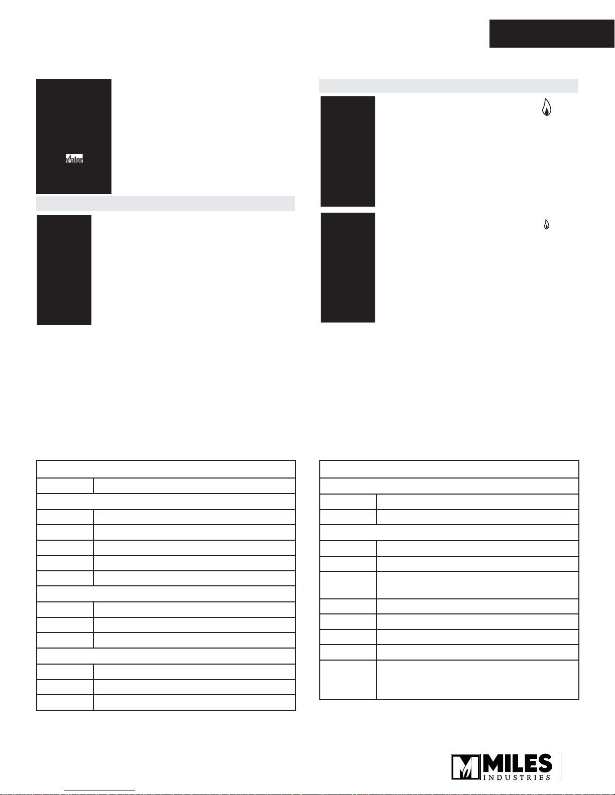
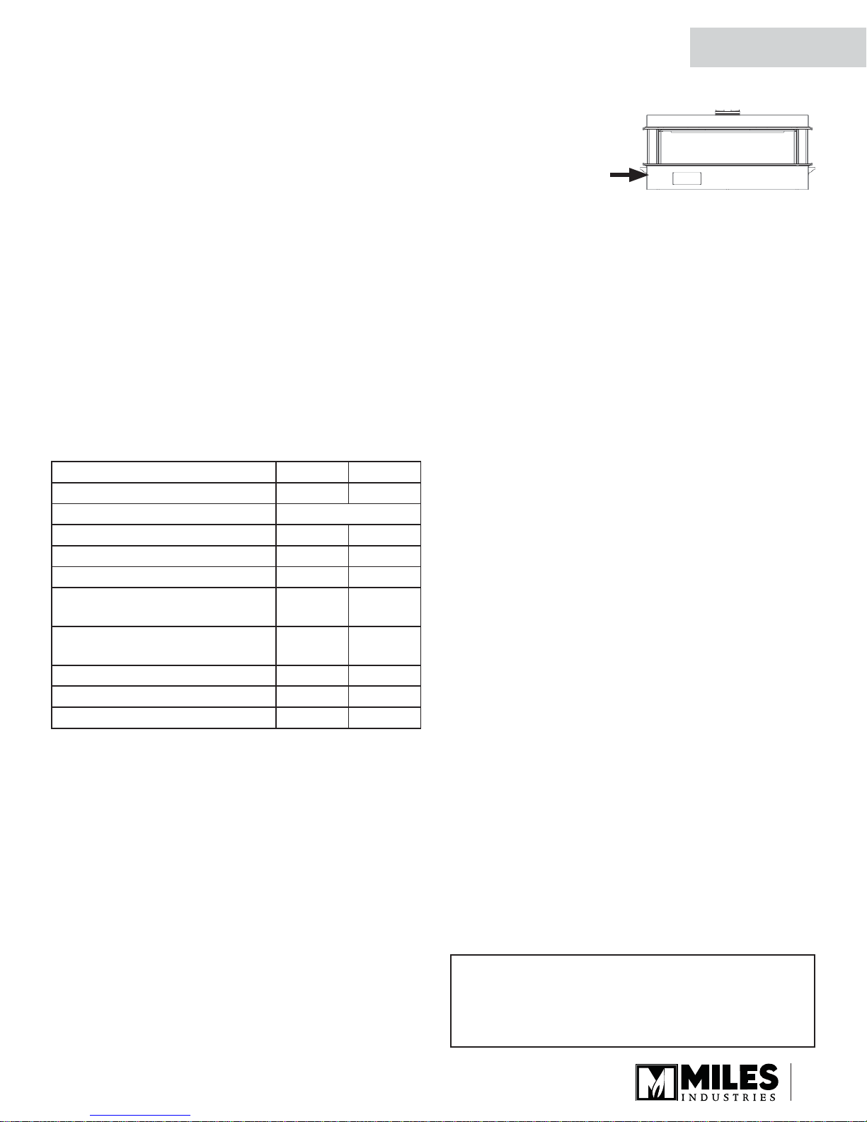
To access the card, remove the barrier screen. Grab
the card and pull it out. There is important information
on both sides of the card.
Window
The data card is located behind the front panel below
the window at the right-hand side.
Data
card
Servicing Your Fireplace
If any attention is required for your appliance, contact
your supplier quoting the model number. It will be
helpful if the appliance’s serial number can also
be quoted. This number is on the rating plate. The
replacement parts are shown at the end of this manual.
Please always quote the part number and description
when requesting spare parts.
8. Test the bulbs by turning the lighting on.
NOTE: If the bulbs are new and not functioning,
turn off the dimmer switch and call your dealer for
inspection.
9. Replace the media front and rear trays.
10. Reinstalle the fuel bed—see the instructions to
install the fuel beds in this manual.
11. Refi t the window.
Locating Lighting, Operation and Rating
Information Card
WARNING
!
DO NOT ATTEMPT TO TOUCH THE DATA CARD
WHILE THE FIREPLACE IS STILL HOT! Let the
fi replace cool fi rst before touching it.
The Lighting, Operation and Rating information is
located on a card at the right hand side of the fi replace
case. It is located under the barrier screen base.
Fireplace Control Devices
There are two ways to control your fi replace.
1. Thermostatic Remote
Control;
2. Wall Switch.
The Thermostatic Remote
Control can be programmed
to function automatically—
see pages 13–18.
The Wall Switch can be used to turn on, off and to
increase or decrease the fl ame height—see page 19.
Thermostatic
Remote Control
Wall Switch
How to Turn Your Fireplace OFF
(including pilot)
Familiarize yourself with each of these methods before
operating your fi replace.
Press and hold the OFF button for a second (either on
the handset or the wall switch).
Remote control handset
Wall Switch
11

OWNER’S
INFORMATION
Owner’s Information
If the fl ames are on, they go down and you hear the
valve motor wind down. You hear a clunk and a beep
indicating that the valve has received the signal from
the remote control.
As well, familiarize yourself with the gas shut-off valve
location in your house. As indicated below, the gas is
running when the handle is parallel with the pipe. The
gas is off when the handle is perpendicular with the pipe.
ON: parallel to pipe
OFF:
perpendicular
to pipe
How to Ensure Your Fireplace Cannot
Be Turned ON Inadvertently
You can do the following to ensure that your fi replace
will not turn on when you don’t want it on.
First, ensure your fi replace is turned off —including
the pilot—and cold BEFORE going ahead.
Turn the shut-off valve from the ON position (handle
parallel) to the OFF position (handle perpendicular) as
shown. This will cut off the gas supply to the fi replace
and will ensure that the main burner can not come on.
NOTE: Ensure shut-off valve is turned back to
ON position (handle parallel) before operating
the fi replace.
Automatic Shut-Off (in certain conditions)
Your fi replace’s remote control is equipped with an
automatic shut-off mechanism which is activated in
certain conditions. See page 18 in the Remote Control
Operation section for a description of this feature.
Gas
shut-off
valve
The gas shut-off valve is located behind the
front panel, left of the gas valve.
Fireplace
Gas valve
Turn off gas supply to the fi replace. Access the gas
shut-off valve by removing the barrier screen. The shutoff valve is located behind the front panel on the left of
the gas valve as indicated.
Gas shut-off valve
Top view
12
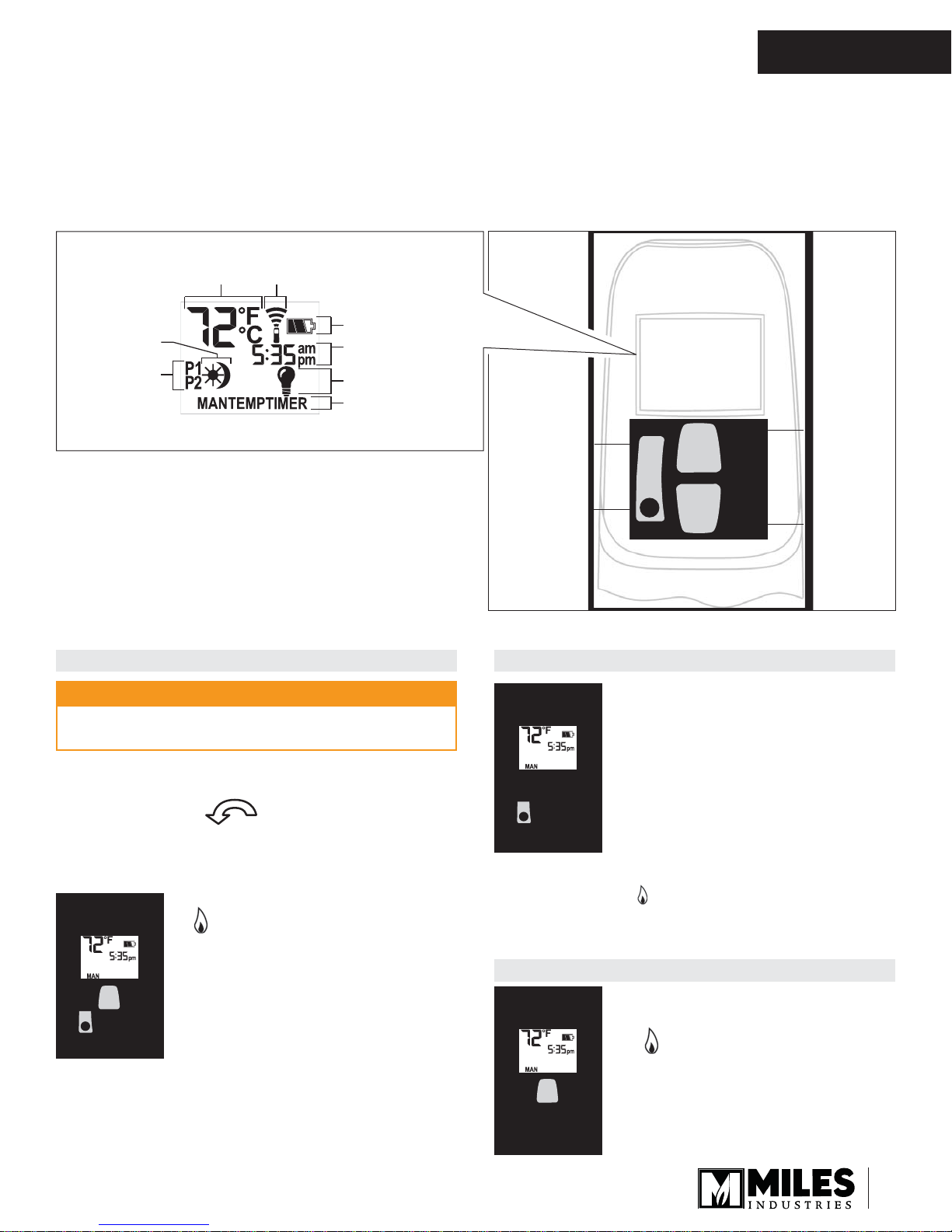
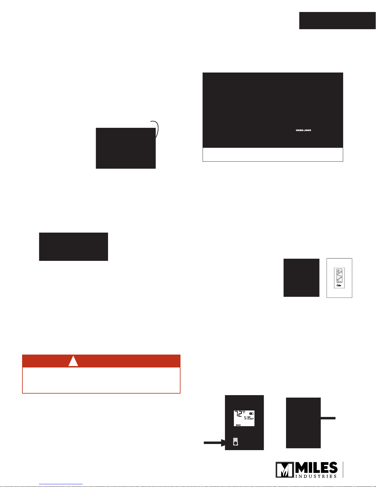
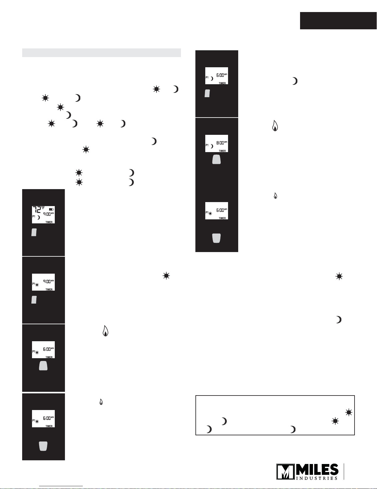
Remote Control Operation
Current
temperature
(F or C)
Current time
(12 or 24 hour clock)
Modes (Manual,
Temperature, Timer)
Handset
sensor
Battery status
Current
programmed
period (Timer)
Period
start or end
(Temp, Timer)
Top Lighting
OWNER’S
INFORMATION
NOTE: Before using the remote control system for
the fi rst time, the receiver and the handset must be
synchronized. See the section Initialize Remote Control
on page 45 of this manual.
Display Overview
Note: In the TEMP or TIMER modes, the remote
handset senses the room temperature and adjusts the
fl ame accordingly.
To communicate, the handset should be within 15 feet
(4.5 meters) of the fi replace.
Do not leave the handset on the mantel or hearth.
IMPORTANT: BEFORE YOU BEGIN, please note that
on this system, the settings of time, temperature and
automatic ON/OFF can only be programmed when
the function display is fl ashing. Be patient when
programming as it can take a few seconds to set.
Large ame
Set (scrolls
through
modes and
settings)
OFF (returns
to set mode,
turns the burner
and the pilot o)
Handset Overview
button (ames
up, sets hours,
temperature)
Small ame
button (ames
down and o,
sets minutes,
temperature)
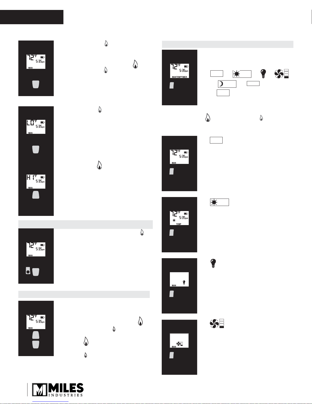
TO TURN ON APPLIANCE TO TURN OFF APPLIANCE
CAUTION
When pilot ignition is confi rmed, motor turns
automatically to maximum fl ame height.
• On the valve, turn MAN knob on the ON, full
counterclockwise position.
• Place ON/OFF switch (if equipped) in I (ON
position).
• Simultaneously press the OFF and
(large fl ame) buttons until a short
beep confi rms the start sequence
has begun; release buttons.
• Continuing beeps confi rm the
ignition is in process.
• Once pilot ignition is confi rmed,
there is main gas fl ow.
• After main burner ignition the
handset will automatically go into
manual (MAN) control mode.
• Press OFF button.
When the pilot is off , it will take 2
When the pilot is off , it will take 2
minutes before it can be lit again.
minutes before it can be lit again.
STANDBY MODE (Pilot Flame)
• Press and hold (small fl ame) to set appliance at
pilot fl ame.
FLAME HEIGHT ADJUSTMENT
• In standby mode: Press and hold
(large fl ame) button to increase
fl ame height.
13
OWNER’S
INFORMATION
Remote Control Operation
• Press and hold (small fl ame)
button to decrease fl ame height or
to set the appliance at pilot fl ame.
• For fi ne adjustment tap the
(large fl ame) or (small fl ame)
buttons.
Express Low and High Fire
• Double-click (small fl ame)
button. “LO” will be displayed.
NOTE: Flame goes to high fi re fi rst
before going to designated low fi re.
x 2
• Double-click (large fl ame)
button. Flame automatically goes
to high fi re. “HI” will be displayed.
MODES OF OPERATION
• Briefl y pressing the SET button
changes the mode of operation in
the following order:
MAN
→ → →
→ → → and back
TEMP
MAN
to .
NOTE: Manual mode can also be reached by pressing
either the (large fl ame) or the (small
fl ame) buttons.
MAN
• - Manual Mode - Manual
Flame Height Adjustment.
TEMP
TIMER
x 2
SETTING ºC/24-HOUR OR ºF/12-HOUR CLOCK
• In MAN mode, press OFF and
(small fl ame) buttons until display
changes from Farenheit/12-hour
clock to Celsius/24-hour clock and
vice versa.
SETTING THE TIME
• The time display will fl ash after
either:
◊ Installing the battery or
◊ Simultaneously pressing the
(large fl ame) and (small
fl ame) buttons.
• Press (large fl ame) button to
set the hour.
• Press (small fl ame) button to
set the minute.
• Press OFF or simply wait to return
to MAN mode.
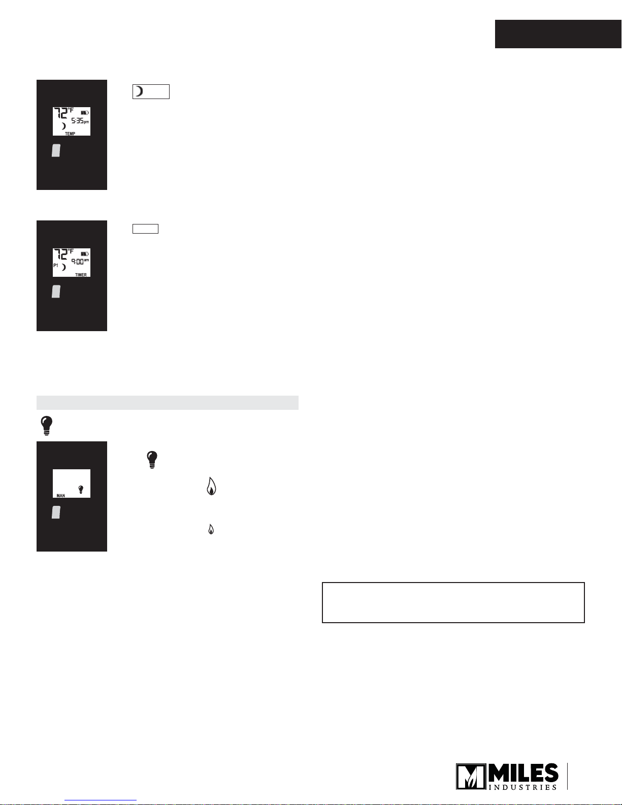
TEMP
• - Daytime Tempera-
ture Mode (Appliance must be in
standby mode; pilot ignited) - The
room temperature is measured and
compared to the set temperature.
The fl ame height is then automatically adjusted to achieve the
Daytime Set Temperature.
• - Light/Dimmer Setting Mode
Turns light/dimmer ON and OFF
and adjust brightness.
• - Fan Mode
Not available on this fi replace.
14
Remote Control Operation
TEMP
• - Nighttime Setback
Temperature Mode (Appliance
must be in standby mode; pilot
ignited) - The room temperature
is measured and compared to the
Nighttime Setback temperature.
The fl ame height is then automatically adjusted to achieve the Nighttime Setback Temperature.
TIMER
• - Timer Mode (Appliance
must be in standby mode; pilot
ignited) - The timers P1 and P2
(Program 1, Program 2) each can
be programmed to go ON and OFF
at specifi c times. For instructions
see Timer Programming Mode.
OWNER’S
INFORMATION
NOTE: The display shows the set temperature every
30 seconds.
LIGHT/DIMMER OPERATION (FIREBOX TOP)
- Light/Dimmer
• Briefl y press SET button to scroll
to (light bulb) mode. Light bulb
icon fl ashes.
• Press and hold (large fl ame)
button to turn ON the light or
increase brightness.
• Press and hold (small fl ame)
button to decrease brightness.
NOTE: The light bulb icon is displayed during light/
dimmer setting only. 8 seconds after the
light/dimmer has been set, the handset will
automatically go into temperature control
mode.
Tip
Set the diff erent parameters when they are fl ashing.
15
OWNER’S
INFORMATION
Remote Control Operation
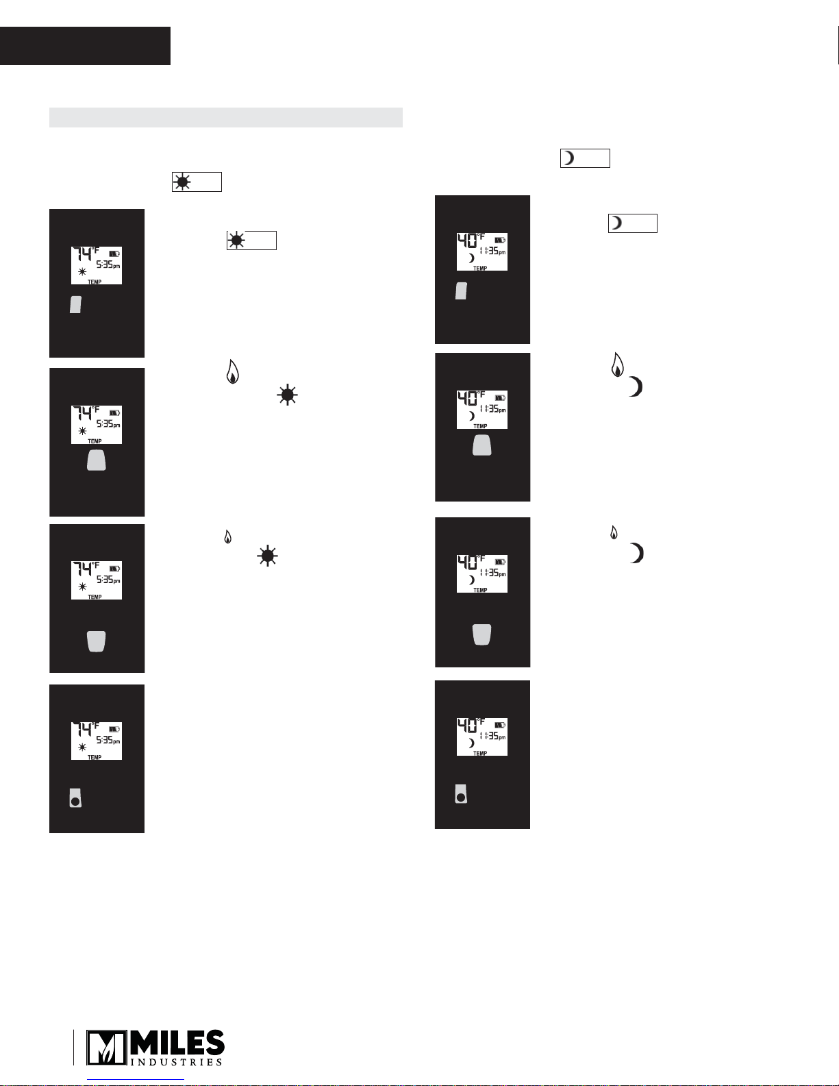
SETTING THE ON / OFF TEMPERATURES
SETTING THE “DAYTIME” TEMPERATURE
Default Settings: (sun), 23ºC / 74ºF
TEMP
• Briefl y press SET button to scroll to
TEMP (sun) mode. Hold
TEMP
the SET button until the TEMP
fl ashes.
• Press (large fl ame) button
to increase the Daytime Set
Temperature.
SETTING THE “NIGHTTIME SETBACK”
TEMPERATURE
Default Settings: (moon), “--” (OFF)
TEMP
• Briefl y press SET button to scroll to
TEMP (moon) mode. Hold
TEMP
the SET button until the TEMP
fl ashes.
• Press (large fl ame) button to
increase Nighttime Setback
Temperature.
• Press (small fl ame) button
to decrease Daytime Set
Temperature.
• Press OFF or simply wait to
complete programming.
• Press (small fl ame) button to
decrease Nighttime Setback
Temperature.
• Press OFF or simply wait to
complete programming.
16
Remote Control Operation
OWNER’S
INFORMATION
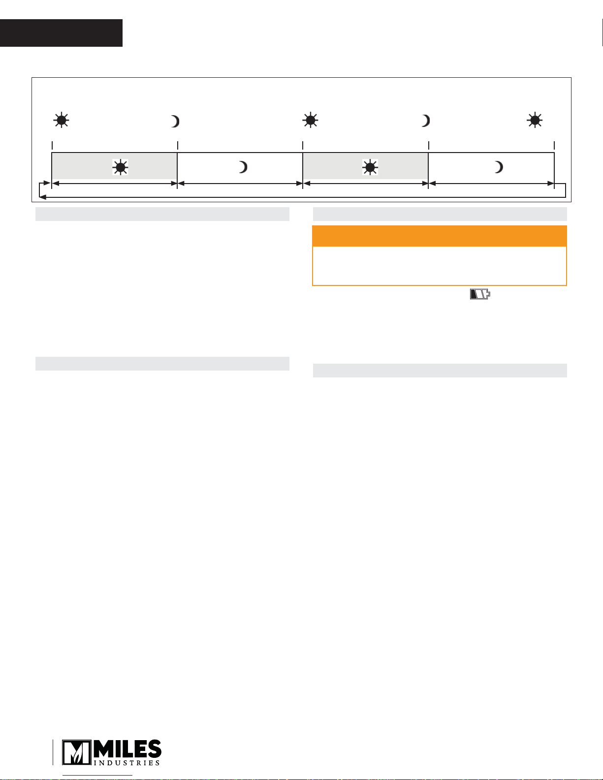
SETTING PROGRAM TIMERS
• You can program two periods of time between 12:00
am and 11:50 pm in each 24-hour cycle.
• The Programs P1 and P2 must be set in the
following order during a 24-hour cycle: , ,
P2
and .
• The icon indicates the beginning of the period (ON)
and the icon indicates the end of the period (OFF).
P1
• If = or = , the programming
is cancelled.
• To keep the fi replace ON all night, set at
11:50 am and at 12:00 am.
P1
P2
P1
P2
P2
P1
P2
Default settings:
Program 1: 6:00 am 8:00 am
Program 2: 11:50 pm 11:50 pm
P1
P2
• Briefl y press SET button to scroll to
TIMER mode.
P1
P2
P1
SETTING P1 OFF TIME
• Briefl y press SET button to scroll
to TIMER (moon) while the
time fl ashes.
• Press (large fl ame) button to set
the hour.
• Press (small fl ame) button to
set the minutes.
P1
SETTING P1 ON TIME
• Hold the SET button until
(sun) is displayed and the time
fl ashes.
• Press (large fl ame) button to
set the hour.
• Press (small fl ame) button to
set the minutes.
P1
SETTING P2 ON TIME
• Briefl y press SET to scroll to TIMER mode
(sun) while the time fl ashes.
• Follow the instructions given to set P1 ON time.
P2
SETTING P2 OFF TIME
• Briefl y press SET to scroll to TIMER mode
(moon) while the time fl ashes.
• Follow the instructions given to set P1 OFF time.
Press OFF button to save these settings. The timers
are programmed. See the diagram on programming
sequences on the following page.
P2
Tip
If you want to program only one period, program
and with desired times and program and
P1
P2
with the same time as .
P1
P1
P2
17
OWNER’S
INFORMATION
Timer Programming Example (default temperatures shown)
Remote Control Operation
6:00 a.m.—
P1
Start time
Set temp 74˚F Set temp 40˚FSet temp 74˚F
8:00 a.m.—
P1
End time
Set temp 40˚F
AUTOMATIC TURN DOWN
• No communication. If there is no communication
between the receiver and the handset for a period of 6
hours, the appliance goes into pilot mode.
• No change in fl ame height. If there is no change
in fl ame height for a period of 6 hours, the appliance
goes into pilot mode.
NOTE: In TEMP or TIMER modes, the fl ame height
will vary according to room temperature. The appliance
will continue to work normally. However, if the room
temperature remains the same for 6 hours, the appliance will go into pilot mode.
AUTOMATIC SHUT OFF
• Low batteries in the remote battery holder. With low
battery power in the remote battery holder the system
shuts off completely.
NOTE: This does not apply when the power supply is
interrupted.
• No change in pilot. The appliance shuts off
completely when it is continually in pilot position—
without any change—for a period of 5 days.
4:00 p.m.—
P2
Start time
LOW BATTERY INDICATION
DO NOT USE a screwdriver or other metallic object
to remove the batteries from the battery box or the
handset! This could cause a short circuit.
Remote handset: The battery icon will show when
the battery needs to be replaced. Replace with one 9 V
alkaline battery.
Remote battery holder: Frequent ‘beeps’ for 3 seconds
when the valve motor turns indicate the batteries need to
be replaced. Replace with four 1.5 V alkaline batteries.
HANDSET / RECEIVER MATCH
The remote control handset and receiver are programmed to
function together. In case of a replacement of the handset or
the receiver, you will need to reset the receiver to allow them
to function together. Contact your dealer for details.
10:00 p.m.—
P2
End time
CAUTION
6:00 a.m.—
P1
Start time
18
Wall Switch Operation
OWNER’S
INFORMATION
The Wall Switch can be used to
control your fi replace. You can
turn the pilot on or off and you can
increase or decrease the fl ame
height.
Note that the thermostat and
programming functions are not
available with the wall switch.
TO TURN APPLIANCE ON and OFF
• Press ON-OFF button once to light
pilot. Press again to shut of pilot.
TO ADJUST FLAME HEIGHT
• Press and hold large fl ame
button to gradually increase
fl ame height.
• Press and hold small fl ame
button to gradually decrease
fl ame height.
Required Kits*
4006222 LX2 Barrier Screen
Fuel Beds (choose one)
1705DWK Driftwood Set Kit
2200DGM Murano Glass Set
2200DGS Decorative Glass Set
1700SWK Splitwood Kit
1700RSS Rocks & Shale Set
Liners (choose one)
2200FBL Fluted Black Liner Set
2200RGL Refl ective Glass Liner Set
2200LML Limestone Liners
LDK HeatShift (choose one)
LDK1 Quad Plenum 48”
LDK3 Double Plenum 14” (2) with Grille
LDK4 Quad Plenum 38”
Kits & Accessories
Optional Accessories*
Conversion Kits
2200NGK Conversion to natural gas
2200PGK Conversion to propane gas
Other Accessories
LDK2 48” Finishing Frame for LDK1
LDK5 38” Finishing Frame for LDK4
LDK6
2200ULK Underbed Lighting Kit (for 2200DGS)
1270RBK Remote Blower Kit
2200USB Upper Shelf Black
2200LSB Lower Shelf Black
Hearth
Gate
5” dia Aluminum 2-ply Flex Kit— 2 x 10’–0”
lengths, may be cut to required length
Hearth gates such as Cardinal’s
VersaGates are available at retail stores
carrying safety products for children.
*Information accurate at the time of printing and subject to change without notice.
19
OWNER’S
INFORMATION
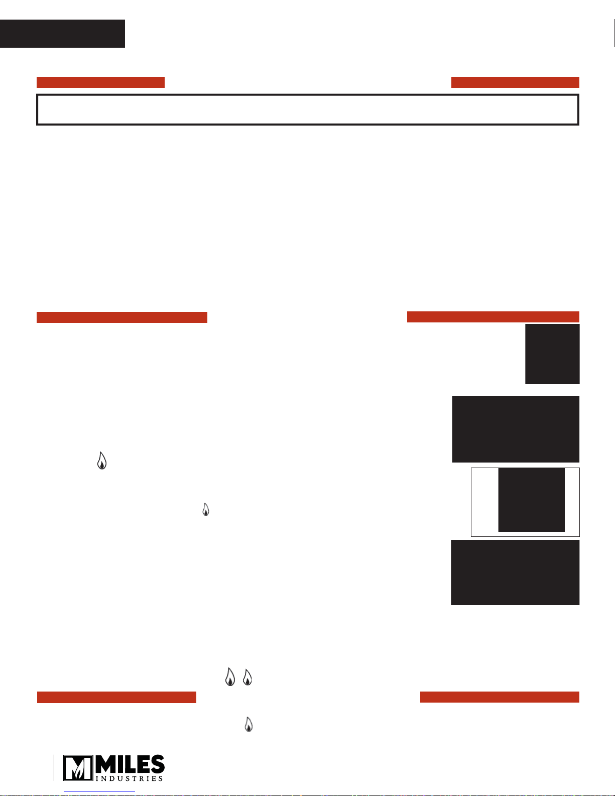
Lighting Instructions
FOR YOUR SAFETY, READ BEFORE LIGHTING
WARNING: If you do not follow these instructions exactly, a fi re or explosion may result
causing property damage, personal injury or loss of life.
A. This appliance has a pilot which must be lighted by hand, remote control, or wall switch. Follow these instructions
exactly. To save gas, turn the pilot off when not using the appliance for a prolonged period of time.
B. BEFORE LIGHTING, smell all around the appliance area for gas. Be sure to smell next to the fl oor because
some gases are heavier than air and will settle on the fl oor.
WHAT TO DO IF YOU SMELL GAS
• Do not try to light any appliance.
• Do not touch any electric switch; do not use any phone in your building.
• Immediately call your gas supplier from a neighbor’s phone. Follow the gas supplier’s instructions.
• If you cannot reach your gas supplier, call the fi re department.
C. Use only your hand to push in or turn the control knobs. Never use tools. If the knobs will not push in or turn by
hand, don’t try to repair them; call a qualifi ed service technician. Force or attempted repair may result in a fi re or
explosion.
D. Do not use this appliance if any part has been under water. Immediately call a qualifi ed service technician to
inspect the appliance and to replace any part of the control system and any gas control, which has been under water.
LIGHTING INSTRUCTIONS
1. STOP! Read the safety information above.
2. TO CLEAR ANY GAS, turn main valve off by pressing OFF (red dot) button on remote handset
(1).
• Wait fi ve (5) minutes to clear out any gas, then smell for gas, including near the fl oor. If you
smell gas, STOP! Follow “B” in the safety information above on this label. If you don’t smell
gas, go to the next step.
3. AUTOMATIC IGNITION: MAN-knob (2) in ON position. Ensure Flame Adjustment
Fig 1
knob (3) is set to lowest setting () (Fig. 1). Locate the pilot (Fig. 3.) inside of
fi rebox at left hand side.
• On the remote control handset, press the OFF button (red dot) and large fl ame
button () simultaneously; a short acoustic signal confi rms the start has begun.
• Further short acoustic signals indicate the ignition process is in progress.
• When the pilot is lit, the Flame Adjustment knob (3) will automatically rotate to
the highest setting.
• Press the small fl ame button () on the remote control handset to reduce the
fl ame height.
4. MANUAL IGNITION: MAN-knob (2) in MAN position (Fig. 2). With the window
off , locate the pilot (Fig. 3) inside of fi rebox at left hand side.
Fig 3
Fig 2
• Set Flame Adjustment knob (3) to the lowest setting ().
• Push down the metallic core (4) with a pen or similar instrument; this will establish
the pilot gas fl ow.
• Light gas at the pilot (5) with a match.
• Continue holding down metal core (4) for about 10 seconds; after release, pilot
should remain lit.
• If the pilot will not stay lit after several tries, turn the gas control knob (3) to OFF () and call your local
service technician or gas supplier.
• Reinstall the window and set the MAN-knob (2) to ON; turn Flame Adjustment knob (3) up () or down ()
manually or use the fl ame buttons on the remote control handset to adjust the fl ame height.
1
OFF
Spark
5
Pilot
AUTOMATIC SHUT-OFF (using the remote control handset):
• Press and hold the small fl ame button () on the remote control handset to shut-off the main burner gas fl ow.
• Press OFF button (red dot) on remote handset to shut-off the appliance, including pilot fl ame.
20
TO TURN OFF GAS TO APPLIANCE

Commonwealth of Massachusetts
QUALIFIED
INSTALLER
State of Massachusetts Carbon Monoxide
Detector/Vent Terminal Signage
Requirements
For all side wall horizontally vented gas fueled
equipment installed in every dwelling, building or
structure used in whole or in part for residential
purposes, including those owned or operated by the
Commonwealth and where the side wall exhaust
vent termination is less than seven (7) feet above
fi nished grade in the area of the venting, including
but not limited to decks and porches, the following
requirements shall be satisfi ed:
1. INSTALLATION OF CARBON MONOXIDE
DETECTORS. At the time of installation of the side wall
horizontal vented gas fueled equipment, the installing
plumber or gas fi tter shall observe that a hard wired
carbon monoxide detector with an alarm and battery
back-up is installed on the fl oor level where the gas
equipment is to be installed. In addition, the installing
plumber or gas fi tter shall observe that a battery
operated or hard wired carbon monoxide detector
with an alarm is installed on each additional level of
the dwelling, building or structure served by the side
wall horizontal vented gas fueled equipment. It shall
be the responsibility of the property owner to secure
the services of qualifi ed licensed professionals for the
installation of hard wired carbon monoxide detectors.
a. In the event that the side wall horizontally vented
gas fueled equipment is installed in a crawl space or
an attic, the hard wired carbon monoxide detector with
alarm and battery back-up may be installed on the next
adjacent fl oor level.
b. In the event that the requirements of this subdivision
can not be met at the time of completion of installation,
the owner shall have a period of thirty (30) days
to comply with the above requirements; provided,
however, that during said thirty (30) day period, a
battery operated carbon monoxide detector with an
alarm shall be installed.
shall be permanently mounted to the exterior of the
building at a minimum height of eight (8) feet above
grade directly in line with the exhaust vent terminal for
the horizontally vented gas fueled heating appliance
or equipment. The sign shall read, in print size no less
than one-half (1/2) inch in size, “GAS VENT DIRECTLY
BELOW. KEEP CLEAR OF ALL OBSTRUCTIONS”.
4. INSPECTION. The state or local gas inspector of
the side wall horizontally vented gas fueled equipment
shall not approve the installation unless, upon
inspection, the inspector observes carbon monoxide
detectors and signage installed in accordance with the
provisions of 248 CMR 5.08(2)(a)1 through 4.
(b) EXEMPTIONS: The following equipment is exempt
from 248 CMR 5.08(2)(a)1 through 4:
1. The equipment listed in Chapter 10 entitled
“Equipment Not Required To Be Vented” in the most
current edition of NFPA 54 as adopted by the Board;
and
2. Product Approved side wall horizontally vented
gas fueled equipment installed in a room or structure
separate from the dwelling, building or structure used in
whole or in part for residential purposes.
(c) MANUFACTURER REQUIREMENTS - GAS
EQUIPMENT VENTING SYSTEM PROVIDED.
When the manufacturer of Product Approved side
wall horizontally vented gas equipment provides a
venting system design or venting system components
with the equipment, the instructions provided by the
manufacturer for installation of the equipment and the
venting system shall include:
1. Detailed instructions for the installation of the venting
system design or the venting system components; and
2. A complete parts list for the venting system design or
venting system.
2. APPROVED CARBON MONOXIDE DETECTORS.
Each carbon monoxide detector as required in
accordance with the above provisions shall comply
with NFPA 720 and be ANSI/UL 2034 listed and IAS
certifi ed.
3. SIGNAGE. A metal or plastic identifi cation plate
(d) MANUFACTURER REQUIREMENTS - GAS
21

QUALIFIED
INSTALLER
EQUIPMENT VENTING SYSTEM NOT PROVIDED.
When the manufacturer of a Product Approved side
wall horizontally vented gas fueled equipment does
not provide the parts for venting the fl ue gases, but
identifi es “special venting systems”, the following
requirements shall be satisfi ed by the manufacturer:
1. The referenced “special venting system” instructions
shall be included with the appliance or equipment
installation instructions; and
2. The “special venting systems” shall be Product
Approved by the Board, and the instructions for that
system shall include a parts list and detailed installation
instructions.
(e) A copy of all installation instructions for all Product
Approved side wall horizontally vented gas fueled
equipment, all venting instructions, all parts lists
for venting instructions, and/or all venting design
instructions shall remain with the appliance or
equipment at the completion of the installation.
Commonwealth of Massachusetts
22
Specifi cations
QUALIFIED
INSTALLER
Approval & Codes
This appliance is certifi ed to ANSI Z21.88-2014/CSA
2.33-2014 American National Standard / CSA Standard
for Vented Gas Fireplace Heaters for use in Canada
and USA, and to CGA 2.17-91 High Altitude Standard in
Canada. This appliance is for direct vent installations.
This appliance complies with CSA P.4.1-15 Testing
method for measuring annual fi replace effi ciencies.
The installation must conform to local codes or, in the
absence of local codes, with the National Fuel Gas Code,
ANSI Z223.1/NFPA 54 or the Natural Gas and Propane
Installation Code CAN/CGA-B149.1. Only qualifi ed
licensed or trained personnel should install this appliance.
This appliance must be electrically grounded in
accordance with local codes, or, in the absence of local
codes, with the National Electrical Code, ANSI/NFPA
70 or the Canadian Electrical Code, CSA C22.1.
Ratings
Model JN JP
Gas Natural Propane
Altitude (Ft.)* 0-4,500 feet*
Input Maximum (Btu/h) 36,000 36,000
Input Minimum (Btu/h) 19,000 21,000
Manifold Pressure (in w.c.) 3.5” 10”
Minimum Supply Pressure
(in w.c.)
Maximum Supply Pressure
(in w.c.)
Main Burner Injector Marking 1000 50
Pilot Injector Marking 51 30
Min. Rate By-Pass Screw 220 160
5” 11”
10” 14”
*High Altitude Installations
Input ratings are shown in BTU per hour and are
certifi ed without deration for elevations up to 4,500 feet
(1,370 m) above sea level.
For elevations above 4,500 feet (1,370 m) in USA,
installations must be in accordance with the current
ANSI Z223.1 and/or local codes having jurisdiction.
Heating value of gas in some areas is reduced to
compensate for elevation—consult your local gas
utility to confi rm.
For installations at elevations above 4,500 feet
(1,370 m) in Canada, please consult provincial and/or
local authorities having jurisdiction.
Supply Gas
Heater engine 2200JN is used with natural gas.
Heater engine 2200JP is used with propane gas.
The supply pressure
must be between the
limits shown in the
Ratings section above.
The supply connection
is 1/2” NPT male and
located on the rear left side of the fi rebox. A shut-off
valve (supplied) is required on the supply line to isolate
the unit during service. See Supply Gas Installation
section for details.
X
Conversion Kits
The 2200J LX2 is supplied as natural gas or propane gas
and is fi eld convertible between fuels. See instructions
packaged with the conversion kit for further information.
Electrical
The 2200J is designed to run on battery power and
does not require an electrical power source to operate
as a heater. However, it requires electrical power to
operate the interior lighting, the optional 2200ULK
Underbed Lighting Kit or 1270RBK Remote Blower Kit.
LDK HeatShift Duct Kit
The 2200J must be installed with the LDK HeatShift
Duct Kit, a convection system that redistributes the
warm air fl ow away from the fi replace opening to a
more desirable location using natural convection,
without use of a fan.
The warm air fl ow may be relocated to a position higher
up the wall, out the sidewalls, or even to another room.
The result is much cooler wall temperatures above the
fi replace opening for locating televisions, artwork, etc.
Please note that the framing and mantel clearances
are aff ected by the installation of the LDK. Refer
to the installation manual packed with the kit for more
information.
This appliance is designed and approved as a
supplemental heater and provides the potential
for most energy conservation when used while
attended. The use of an alternate primary heat
source is advisable.
23
 Loading...