

Valor 2100SFK, LX1 Series Installation Manual
INSTALLATION MANUAL
LX1 Series
2100SFK Steel Framing Kit
For use with Valor 2100PK model fi replaces only
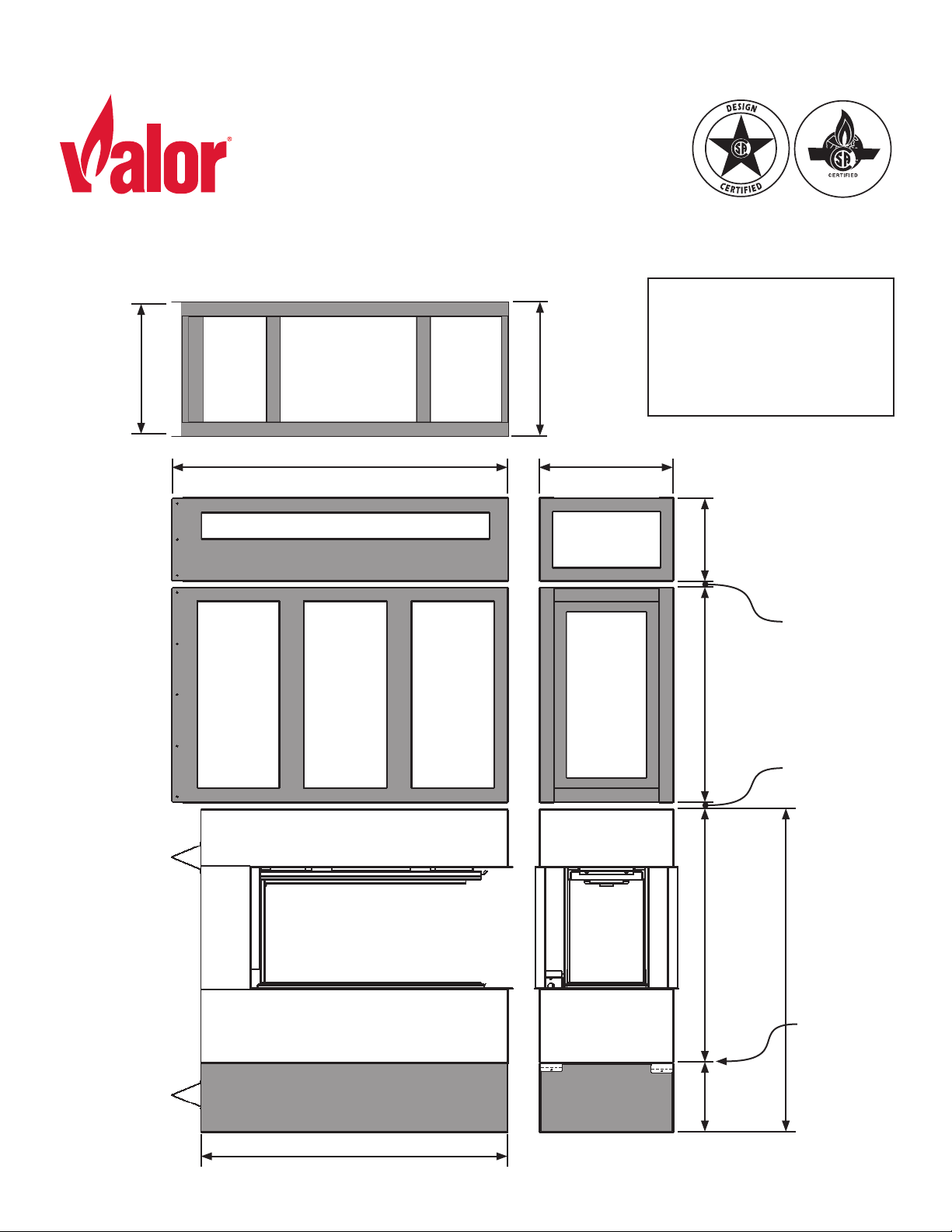
Minimum overall installed
18-7/16”
[468 mm]
between
fl anges
Side View Front View
Top View
46-3/4” [1187 mm]
(to wall)
18-1/2”
[470 mm]
outside of
fl anges
18-1/2”
[470 mm]
height (including minimum
separations above and below
middle section):
87-1/16” [2211 mm]
11-5/8”
[295 mm]
30”
[762 mm]
35-5/16”
[897 mm]
Minimum
separation
1/4” [7 mm]
Minimum
separation
1/4” [7 mm]
44-15/16”
[1142 mm]
4007778-01
©2019, Miles Industries Ltd.
42-11/16” [1085 mm]
9-5/8”
[245 mm]
Fireplace
rests directly
on base (feet
and standoff s do not
add height)
Installation
Steel Framing Kit
Before Installing the SFK
Prior to installation of the 2100SFK Steel Framing Kit,
ensure that the following items have already been
installed or roughed in. Installing these items after SFK
installation can be diffi cult:
• Any required wall thimble
• Any required insulation
• Drywall
• Rough electrical
• Rough gas
Also remove all barriers and windows.
Do not complete venting until after SFK installation.
Top Section
Required for Assembly
To complete these instructions, you will need:
• 2100SFK kit and 2100PKN or 2100PKP fi replace
• 2 kiln dried wood studs, cut to planned height
• wood screws and self drilling sheet metal screws (see
below)
The screws for assembly of the kit pieces are included.
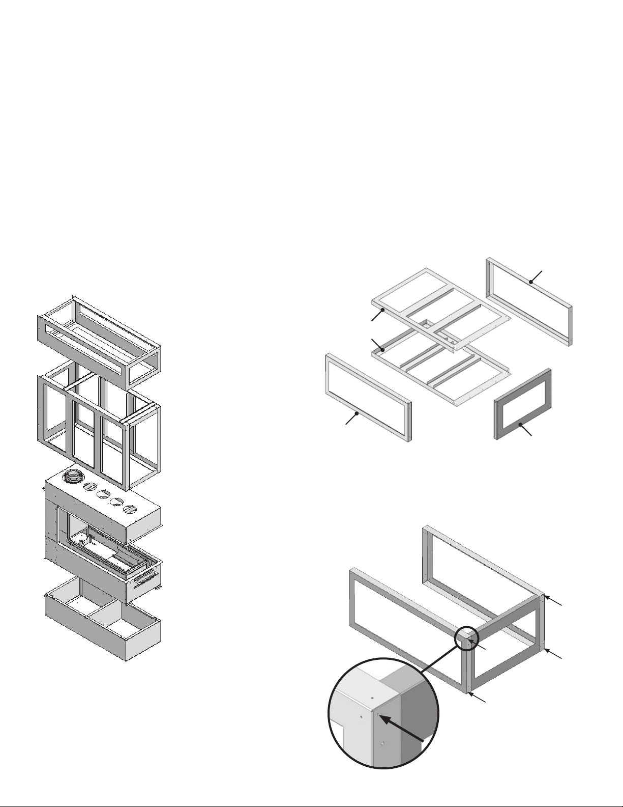
Assemble Middle Section
1. Locate the pieces that make up the middle section:
Top panel
(same as
bottom)
Side panels (2 same)
Middle Section
(requires assembly)
Fireplace
Bottom Section
Major Components
Note: The fi replace sits directly on the bottom section.
The middle section will be shimmed a minimum 1/4”
above the fi replace, and the top section will be shimmed
a minimum of 1/4” above the middle section. Clearance
between fi replace, middle section, and top section may
be increased to vary total installed height.
Bottom panel
(same as top)
2. Attach end panel to top and bottom panels (top and
bottom are identical). Use only the four outermost
screws indicated (these are temporary and will be
removed in step 5, allowing proper connection of the
middle section to the wall studs).
End panel
2
Installation
Steel Framing Kit
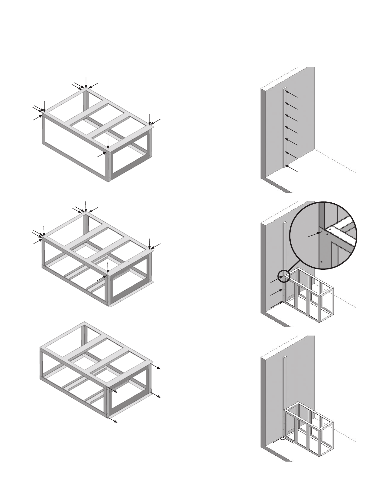
3. Place one of the side panels (both sides are identical)
on top of the assembly and screw together (12
screws, fi lling indicated available holes).
4. Flip assembly over and place other side panel on top
of the assembly. Screw together (12 screws).
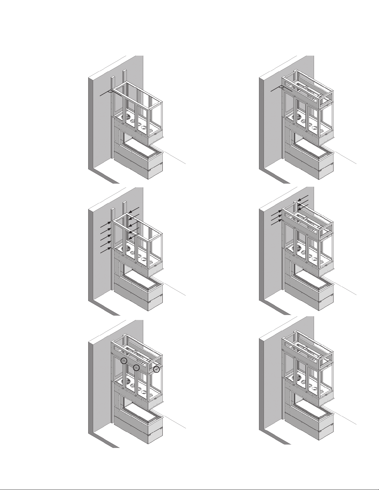
Install SFK and Fireplace
1. Place left hand
stud (cut to
planned installation height, not
included) vertically
and fl at against
wall. Level and
attach to stud
behind wall. Screw
every foot to
planned height.
Suggested #10 x
3-1/2” general purpose wood screws,
not included.
2. Use middle section on ground as
a guide for placing
right hand stud.
Screw middle section to left stud,
snug to wall (this is
temporary). Suggested #8 x 1-1/2”
general purpose
wood screws, not
included.
5. Remove the fi rst 4 screws from Step 2. This will allow
proper connection of the middle section to the wall.
6. Put the fi nished middle section aside.
3. Check square of
middle section
against wall.
90°
3

Installation
Steel Framing Kit
4. Fix right stud (not
included) to middle
section (Distance
is 18-7/16” to the
outside of both
studs).
5. Fix right stud to
stud behind wall.
Screw every foot
to planned height
above middle section.
18-7/16”
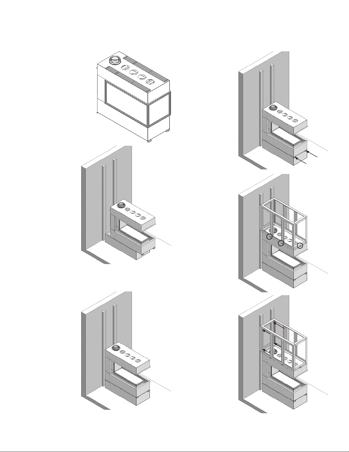
7. Rem ove mid dle
section from studs
and pull away
from wall. Screw
right stud to wall
where previously
covered.
8. Place bottom section against wall,
standoff s between
studs and corners
inside the fl oor
marks. Check for
square (perpendicular to wall).
6. Mark corners of
middle section on
fl oor.
4
90°
9. Screw bottom
section to fl oor (4
screws).
Installation
Steel Framing Kit
10. Remove four top standoff s from fi replace and
discard.
11. Place fi replace
on top of bottom
section but do not
place against wall.
X
X
X
X
14. Flatten front
feet of fi replace
down and screw
feet to the bottom section with
self-drilling sheet
metal screws (max
1” length).
15. Place shims on top
of the fi replace,
avoiding placing the shims on
screw heads (min
1/4”). Place middle
section on top
of fi replace with
fl anges around the
wall studs.
12. Stop and fi nish electrical and gas installation while
you have room (see “Electrical Wiring” and “Gas Supply” in the LX1 Installer’s Manual).
13. Once complete,
place fi replace
fully against the
wall (standoff s
between studs).
16. Screw the middle
section in line to
the wall, through
the studs, to pull
the middle section
snug against the
studs.
5
Installation
Steel Framing Kit
17. Check square on
middle section
and adjust if necessary.
18. Screw the middle
section to the outside of the studs
from each side (5
per side).
90°
20. Check square on
top section.
90°
21. Screw the top section to the studs
from each side (3
per side).
19. Place shims on
top of the middle
section, avoiding
placing the shims
on screw heads
(min 1/4”). Place
top section on top
of middle section.
Note: you may
want to place any
required HeatShift components
before placing
the top section,
see LX1 Installer’s
Manual for details.
6
22. If the studs were
not cut to planned
installation height,
cut off the visible
tops of the studs
now (if top venting
with LDK7 or leaving top clearance
above the wall
fi nish).
 Loading...