

Valor L1 Series, 1600JP, 1600JN Installation & Owner's Manual
INSTALLATION & OWNER’S MANUAL
L1 Series
Direct Vent Zero Clearance Gas Fireplaces
1600JN (natural gas) & 1600JP (propane gas)
Please read this manual
!
DANGER
HOT GLASS WILL
CAUSE BURNS.
BEFORE installing and
operating this appliance.
DO NOT TOUCH GLASS
UNTIL COOLED.
NEVER ALLOW CHILDREN
TO TOUCH GLASS.
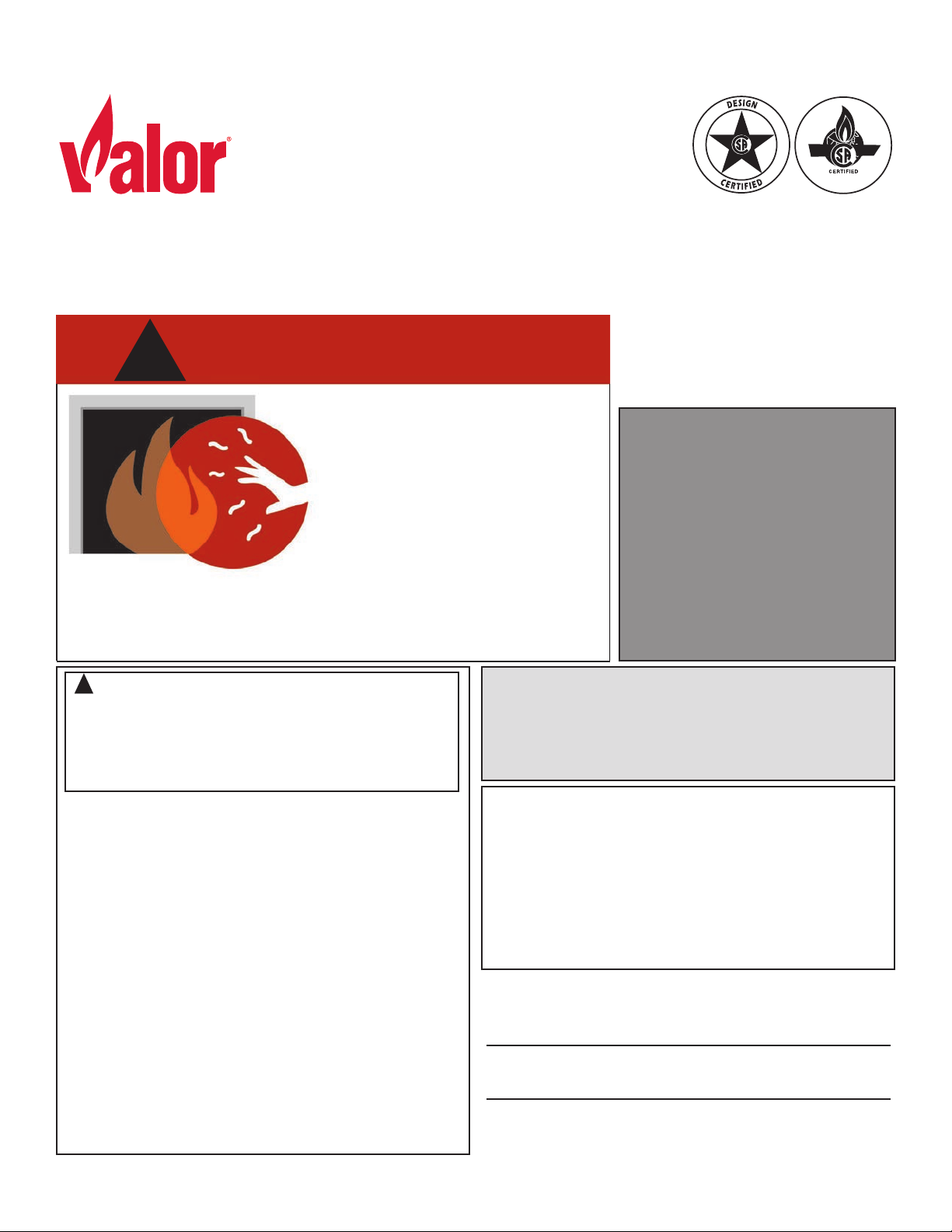
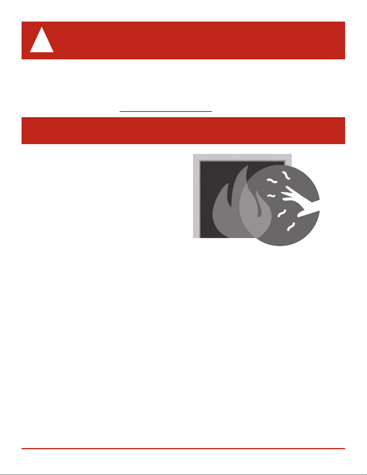
A barrier designed to reduce the risk of burns from the hot
viewing glass is provided with this appliance and shall be
installed for the protection of children and other at-risk
individuals.
! WARNING
FIRE OR EXPLOSION HAZARD
Failure to follow safety warnings exactly
could result in serious injury, death, or
property damage.
— Do not store or use gasoline or other
ammable vapors and liquids in the
vicinity of this or any other appliance.
— WHAT TO DO IF YOU SMELL GAS
▪ Do not try to light any appliance.
▪ Do not touch any electrical switch; do
not use any phone in your building.
▪ Leave the building immediately.
▪ Immediately call your gas supplier from
a neighbor’s phone. Follow the gas
supplier’s instructions.
▪ If you cannot reach your gas supplier,
call the re department.
— Installation and service must be
performed by a qualied installer,
service agency or the gas supplier.
This manual contains instructions to install the
ENGINE ONLY. A trim kit is REQUIRED to
complete the installation. A barrier screen is
provided with the trim kit. Refer to the manual
supplied with the trim for installation.
This appliance may be installed in an after-
market permanently located, manufactured
(mobile) home where not prohibited by local
codes.
This appliance is only for use with the type
of gas indicated on the rating plate. This
appliance is not convertible for use with
other gases, unless a certied kit is used.
This appliance is a domestic room-heating
appliance. It must not be used for any other
purposes such as drying clothes, etc.
This appliance is suitable for installation in
a bedroom or bed sitting room.
Ce guide est disponible en français sur demande.
INSTALLER
Leave this manual
with the appliance.
CONSUMER
Retain this manual
for future reference.
4006013-09
©2019, Miles Industries Ltd.
Table of Contents
FOR THE OWNER FOR THE QUALIFIED INSTALLER
Safety and Your Fireplace ......................................3
Introduction
Locating Fireplace & Lighting Information Card ........6
Operating Your Fireplace for the First Time
.............................................................6
...............6
Operating Y our Fireplace .......................................7
Fireplace Control Devices .........................................7
How to Turn Your Fireplace ON
How to Turn Your Fireplace OFF (and pilot)
How to Ensure Your Fireplace Cannot
Be Turned ON Inadvertently
.................................7
..............7
...................................7
Using the Remote Control .....................................8
Using the Wall Switch
Kits & Accessories
Lighting Instructions
Maintaining Y our Fireplace
Servicing Your Fireplace ..........................................14
Annual Inspection
Cleaning Your Fireplace
Checking Pilot and Burner Flames
Replacing Batteries
Using Handset Wall Holder
..........................................12
...............................................12
............................................13
..................................14
....................................................14
..........................................15
..........................17
.................................................18
......................................18
Warranty ................................................................61
Warranty Card at the back of this manual.
The information contained in this installation manual is
believed to be correct at the time of printing. Miles Industries Ltd. reserves the right to change or modify any
information or specications without notice. Miles Industries Ltd. grants no warranty, implied or stated, for the
installation or maintenance of your heater, and assumes
no responsibility for any consequential damage(s).
Designed and Manufactured by / for
Miles Industries Ltd.
190–2255 Dollarton Highway,
North Vancouver, BC, CANADA V7H 3B1
Tel. 604-984-3496 Fax 604-984-0246
www.valorreplaces.com
2
Specications
.......................................................19
Overview................................................................20
Dimensions & Location
Mantel & Hearth Clearances
Framing Requirements
Venting
...................................................................26
........................................21
................................22
........................................24
Co-axial Venting....................................................27
Co-linear Venting
Installation Planning
Plan Wall Finish .......................................................33
..................................................32
............................................33
Installation .............................................................35
Unpack appliance ....................................................35
Fit Stand-os
Install Heat Shield (side outlet only)
Convert from Side to Top Outlet (if required)
Fit optional LDK HeatShift Duct Kit’s take-o
collars to appliance
Fit the appliance into framing ..................................36
Remove Window
Complete Installation of optional LDK HeatShift
Duct Kit
Set-up Gas Supply ..................................................37
Install Liners
Install Driftwood Kit 2100DWK
Install Decorative Glass Murano 1500DGM
Install Decorative Glass Set 1500DGS
Install Rocks & Shale Set 1514RSS
Install Split Wood Kit 1500SWK ..............................48
Ret Window
Install Remote Battery and Wall Switch Kit
RBWSK (required)
Synchronize Remote Control
Check Operation
Adjust Aeration
Install Trim and Barrier Screen ................................55
Install Remote Control Handset Wall Holder
...........................................................35
........................35
...........36
(if used) ..........................36
.....................................................37
(if used)...........................................37
............................................................39
................................40
............42
....................44
........................46
...........................................................51
................................................52
...................................54
......................................................54
(if necessary) ..........................54
...........55
Wiring Diagram .....................................................56
Approved Venting Components
..........................57
Commonwealth of Massachusetts......................59
Warranty
................................................................61
Spare Parts............................................................62
Massachusetts: The piping and nal
gas connection must be performed by a
licensed plumber or gas tter in the State of
Massachusetts. Also, see Carbon Monoxide
Detector requirements on page 59.
© Copyright Miles Industries Ltd., 2019. All rights reserved.
SAFETY AND YOUR FIREPLACE
!
Safety and Your Fireplace
Read and understand all instructions carefully before
starting the installation. Failure to follow these instal-
lation instructions may result in possible re hazard and
will void the warranty.
Prior to the rst ring of the replace, read the
Owner’s information section of this manual.
Do not use this appliance if any part has been under
water. Immediately, call a qualied service technician
to inspect the unit and to replace any part of the control
system and any gas control that has been under water.
This unit is not for use with solid fuel.
Installation and repair should be performed by a
qualied service person. The appliance and venting
system should be inspected before initial use and at
least annually by a professional service person. More
frequent cleaning may be required due to excessive lint
from carpeting, bedding, etc. It is imperative that the
unit’s control compartment, burner, and circulating air
passageways be kept clean to provide for adequate
combustion and ventilation air.
Always keep the appliance clear and free from
combustible materials, gasoline, and other ammable
vapors and liquids.
Never obstruct the ow of combustion and ventilation air. Keep the front of the appliance clear of all
obstacles and materials for servicing and proper operation.
This unit must be used with a vent system as described in this installation manual. No other vent system or components may be used.
This gas replace and vent assembly must be vented
directly to the outside and must never be attached to
a chimney serving a separate solid fuel burning appliance. Each gas appliance must use a separate vent
system. Common vent systems are prohibited.
Inspect the external vent cap on a regular basis to
make sure that no debris, plants, trees, shrubs are inter-
fering with the air ow.
Turn o the gas before servicing this appliance. It is
recommended that a qualied service technician perform an appliance check-up at the beginning of each
heating season.
WARNING:
This product can potentially expose you to chemicals
including Benzene which are known to the State of
California to cause cancer and birth defects or other
reproductive harm. For more information go to
www.P65Warnings.ca.gov
Do not use this heater as a temporary source of
heat during construction.
Due to the high temperature, the appliance should be
located out of trac areas and away from furniture and
draperies.
Clothing or ammable material should not be placed
on or near the appliance.
This appliance is a domestic room-heating appliance.
It must not be used for any other purposes such as drying clothes, etc.
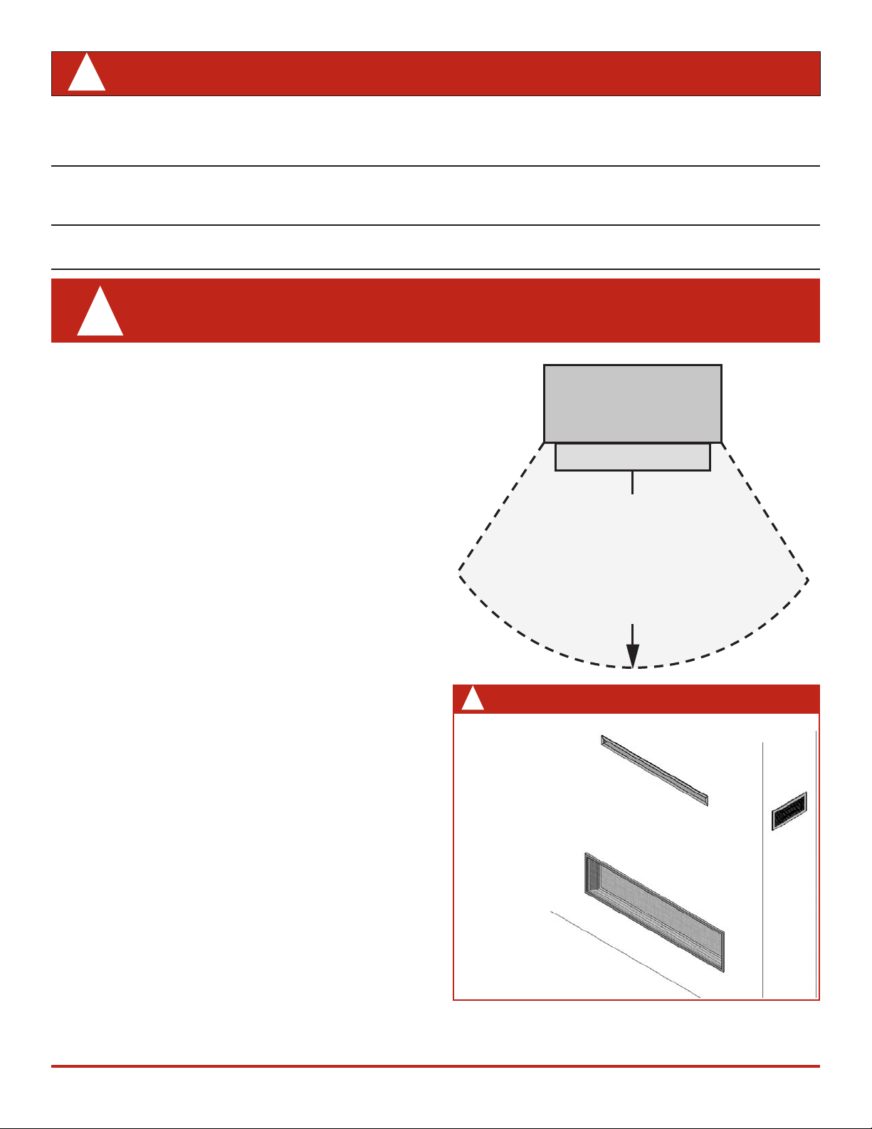
Do not place furniture or any other combustible house-
hold objects within 36” of the replace front.
Be careful not to put any decorating objects sensi-
tive to heat to close above or around the replace as it
gets very hot when operating.
The glass door assembly must be in place and sealed
before the unit can be placed into safe operation.
Do not operate this appliance with the glass door
removed, cracked, or broken. Replacement of the
glass door should be performed by a licensed or qualied
service person. Do not strike or slam the glass door.
The glass door assembly shall only be replaced as
a complete unit, as supplied by the replace manufac-
turer. No substitute material may be used.
Do not use abrasive cleaners on the glass door assem-
bly. Do not attempt to clean the glass door when it is hot.
A barrier designed to reduce the risk of burns from
the hot viewing glass is provided with this appliance and
shall be installed for the protection of children and
other at-risk individuals.
If the barrier becomes damaged, the barrier shall
be replaced with the manufacturer’s barrier for this
appliance.
Any safety screen, guard or barrier removed for
servicing the appliance, must be replaced prior to
operating the appliance.
Children and adults should be alerted to the hazards
of high surface temperature and should stay away to
avoid burns or clothing ignition.
Young children should be carefully supervised
when they are in the same room as the appliance.
Toddlers, young children and others may be susceptible
to accidental contact burns. A physical barrier is
recommended if there are at-risk individuals in the
house. To restrict access to a replace or stove, install
an adjustable safety gate to keep toddlers, young
children and other at-risk individuals out of the room
and away from hot surfaces.
3
WARNING
HOT GLASS WILL
CAUSE BURNS.
DO NOT TOUCH GLASS
UNTIL COOLED.
NEVER ALLOW CHILDREN
TO TOUCH GLASS.
HOT GLASS WILL
CAUSE BURNS.
DO NOT TOUCH GLASS
UNTIL COOLED.
NEVER ALLOW CHILDREN
TO TOUCH GLASS.
WARNING!
!
Safety and Your Fireplace
Read and carefully follow all safety warnings and
operating instructions contained in your owner’s manual
Replacement manuals are available by contacting the Valor Service Department
at 1-800-468-2567 or visit www.valorreplaces.com.
FOLLOW THESE IMPORTANT CHILD SAFETY
PRECAUTIONS AND RECOMMENDATIONS
Parts of your V alor Fireplace become
extremely hot while in operation.
The glass viewing window temperature
can exceed 500 F at full capacity.
Momentary contact with a hot glass
surface can cause a severe burn, even
if the replace is operating at reduced
heating capacity.
The glass window will remain hot
for an extended period of time after
the replace has been turned o.
Ensure that children are prevented from
touching the replace during the cool
down period.
T oddlers and Young Children must
be closely supervised at all times
when they are in the same room as
the operating replace. They lack full
awareness of danger and rely on your
protection. Toddlers, in particular , do
not have the motor skills and response
reexes to withdraw in the event of
accidental contact with a hot surface.
A physical barrier is strongly
recommended if there are young
children, or at-risk individuals in the house.
Install an approved after-market safety
gate to keep toddlers, young children and
other at-risk individuals a safe distance
from the replace.
Keep the remote control handset out
of reach of children at all times. A wall
mount storage holster is provided with
your remote control handset.
Ensure that the replace, including
the pilot light, is completely turned
o when children are present and close
supervision and safety barriers are not
available—see page 7 of this manual.
If the replace is not going to be used
for the summer or any extended period
of time, remove the batteries from the
remote control handset and remote
battery box. It is recommended that
batteries are replaced annually in any
event—see page 18.
4
SAFETY AND YOUR FIREPLACE
!
This manual and particularly the preceeding and following pages contain very important information regarding
the safe operation of your replace as well as maintenance instructions. Read carefully before operating your
replace and pay special attention to the safety warnings.
A heating gas appliance does require safe handling. For this reason, we very strongly recommend children are not
allowed to touch the replace or controls. Install a screen or barrier in front of the replace to protect your children
against severe burns.
This appliance is designed and approved as a supplemental heater and provides the potential for most
energy conservation when used while attended. The use of an alternate primary heat source is advisable.
WARNING
!
• Read the safety information on pages 3 and
4 of this manual before operating your gas
heater.
• Some parts of your replace are extremely
hot, particularly the glass window.
• Do not let children touch the glass or any
parts of your replace even after it is turned
o as it is still hot.
• Use the barrier screen provided with the trim
or a gate to reduce the risk of severe burns.
• Keep the remote control handset out of reach
of children.
• Hot wall surfaces! The wall directly above
the replace is very hot when the replace
heats. It is constructed of non-combustible
materials and although safe, it may reach
temperatures
on choice of trims or optional accessories. DO
NOT TOUCH! We recommend installing the
optional LDK HeatShift Duct Kit when hot
walls are a concern.
• Some materials or items, although safe, may
discolor, shrink, warp, crack, peel, and so on
because of the heat produced by the replace.
Avoid placing candles, paintings, photos, and
other items sensitive to heat within 36 inches
(0.9 m) around the replace.
EXTREMELY HOT!!!
in excess of 200º F depending
Fireplace
Hearth
Do not put
furniture or other objects
in this space in front of
the replace:
36” (0.9 m)
WARNING
!
HeatShift
Duct Kit:
Do not cover
or place items
in front of or
on top of
outlet(s)!
Front outlet
Side
outlet
• Solid wood ooring in front of the replace (if
allowed) may shrink during the heating season
due to heat.
5
OWNER’S
INFORMATION
Introduction
Thank You ...
For purchasing a Valor by Miles Industries. Your new
radiant gas heater is a technical appliance that must
be installed by a qualied dealer. Each Valor replace
is fully tested during the production process for your
safety and comfort.
Your unit has been professionally installed by:
Dealer Name: ________________________________
Phone Number :_______________________________
Should you encounter an operational problem, call
your dealer immediately.
Do not try to repair the unit as you may cause an
injury or damage the replace.
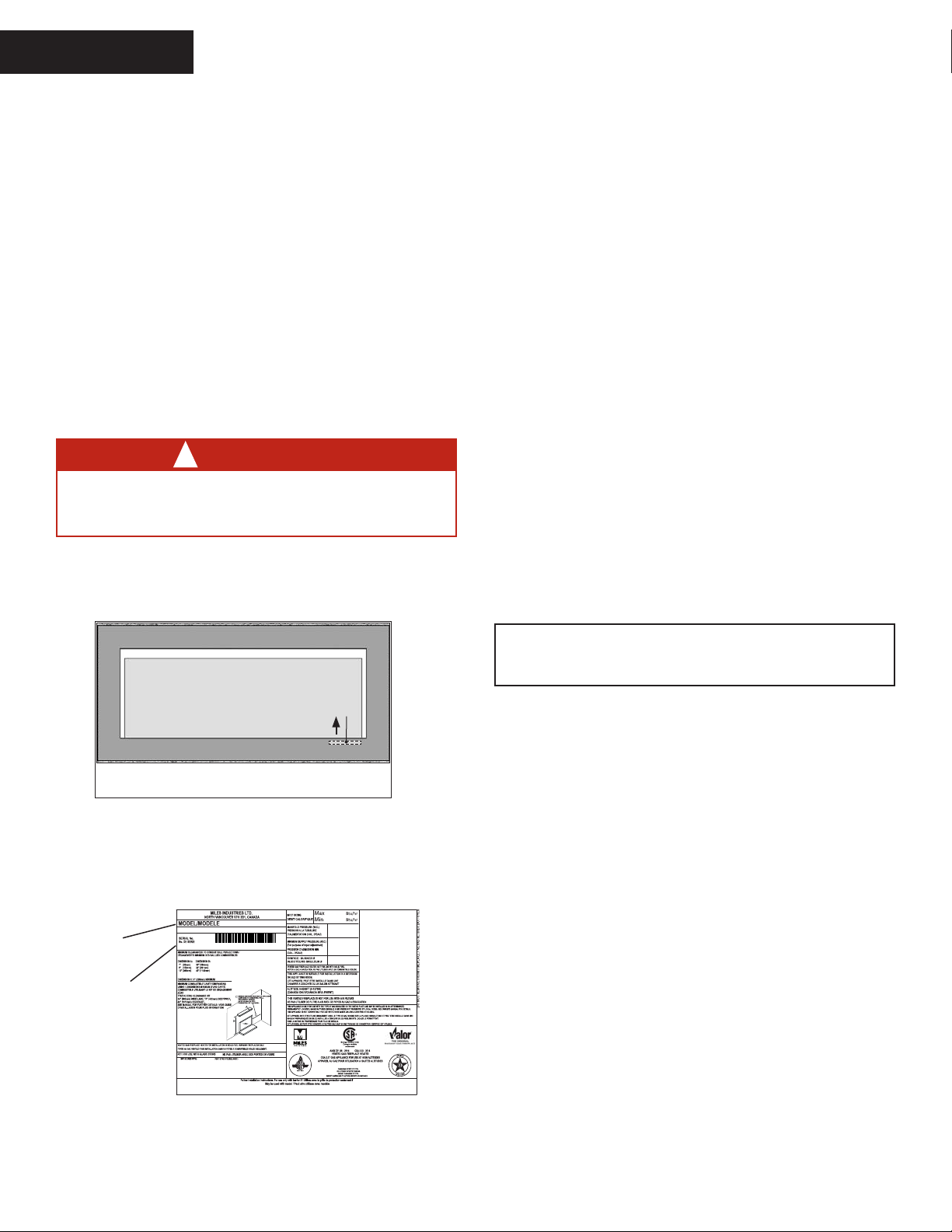
Locating Fireplace & Lighting Information Card
WARNING
!
DO NOT ATTEMPT TO TOUCH THE DATA CARD
WHILE THE FIREPLACE IS STILL HOT! Let the
replace cool rst before touching it.
The Fireplace and Lighting Information card is located at
the right hand side of the replace opening. The card is
attached under the plinth.
Operating Your Fireplace for the First Time
When operating your new replace for the rst time,
some vapors may be released due to the burning of
curing compounds used in the manufacture of the
appliance. They may cause a slight odor and could
cause the ames to be the full height of the rebox, or
even slightly higher, for the rst few hours of operation.
It is also possible that these vapors could set o any
smoke detection alarms in the immediate vicinity.
These vapors are quite normal on new appliances. We
recommend opening a window to vent the room. After
a few hours use, the vapors will have disappeared and
the ames will be at their normal height.
Flame Supervision Device
For your safety, this appliance is tted with a ame
supervision device which will shut-o the gas supply
if, for any reason, the pilot ame goes out. This device
incorporates a xed probe, which senses the heat
from the pilot ame. If the probe is cool, the device will
prevent any gas ow unless manually lighting the pilot.
See full lighting instructions on page 13 of this manual.
Window
The info card is located behind the front
panel below the window.
Info
card
To access the card, remove the barrier screen, side
doors and the plinth. Grab the card and pull it out.
There is important information on both sides of the
card.
24,000
Fireplace
model
Serial
739MN
FOR NATURAL GAS POUR LE GAZ NATUREL
739N 10000
6,500
3.2"
5.0"
750
number
CIRCULATING FAN KIT 755CFK VENTILATEUR POUR CIRCULATION D'AIR 755CFK
120V, 60Hz, LESS THAN 1A 120V, 60Hz, MOINS DE 1A
#4003360-741, #4003293-742, #4003313-745, #4003426-765, #4004666 772
4006176N/01
Performance of propane gas appliances may be
aected by the quality of commercial gas supplied in your area.
6
Operating Your Fireplace
OWNER’S
INFORMATION
Fireplace Control Devices
There are two ways to control your
replace.
1. Thermostatic Remote Control
can be programmed to function
automatically—see pages 8–11;
2. Wall Switch turns re on, o and
Thermostatic
Remote
Control
Wall Switch
controls ame height—see page 12.
How to Turn Your Fireplace ON
Press and hold button(s) until a short beep conrms the
start sequence has begun; release buttons.
Continuing beeps conrm the ignition is in process.
When the pilot is lit, the gas ows—see Using the
Remote Control section for more information.
Alternately, turn o gas supply. In all cases, call your
dealer for service assistance.
ON: parallel to pipe OFF:
perpendicular to
pipe
How to Ensure Your Fireplace Cannot
Be Turned ON Inadvertently
WARNING
!
RISKS OF SEVERE BURNS! SURFACES OF
THE FIREPLACE ARE VERY HOT DURING
OPERATION! Ensure replace has cooled o
before accessing controls.
You can use one of the two following methods to
ensure that your replace will not turn on when you
don’t want it on.
Battery holder
& wall switch
handset
Wall SwitchRemote control
How to T urn Your Fireplace OFF (and pilot)
Press and hold the OFF button for a second (either on
the handset or the wall switch).
handset
If the ames are on, they go down and you hear the
valve motor wind down. You hear a clunk and a beep
indicating that the valve has received the signal from
the remote control.
In the unlikely event that you cannot turn o your
replace with the remote control handset, use the
wall switch; if the wall switch malfunctions and will not
turn o the replace, wait 6 hours and the replace
will automatically go to pilot. You can then access the
controls inside your replace.
Wall SwitchRemote control
Fireplace
Receiver
The receiver and gas valve are located on the bottom of the
replace behind the front panel. The battery holder is located
next to the wall switch.
• On gas valve, turn dial from ON
Gas valve
Gas valve
position to MAN position as
shown. Turning dial to MAN will
ensures that main burner cannot
come on. The pilot will remain on
if lit.
• Alternately, remove all batteries
from the battery holder next to the
wall switch as well as the battery
from the handset.
Automatic Shut-O (in certain
conditions)
Your replace’s remote control is
equipped with an automatic shut-o mechanism which
is activated in certain conditions. See page 12 in the
Using the Remote Control section for a description of
this feature.
7
Remote Control Operation
O
Current
temperature
(F or C)
Current time
(12 or 24 hour clock)
Modes (Manual,
Temperature, Timer)
Handset
sensor
Battery status
Current
programmed
period (Timer)
Period
start or end
(Temp, Timer)
OWNER’S
INFORMATION
Using the Remote Control
Radio Frequency
315 MHz for USA and Canada.
This device complies with Part 15 of the FCC Rules and
with Industry Canada license-exempt RSS standard(s).
Operation is subject to the following two conditions:
(1) this device may not cause harmful interference, and
(2) this device must accept any interference received,
including interference that may cause undesired
operation.
NOTE: Before using the remote control system for
the rst time, the receiver and the handset must
Turn Fireplace ON
Press + buttons until you hear a
short beep; release buttons.
Beeping continues until pilot is lit.
Burner lights to maximum ame height
and handset goes automatically to
manual (MAN) mode.
NOTES:
On the valve, MAN button must be at ON, in full
counter-clockwise position
ON/OFF switch (if equipped) must be in I (ON) position.
be synchronized. See the section Synchronize Remote
Control on page 1.
IMPORTANT: BEFORE YOU BEGIN, please note that on this
system, the settings of time, temperature and automatic
ON/OFF can only be programmed when the function
display is ashing. Be patient when programming as it
can take a few seconds to set.
Note: In the TEMP or TIMER modes, the remote handset
Turn Fireplace OFF
Press button.
When pilot is just turned off , wait 2
minutes to light it again.
Standby Mode (Pilot Flame)
senses the room temperature and adjusts the ame
accordingly.
To communicate, the handset should be within 15�feet
Press and hold to set replace
to pilot.
(4.5 meters) of the replace.
Do not leave the handset on the mantel or hearth.
.
FF (returns to set mode,
turns the burner and
8
SET (scrolls through
modes and settings)
WKHSLORWR
/DUJHȵDPHEXWWRQȵDPHV
up, sets hours, temperature)
6PDOOȵDPHEXWWRQȵDPHV
GRZQDQGRVHWVPLQXWHV
temperature)
Adjust Flames Height
With pilot lit, press and hold buttons:
= increase ame height
= decrease ame height or
set to pilot
For ne adjustment, tap buttons.
Express Low and High Fire
Double-click buttons:
= increase ame to maximum
height “HI”
= decrease ame minimum
height “LO”
NOTE: Flame goes to high re rst
before going to designated low re.
x 2
x 2
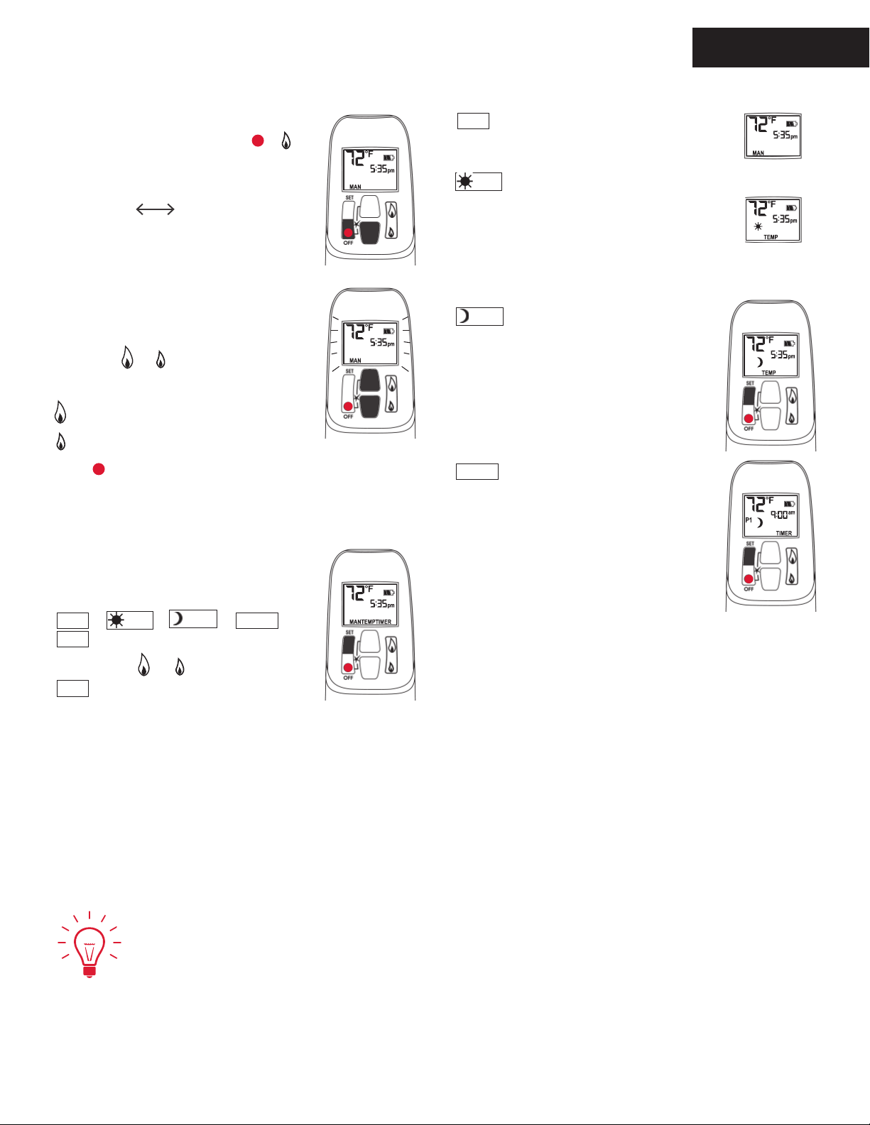
Using the Remote Control
Remote Control Operation
OWNER’S
INFORMATION
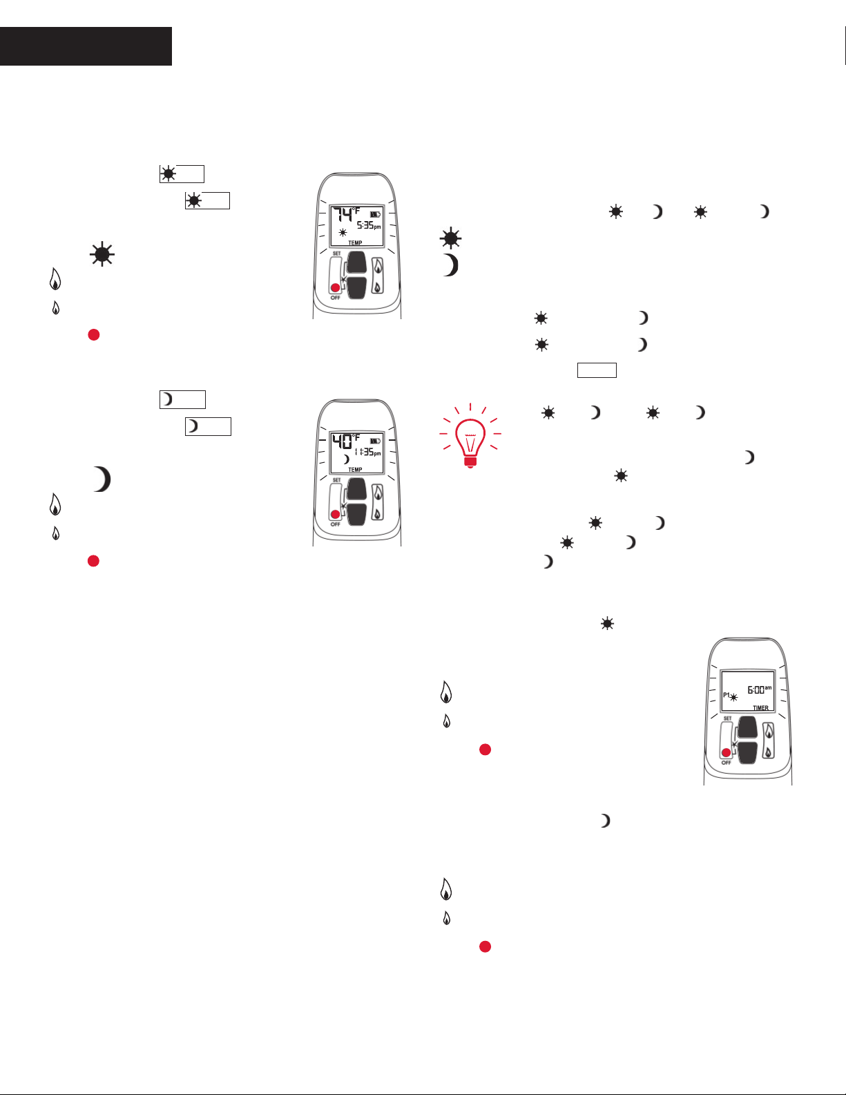
Setting ºC/24-hr or ºF/12-hr clock
In MAN mode, press and hold +
buttons until temperature / clock display
changes from
°F / 12-hour °C / 24-hour
MAN
Manual Mode
Manual ame height adjustment.
TEMP
Daytime Temperature Mode
When pilot is lit, room temperature
is measured and compared to set
temperature. Flame height automatically
adjusts to reach Daytime Set
Temperature.
Setting Time
The time display will ash after either:
- installing the battery, or
- pressing
To set the time, press buttons:
= hour
= minutes
Press
+
or wait to go back to MAN.
Modes of Operation
Brie y pressing SET cycles through
modes of operation.
MAN
MAN
>
TEMP
>
TEMP
>
TIMER
>
TEMP
Night time Setback
Temperature Mode
When pilot is lit, room temperature
is measured and compared to set
temperature. Flame height automatically
adjusts to reach Night Time Setback
Temperature.
TIMER
When pilot is lit, two periods of time (P1
and P2) can be programmed to go ON
and OFF at speci c times.
Note: Display shows set temperature
every 30 seconds.
Timer Mode
NOTE: Press or to reach
MAN
mode.
Set the diff erent parameters when
they are ashing.
9
Remote Control Operation
OWNER’S
INFORMATION
Using the Remote Control
Setting ON / OFF Temperatures
Setting “DAYTIME” temperature.
TEMP
TEMP
TEMP
TEMP
23 °C/ 74 °F
“--” (OFF)
Default Settings:
Press SET to scroll to
Hold SET button until TEMP ashes.
To set Daytime Temperature:
= increases temperature.
= decreases temperature.
Press or wait to complete setting.
Setting “NIGHT TIME SETBACK” temperature.
Default Settings:
Press SET to scroll to
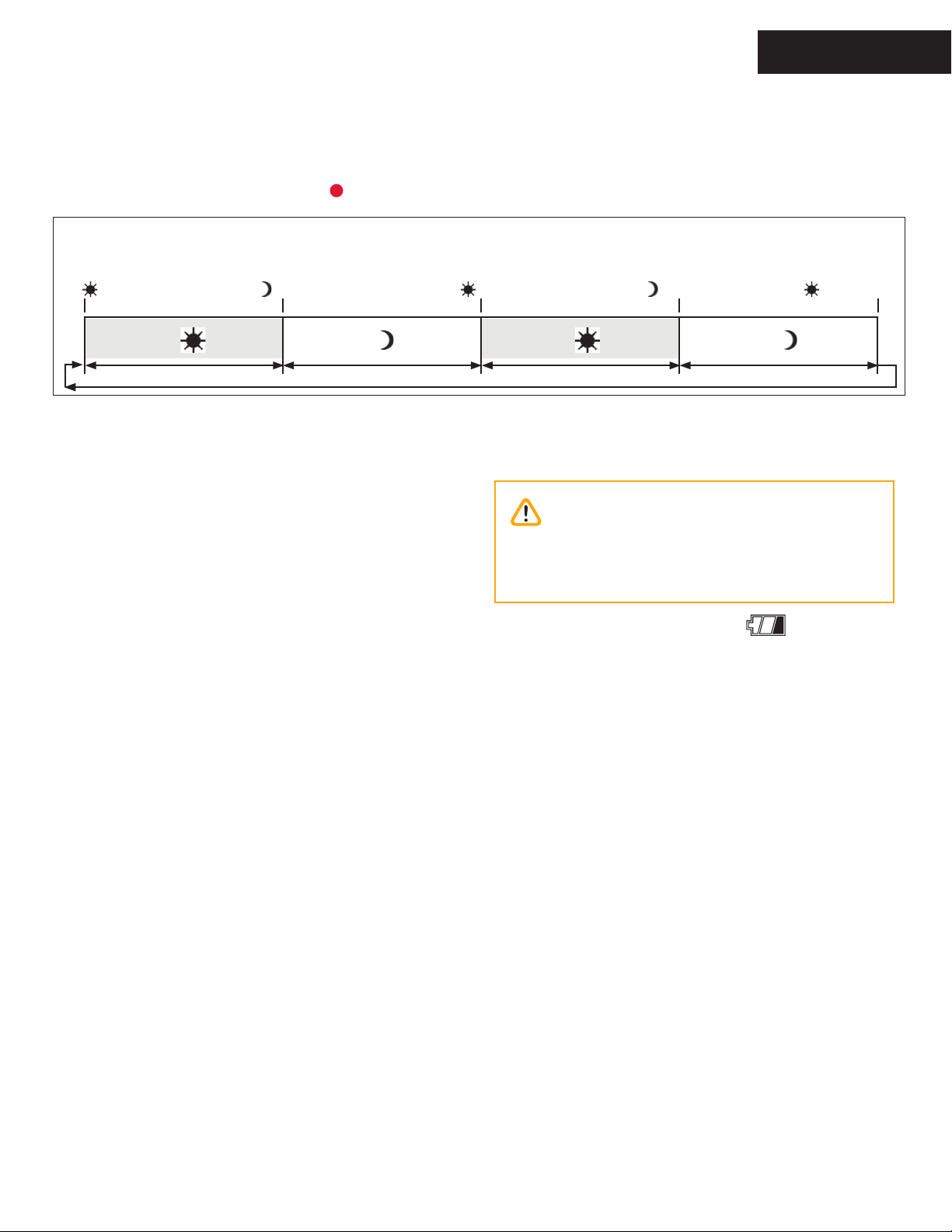
Setting Program Timers
You can program two periods of time between 12 am
and 11:50 pm in each 24-hour cycle.
Programs P1 and P2 must be set in the following order
during a 24-hour cycle:
= beginning of program period, turns ON
= end of program period, turns OFF
Default Settings:
Program 1:
Program 2:
Press SET to scroll to
Hold SET button until TEMP ashes.
To set Night Time Temperature:
= increases temperature.
= decreases temperature.
Press or wait to complete setting.
If
P1
P2
P1
P1
06:00 am
11:50 pm
TIMER
P1
=
or
,
P1
P2
.
P1
08:00 am
11:50 pm
P2
=
,
and
P2
P2
P2
,
programming is cancelled.
To keep replace ON all night, set
11:50 am and
P1
at 12:00 am.
P2
If you want to program only one period,
program
P2
then
P1
as
P1
and
.
P1
and
P2
with desired times
with the same time
.
at
Setting P1 ON time.
Hold SET button until
P1
is displayed and time
ashes.
To set ON time:
= hour
= minutes
Press or wait to complete setting.
Setting P1 OFF time.
Hold SET button until
P1
is displayed
and time ashes.
To set ON time:
= hour
= minutes
Press or wait to complete setting.
10
Using the Remote Control
Remote Control Operation
Setting P2 ON and OFF times.
Repeat same steps as Setting P1 ON and OFF times.
OWNER’S
INFORMATION
When all settings are complete, press
to save them.
Timer Programming Example (default temperatures shown)
6:00 am
P1
Start time
8:00 am
P1
End time
4:00 pm
P2
Start time
Set temp 74F Set temp 40FSet temp 74F
Automatic Turn Down
6 Hour no Motor Movement
Manual Mode/Temperature/Timer Mode: The valve will
turn to pilot ame if there is no change in ame height
for a 6 hour period. In Temperature/Timer Mode if the
ambient room temperature changes, the ame height
will adjust automatically to maintain set temperature,
and the re will continue to function normally. The
valve will turn to pilot ame if the set temperature and
the ambient room temperature remain the same over a
6 hour period.
Automatic Shut-Off
Low Batteries Receiver. With low battery power
in the battery holder the system shuts off the re
completely. This does not apply when the power supply
is interrupted.
On-Demand Pilot. This green feature eliminates
gas energy consumption during extended appliance
inactivity. When the appliance is inactive for 5 days
the system automatically extinguishes the pilot. This
feature helps the consumer realize cost bene ts by
automatically eliminating energy consumption during
non-heating months and limited use.
Set temp 40F
Low Battery Indication
Caution
DO NOT USE a screwdriver or other metallic
object to remove batteries from holder. This
could cause a short-circuit.
Remote handset: The battery icon will show
when the battery needs to be replaced. Replace with
one 9 V alkaline batter y.
Remote battery holder: Frequent ‘beeps’ for 3 seconds
when the valve motor turns indicate the batteries
need to be replaced. Replace with four 1.5 V alkaline
batteries.
Handset / Receiver Match
The remote control handset and receiver are
programmed to function together. In case of a
replacement of the handset or the receiver, you will
need to reset the receiver to allow them to function
together. Contact your dealer for details.
10:00 pm
P2
Start time
6:00 am
P1
Start time
11
OWNER’S
INFORMATION
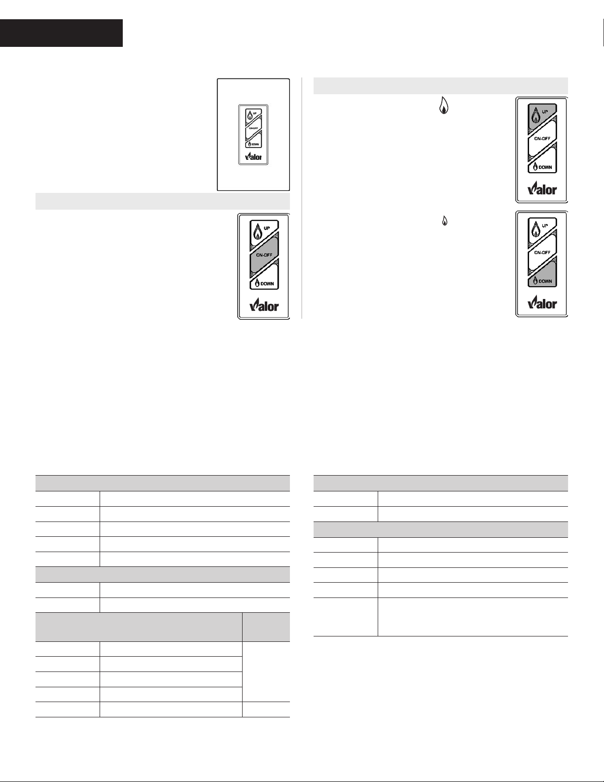
Using the Wall Switch
The Wall Switch can be used to
control your replace. You can
turn the pilot on or o and you can
increase or decrease the ame
height.
Note that the thermostat and
programming functions are not
available with the wall switch.
TO TURN APPLIANCE ON and OFF
Press ON-OFF button once to light
pilot. Press again to shut of pilot.
TO ADJUST FLAME HEIGHT
Press and hold large ame button
to gradually increase ame height.
Press and hold small ame button to
gradually decrease ame height.
Kits & Accessories
Required Kits
Information accurate at the time of printing and subject
to change without notice.
Fuel Beds (choose one)
2100DWK Driftwood Set Kit
1500DGM Decorative Glass Murano
1500DGS Decorative Glass
1514RSS Rock & Shale Set
1500SWK Split Wood Kit
Liners (choose one)
1615FBL Linear Fluted Black Liner Set
1625RGL Reective Glass Panel Kit
Trims (choose one)
1550v2 Linear 3-1/2” Surround
1550LSB Black
1550LSZ Bronze
1550LSP Nickel
1575LFB Linear 1” Finishing Trim Black 4005564
Barrier
Screen
4004215
Optional Accessories
Information accurate at the time of printing and subject
to change without notice.
Conversion Kits
1500NGK Conversion to natural gas
1600PGK Conversion to propane gas
Other Accessories
GV60CKO Outdoor Fireplace Conversion Kit
1506DRK Additional rocks for Driftwood Kit
1270RBK Remote Blower Kit
LDK HeatShift Duct Kits (gravity ow)
Hearth
Gate
Hearth gates such as Cardinal’s
VersaGates are available at retail stores
carrying safety products for children.
12
MISE EN GARDE : Quiconque ne respecte pas à la lettre les instructions dans la présente
A.
B.
Cet appareil possède une veilleuse qui doit être allumée par télécommande ou à la main. Suivez ces instructions à la
lettre. Pour économiser l’énergie, éteignez la veilleuse lorsque vous n’utilisez pas l’appareil.
AVANT DE FAIRE FONCTIONNER, sentez tout autour de l’appareil pour déceler une odeur de gaz. Sentez près du
plancher, car certains gaz sont plus lourds que l’air et peuvent s’accumuler au niveau du sol.
QUE FAIRE SI VOUS SENTEZ UNE ODEUR DE GAZ :
• Ne pas tenter d’allumer d’appareil.
• Ne touchez à aucun interrupteur; ne pas vous servir des téléphones se trouvant dans l’édifice.
• Appelez immédiatement votre fournisseur de gaz depuis un voisin. Suivez les instructions du fournisseur.
• Si vous ne pouvez joindre le fournisseur, appelez le service des incendies.
C. Ne poussez ou ne tournez le bouton d’admission du gaz qu’à la main; ne jamais utiliser d’outil. Si le bouton reste
coincé, ne pas tenter de le réparer; appelez un technicien qualifié. Le fait de forcer le bouton ou de le réparer peut
déclencher une explosion ou un incendie.
D. N’utilisez pas cet appareil s’il a été plongé dans l’eau, même partiellement. Faites inspecter l’appareil par un techn-
-icien qualifié et remplacez toute partie du système de contrôle et toute commande qui ont été plongés dans l’eau.
COMMENT COUPER L’ADMISSION DE GAZ DE L’APPAREIL
2. POUR ARRÊTER L’ENTRÉE DE GAZ, éteignez la soupape en pressant sur le bouton OFF
(point rouge) sur la manette de télécommande (1).
•
plancher s’il y a une odeur de gaz. Si c’est le cas, ARRETEZ!
Attendez cinq (5) minutes pour laisser
sécurité ci-dessus. S’il n’y a pas d’odeur de gaz, passez à l’étape suivante.
• Sur la télécommande, appuyez en même temps sur les boutons OFF (●) et grande
flamme ( ); un court signal sonore indiquera le début de proceédê d’allumage;
• De courts signaux sonores seront entendus jusqu’à ce que le procédé d’allumage
soit complet et que le gaz ait circulé dans les tuyaux jusqu’à la soupape;
•
automatiquement au réglage le plus haut;
•
•
• À l’aide d’un objet pointu comme un stylo, appuyez sur le centre métallique (4) pour
établir l’arrivée du gaz à la veilleuse;
•Toujours en appuyant sur le centre métallique (4), allumez le gaz à la veilleuse (5) avec une allumette:
• Continuez d’appuyer sur le centre métallique (4) pour à peu près 10 secondes; relâchez
repérez la veilleuse (fig 3) dans la boite de foyer.
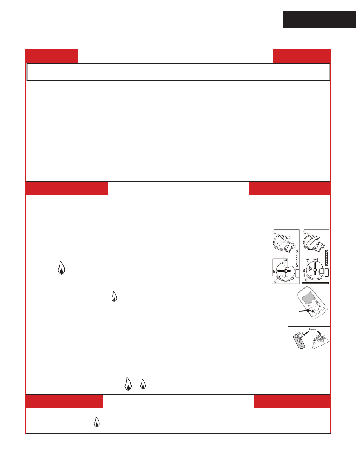
• Si la veilleuse s’allume mais ne reste pas allumée après plusieurs essais, tournez le bouton d’alimentation de gaz
(3) à la position “OFF” ( ) et appelez votre agent de service ou votre fournisseur de gaz.
•
le haut ( ) ou le bas ( ) ou utilisez les boutons des flammes ( ) ( ) sur la
1. ARRÊTEZ ! Lisez les instructions de sécurité ci-dessus.
3. ALLUMAGE AUTOMATIQUE
4. ALLUMAGE MANUEL
des flammes (3) est au r
Lorsque la veilleuse s’allumera, la bouton d’ajustement des flammes (3) tournera
Appuyez sur le bouton petite flamme ( ) pour réduire la hauteur des flammes.
Réglez le bouton de règlage de flammes (3) â la température la plus basse ( );
Replacez la fen
1. ARRÊT AUTOMATIQUE (à l’aide de la télécommande) :
Appuyez et maintenez le bouton petite flamme ( ) pour arrêter l’alimentation de gaz au brûleur;
•
notice risque de déclencher un incendie ou une explosion entraînant des dommages, des
blessures ou la mort.
OWNER’S
Lighting Instructions
INFORMATION
FOR YOUR SAFETY, READ BEFORE LIGHTING
WARNING: If you do not follow these instructions exactly, a fire or explosion may result
causing property damage, personal injury or loss of life.
A. This appliance has a pilot which must be lighted by hand or by remote control. Follow these instructions exactly. To
save gas, turn the pilot off when not using the appliance for a prolonged period of time.
B. BEFORE LIGHTING, smell all around the appliance area for gas. Be sure to smell next to the floor because some gas
are heavier than air and will settle on the floor.
WHATTO DO IF YOU SMELL GAS
• Do not try to light any appliance.
• Do not touch any electric switch; do not use any phone in your building.
• Immediately call your gas supplier from a neighbor’s phone. Follow the gas supplier’s instructions.
• If you cannot reach your gas supplier, call the fire department.
C. Use only your hand to push in or turn the control knobs. Never use tools. If the knobs will not push in or turn by hand,
don’t try to repair them; call a qualified service technician. Force or attempted repair may result in a fire or explosion.
D. Do not use this appliance if any part has been under water. Immediately call a qualified service technician to inspect
the appliance and to replace any part of the control system and any gas control, which has been under water.
LIGHTING INSTRUCTIONS
1. STOP! Read the safety information above.
2. TO CLEAR ANY GAS, turn main valve off by pressing OFF (red dot) button on remote
Wait five (5) minutes to clear out any gas, then smell for gas, including near the floor. If you smell gas, STOP! Follow
•
“B” in the safety information above on this label. If you don’t smell gas, go to the next step.
3. AUTOMATIC IGNITION: MAN-knob (2) in ON position. Ensure Flame Adjustment
knob (3) is set to lowest setting ( ) (Fig. 1). Locate the pilot (Fig. 3.) inside of firebox.
• ON/OFF wall switch (1) in ON position,
On the remote control handset, press the OFF button (red dot) and large flame
•
button ( ) simultaneously; a short acoustic signal confirms the start has begun.
• Further short acoustic signals indicate the ignition process is in progress.
• When the pilot is lit, the Flame Adjustment knob (3) will automatically rotate to the highest setting
• Press the small flame button ( ) on the remote control handset to reduce the flame height
4. MANUAL IGNITION: MAN-knob (2) in MAN position (Fig. 2). With the window off,
locate the pilot (fig. 3) inside of the firebox.
• Set Flame Adjustment knob (3) to the lowest setting ( ).
• Push down the metallic core (4) with a pen or similar instrument; this will establish the pilot gas flow.
• Light gas at the pilot (5) with a match.
• Continue holding down metal core (4) for about 10 seconds; after release, pilot should remain lit.
• If the pilot will not stay lit after several tries, turn the gas control knob (3) to OFF ( ) and call your local
service technician or gas supplier.
• Reinstall the window and set the MAN-knob (2) to ON; turn Flame
manually or use the flame buttons ( ) ( ) buttons on the remote control handset to adjust the flame height.
Adjustment knob (3) up ( ) or down ( )
handset (1).
Fig 1
1
OFF
5
Fig 3
TO TURN OFF GAS TO APPLIANCE
1. AUTOMATIC SHUT-OFF (using the remote control handset):
Press and hold the (small flame) on the remote control handset to shut-off the main burner gas flow;
•
Press “OFF” button (red dot) on remote handset to shut-off the appliance, including pilot flame.
•
Fig 2
13
OWNER’S
INFORMATION
Maintaining Your Fireplace
Servicing Your Fireplace
We recommend having your replace serviced every year. Contact your supplier quoting the model
number. It will be helpful if the appliance’s serial number can also be quoted. These numbers are
on the information card. The replacement parts are shown at the end of this manual. Please always
quote the part number and description when requesting spare parts.
Annual Inspection
In order to maintain the safe operation of your replace, contact your dealer to have a qualied
technician go over the list below and make the necessary verications at least once every year.
Safe Operation List
To be performed by a qualied technician only
1. Inspect and operate the pressure relief mechanism to verify relief mechanisms are free from
obstruction to operate. See Cleaning Your Fireplace: To ret the window section of this manual.
2. Clean glass window with a suitable replace glass cleaner. Abrasive cleaners must not be used.
Be careful not to scratch the glass when cleaning. See Cleaning Your Fireplace section of this manual.
3. Inspect the operation of the ame safety system Pilot or Flame rectication device.
4. Inspect and ensure the lighting of the main burner occurs within 4 seconds of the main gas valve
opening. Visual inspection should match that outlined in the appliance instruction manual. Inspect
primary air openings for blockage. See Checking Pilot and Burner Flame section of this manual.
5. Inspect condition of vent and vent terminal for sooting or obstruction and correct if present.
6. Vacuum and clean any debris in the rebox that is not supposed to be there.
7. Test and measure the ame failure response time of the ame safety system.
It must de-energize the safety shuto in no more than 30 seconds.
8. Check all accessible gas-carrying tubes, connections, pipes and other components for leaks.
See Set up Gas Supply section of this manual.
14
Maintaining Your Fireplace
OWNER’S
INFORMATION
Cleaning Your Fireplace
WARNING
!
DO NOT TOUCH THE GLASS WHILE IT IS HOT!
Let the replace cool rst before cleaning it.
Important - Glass cleaning - Mineral deposits
One of the by-products of the combustion process in
a gas appliance is a mineral which can show up as a
white lm on the ceramic glass of the viewing door.
The composition of the deposit varies with location and
time. It is believed to be associated with the varying
sulfur content of the gas. You may have the problem
intermittently.
We have consulted with ceramic glass manufacturers
and they cannot oer a denitive solution to this problem. Dealers have tried various cleaning products with
varying results. The following are recommendations
only and are not meant to guarantee results.
NOTE: This is a problem beyond Miles Industries’
control and is not covered under warranty.
• Clean the glass regularly as soon as you notice
the buildup (white lm). If the lm is left for a longer
period of time, it will etch into the glass. It is then
much harder, if not impossible, to remove.
• NEVER use an abrasive cleaner or ammonia-
based cleaner on the ceramic glass. Any
abrasion of the surface has the immediate eect of
compromising the strength of the glass. An emulsion
type cleaner is recommended.
• Use a soft damp cloth to apply the cleaner. Dry the
glass with a soft, dry, preferably cotton cloth. Most
paper towels and synthetic materials are abrasive to
ceramic glass and should be avoided.
• Our dealers have had good results from the
products listed below. We cannot, however,
guarantee the results of these products.
◊ Brasso, Polish Plus by Kelkem, Cook Top Clean
Creme by Elco, White O by Rutland, Turtle Wax
Do not clean the glass while it is hot!
Always securely replace the window and the barrier
screen before lighting.
If broken, the glass pane may only be replaced
as a complete window unit as supplied by the
manufacturer.
Clean the window panes following the guidelines in this
section.
Clean the steel trim with mild soap and warm water.
Any alcohol/solvent base cleaner will weaken the coat-
ing and damage it.
Clean the barrier screen dusting it with a soft brush.
Clean the rebox ceramic logs/rocks and walls dusting
them with a soft brush. Dust can also be removed from
the burner using a soft brush after removing the fuel
bed. When cleaning, make sure that no particles are
brushed into the slots of the burner.
WARNING
!
CHOKING HAZARD! Ensure that the replace
area is clear of rebed particles as these could
be ingested by small children. Vacuum thoroughly
around the replace area after cleaning.
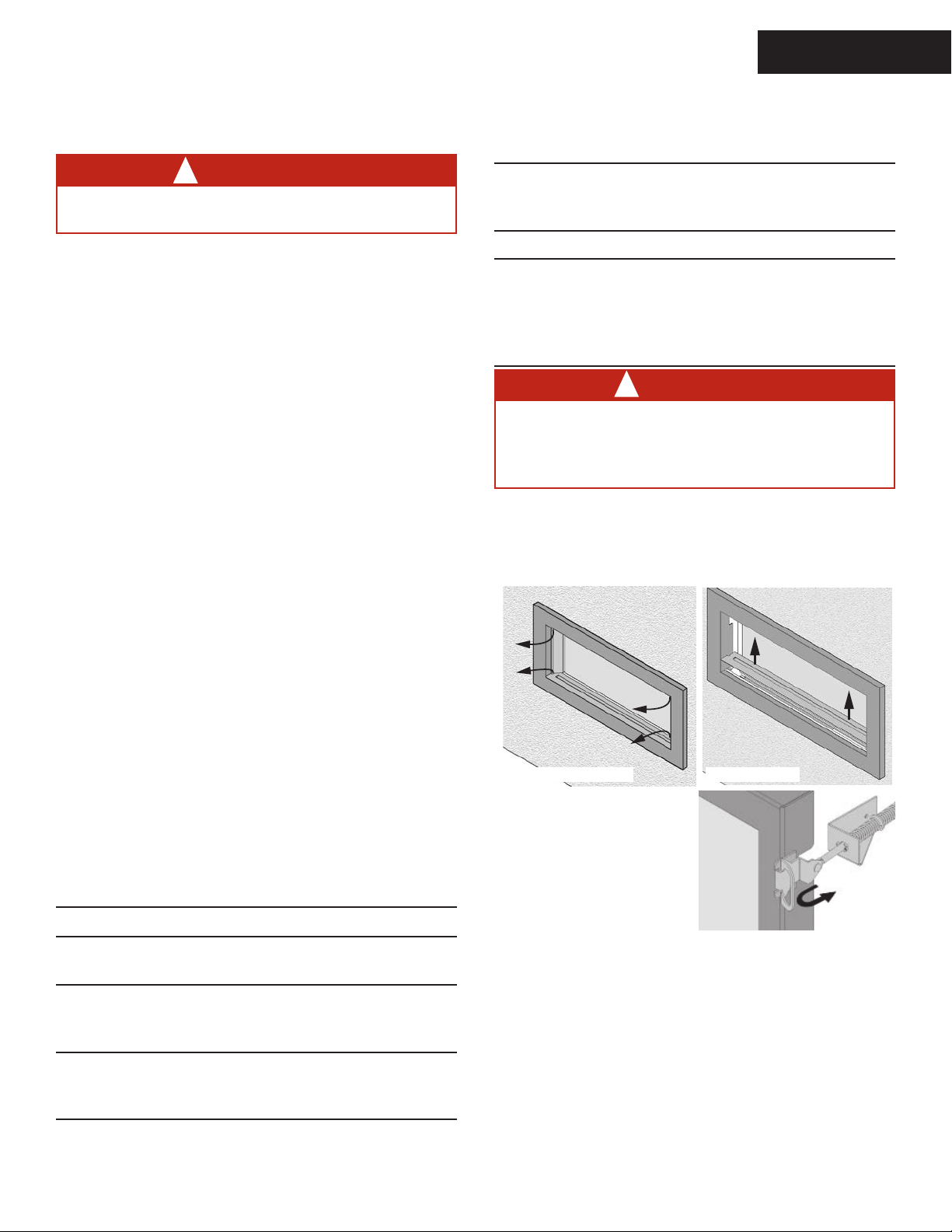
To remove the window for cleaning:
1. Remove the barrier screen.
2. Remove the side doors and the plinth.
Remove plinthRemove side doors
3. Find the levers on each
side of the window
towards the top. Using
your nger, pull the
levers towards you and
unhook them from the
window frame brackets.
4. Gently pull the top of
the window outward.
5. Lift the window out of its bottom railing and set it
aside in a safe place to avoid damage.
Spring Loaded
Window Levers
If the barrier becomes damaged, the barrier shall
be replaced with the manufacturer’s barrier for this
appliance.
15
OWNER’S
INFORMATION
Maintaining Your Fireplace
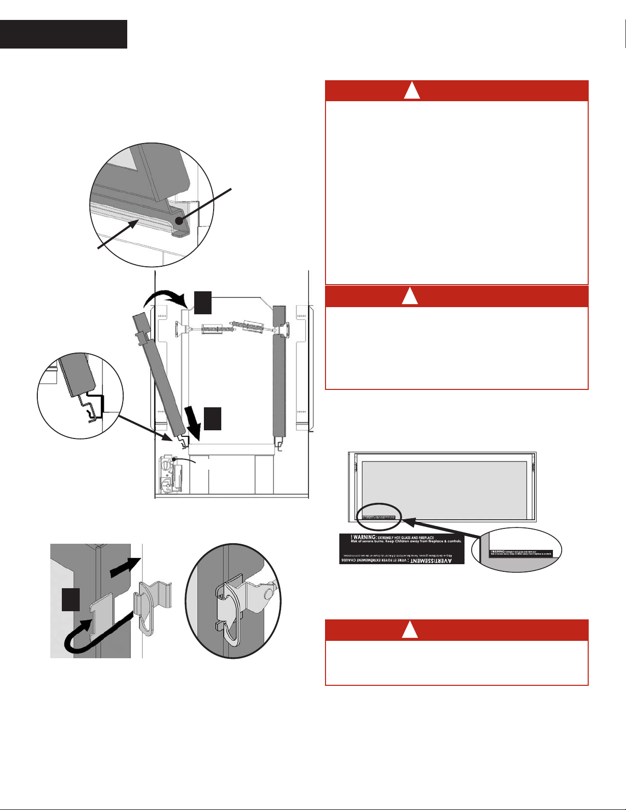
To ret the window:
1. Place the window in its bottom railing. Ensure to
remove any vermiculite or glass particles in
the railing before installing the window.
Window frame
Bottom railing
2. Push the top
of the window
frame against
the rebox.
Section Views
2
1
Valve
DANGER
!
The window unit must be correctly installed,
fastened and sealed after servicing or serious
bodily injury and/or damage to the appliance
may result.
To ensure a safe operation:
• Double-check that the bottom of the window
frame is correctly installed in the bottom
support railing;
• Verify that the levers are hooked properly to
the window tabs then;
• Pull out the top of the window and release it
to insure the springs return it;
• Ensure the window is sealed before operation.
WARNING
!
Failure to install the window correctly can
leak carbon monoxide, aect the performance
of the replace, damage components, cause
overheating resulting in dangerous conditions.
Damage caused by incorrect window installation is not covered by the Valor warranty.
5. If the Hot Glass Warning plate has been removed
from the front lower corner of the window,
reinstall it by sliding it between the glass and
the frame as indicated.
3. While you hold it, pull the side levers back into the
window brackets on each side.
3
4. Apply rm hand pressure around the window frame to
ensure the window is sealed tight against the rebox.
16
Hot Glass Warning Plate
6. Reinstall the plinth and side doors.
7. Reinstall the barrier screen on the trim.
WARNING
!
FOR SAFETY PURPOSE, ensure the barrier
screen is re-installed on the fireplace after
maintenance.
8. Verify that the screen is properly hooked to the trim
and secure.
Maintaining Your Fireplace
OWNER’S
INFORMATION
Checking Pilot and Burner Flames
A periodic check of the pilot and burner ames should
be made. Check after the re has been on for at least
30 minutes. The pilot ame must cover the tip of the
thermocouple probe. The main burner ame pattern will
vary from appliance to appliance depending on the type
of installation and climatic conditions.
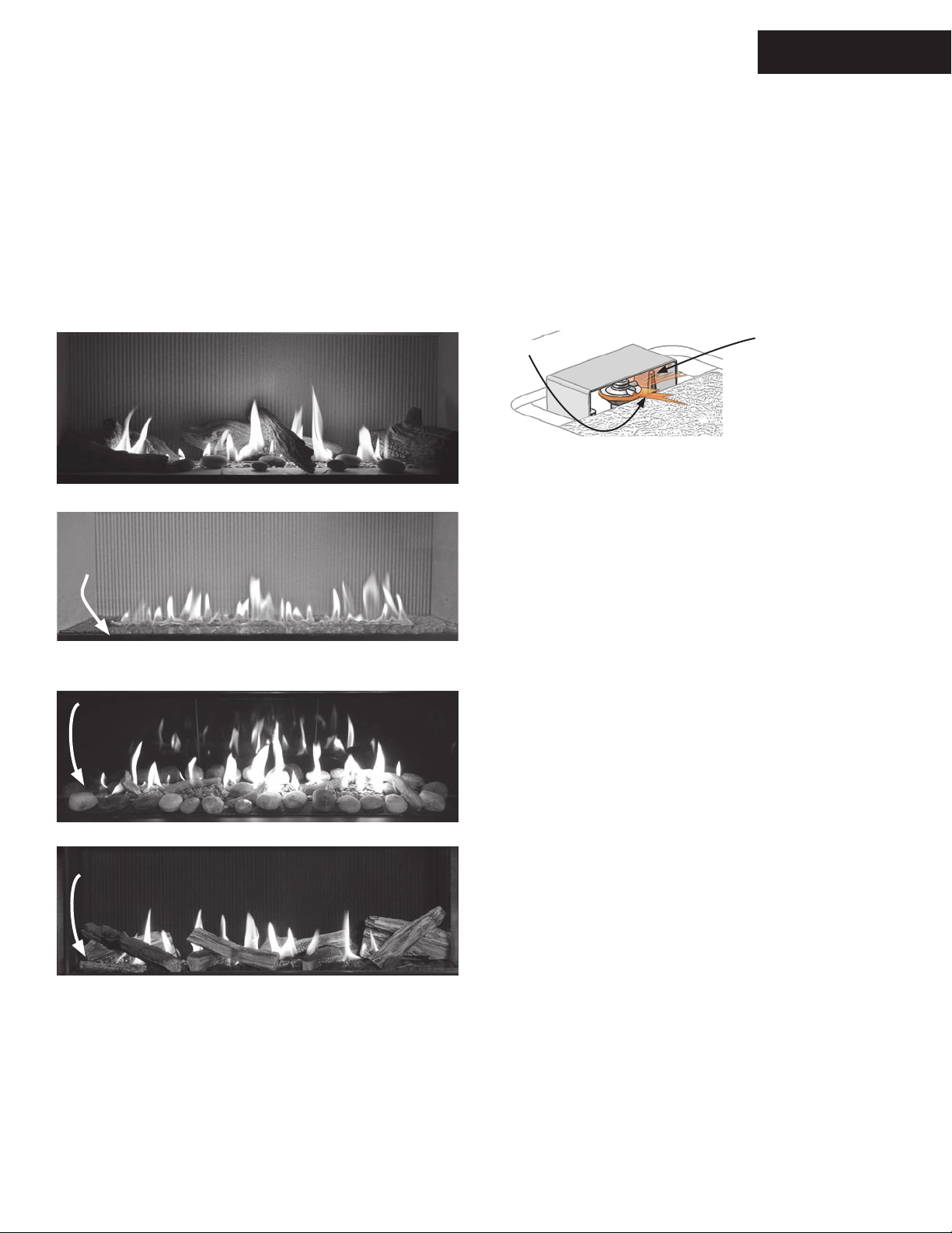
Correct Flame Appearance
Pilot Flame can be seen
between the front and
rear left logs
1505DWK—Long Beach Driftwood
Pilot Flame can
be seen left of
the re bed
The appliance area must always be kept clear and
free from combustible materials, gasoline and other
ammable vapors and liquids.
Inspect the vent terminal outdoors regularly to make
sure that snow, trees, bushes, leaves, or other objects
do not obstruct it.
Examine the vent system and terminal regularly. We
recommend annually.
Pilot Flame
Thermocouple Probe
must be in Flame
1500DGM—Decorative Glass Murano
1500DGS—Decorative Glass
Pilot Flame can
be seen left of
the re bed
1514RSS—Rock & Shale
Pilot Flame can
be seen left of
the re bed
1500SWK—Split Wood
17
OWNER’S
INFORMATION
Maintaining Your Fireplace
Replacing Batteries
WARNING
!
DO NOT ATTEMPT TO CHANGE THE BATTERIES WHILE THE FIREPLACE IS STILL HOT! Let
the replace cool rst before touching it.
CAUTION
DO NOT USE a screwdriver or other metallic object
to remove the batteries from the battery holder or
the handset! This could cause a short circuit.
Low batteries signal: see page 11.
BEFORE changing the batteries, turn the replace
o (including pilot).
The appliance uses four 1.5 V AA alkaline batteries
located next to the wall switch and one 9 V alkaline
battery in its handset. Batteries should last one to two
seasons, depending on usage. Removing the batteries
in the o-season will extend the battery life.
To replace the batteries:
The battery compartment is located next to the wall
switch in the vicinity of the replace. Its front plate is
attached with magnets to the wall switch box.
Battery holder
& wall switch
1. Pull on the plate next to the wall switch to access
the batteries.
2. Disconnect the snap connector from the battery
holder. Do not pull the connector by the wire!
Disconnect
connector
3. Replace the batteries with 4 AA alkaline batteries
orienting them as indicated inside the holder.
4. Reconnect the snap connector to the battery holder.
5. Put the battery holder back in its place beside the
wall switch and snap it in place.
Fireplace
The battery holder is located beside the wall switch.
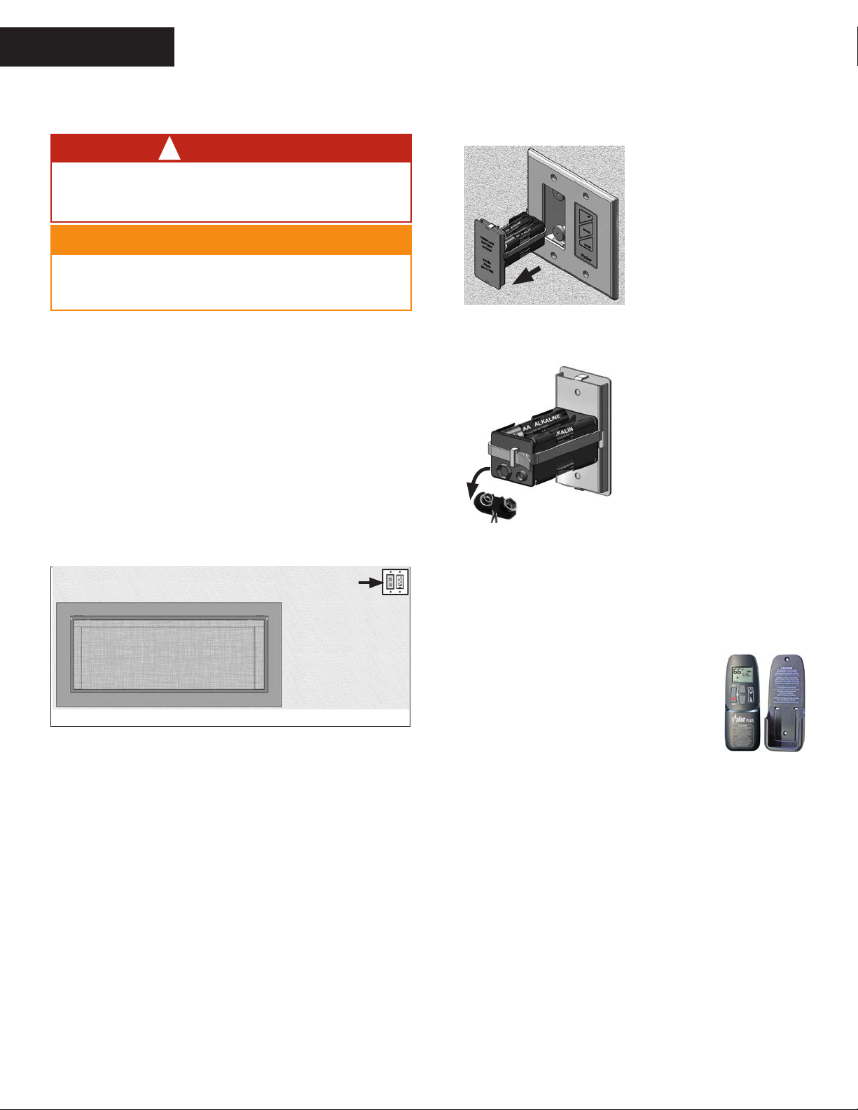
Using Handset Wall Holder
Your replace equipment includes a wall
holder to store the handset. If it hasn’t be
installed, refer to the instructions further
on in this manual for the installation.
18
Specications
QUALIFIED
INSTALLER
Approval & Codes
This appliance is certied to ANSI Z21.88-2016/CSA
2.33-2016 American National Standard / CSA Standard
for Vented Gas Fireplace Heaters for use in Canada
and USA, and to CGA 2.17-91 High Altitude Standard in
Canada. This appliance is for direct vent installations.
This appliance complies with CSA P.4.1-15 Testing
method for measuring annual replace eciencies.
The installation must conform to local codes or, in the
absence of local codes, with the National Fuel Gas Code,
ANSI Z223.1/NFPA 54 or the Natural Gas and Propane
Installation Code CAN/CGA-B149.1. Only qualied
licensed or trained personnel should install this appliance.
This appliance must be electrically grounded in
accordance with local codes, or, in the absence of local
codes, with the National Electrical Code, ANSI/NFPA
70 or the Canadian Electrical Code, CSA C22.1.
Ratings
Model JN JP
Gas Natural Propane
Altitude (Ft.)* 0-4,500 feet*
Input Maximum (Btu/h) 30,000 26,000
Input Minimum (Btu/h) 18,000 18,500
Manifold Pressure (in w.c.) 4.0” 10.0”
Minimum Supply Pressure (in
w.c.)
Maximum Supply Pressure (in
w.c.)
Main Burner Injector Marking 850 260
Pilot Injector Marking 51 30
Min. Rate By-Pass Screw 220 160
5” 11”
10” 14”
*High Altitude Installations
Input ratings are shown in BTU per hour and are
certied without deration for elevations up to 4,500 feet
(1,370 m) above sea level.
For elevations above 4,500 feet (1,370 m) in USA,
installations must be in accordance with the current
ANSI Z223.1 and/or local codes having jurisdiction.
Heating value of gas in some areas is reduced to
compensate for elevation—consult your local gas utility
to conrm.
For installations at elevations above 4,500 feet
(1,370 m) in Canada, please consult provincial and/or
local authorities having jurisdiction.
The supply connection
is 3/8” NPT male and
located on the left hand
side of the rebox.
A shut-o valve (not
supplied) is required
on the supply line to
isolate the unit during
service. See Gas Supply
Installation section for details.
X
Valve access side
Conversion Kits
The 1600J L1 Two-Sided is supplied as natural gas or
propane gas and is eld convertible between fuels. See
instructions packaged with the conversion kit for further
information.
Electrical
The 1600J is designed to run on battery power and
does not require an electrical power source to operate
as a heater. However, it requires electrical power to
operate optional 1270RBK Remote Blower Kit.
LDK HeatShift Duct Kit
The 1600J is designed to allow the installation of the
optional LDK HeatShift Duct Kit, a convection system
that redistributes the warm air ow away from the
replace opening to a more desirable location using
natural convection, without use of a fan.
The warm air ow may be relocated to a position higher
up the wall, out the sidewalls, or even to another room.
The result is much cooler wall temperatures above the
replace opening for locating televisions, artwork, etc.
Please note that the framing and mantel clearances
are aected by the installation of the LDK. Refer
to the installation manual packed with the kit for more
information.
Outdoor Conversion Kit
The 1600J models are supplied standard for indoor
applications and may be adapted for installation in
specic “outdoor” applications protected from weather as
dened in the GV60CKO outdoor conversion kit manual.
WARNING
!
Optional electrical accessories
ARE NOT ALLOWED when adapting
appliance for outdoor use.
Supply Gas
Heater engine 1600JN is used with natural gas.
Heater engine 1600JP is used with propane gas.
The supply pressure must be between the limits shown
in the Ratings section above.
This appliance is designed and approved as a
supplemental heater and provides the potential
for most energy conservation when used while
attended. The use of an alternate primary heat
source is advisable.
19
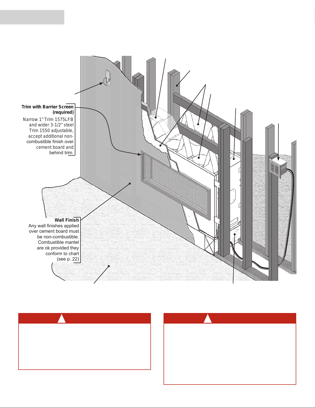
Wall Finish
Any wall nishes applied
over cement board must
be non-combustible.
Combustible mantel
are ok provided they
conform to chart
(see p. 22)
Trim with Barrier Screen
(required)
Narrow 1” Trim 1575LFB
and wider 3-1/2” steel
Trim 1550 adjustable,
accept additional non-
combustible nish over
cement board and
behind trim.
QUALIFIED
INSTALLER
Remote Handset
Wall Holder
Overview
Note: This appliance may be installed in outdoor, weather protected environments
as dened in the GV60CKO Outdoor Conversion Kit instruction manual.
Supplied as horizontal side outlet, eld
convertible to top vertical outlet.
Framing—See Framing Requirements
1/2 inch thick non-combustible
cement board – NOT supplied
Optional LDK HeatShift Duct Kit outlets (4)
Remote Battery
1600J heater
and Wall Switch
Kit (required)
(35-foot wire
length) (supplied)
Some materials or items, although safe,
may discolor, shrink, warp, crack, peel, and
so on because of the heat produced by the
replace. Avoid placing candles, paintings,
photos, and other items sensitive to heat
around the replace.
20
Combustible Floor
WARNING
!
Combustible Framing Allowed Beneath Fireplace. When
the appliance is installed directly on carpeting, tile or other
combustible material other than wood ooring, the appliance
shall be installed on a metal or wood panel extending the full
width and recessed depth of the appliance.
WARNING
!
HOT WALL SURFACES! The wall directly
above the replace is constructed of non-
combustible materials and, although safe, it
may reach temperatures in excess of 250° F
depending on choice of trims. Do not touch.
Finish the wall using materials suitable
for these temperatures. We recommend
installing optional LDK HeatShift Duct Kit
when hot walls are a concern.

Remote Blower
Dimensions & Location
QUALIFIED
INSTALLER
Dimensions
18-1/2”
(470 mm)
9-1/4”
(235 mm)
Center
of vent
6-5/8” dia.
Venting eldconvertible from
side to top outlet
5-1/2”
(140 mm)
Center
Line
(76 mm)
Heat shield
required for
side vent
outlet
applications
33-1/8” (841 mm)
3”
14-1/2”
Center of vent
1-3/8”
(35 mm)
Valve access side
(369 mm)
51-1/4” (1302 mm)
45-1/4” (1050 mm)
Zero Clearance
Stand-Os
Zero Clearance
Stand-Os
Optional LDK HeatShift
Duct Kit outlets
18-1/2”
(470 mm)
Min. 43” (1093 mm)
to top of cement board
Min. 44-1/2” (1130 mm)
Header
to underside of header
32-9/16” (828 mm)
Gas Line
Access Point
Location
2-3/4”
(70 mm)
9-3/8”
(238 mm)
Room Divider
39-11/16” (1009 mm)
Front ViewLeft Side View Right Side View
(Valve access side)
(other side same dims)
Peninsula
Island
X
Optional
1270RBK
NOT for
exterior
wall
installation
21
 Loading...