

Valor 1440 Installation Instructions Manual
H6 SERIES
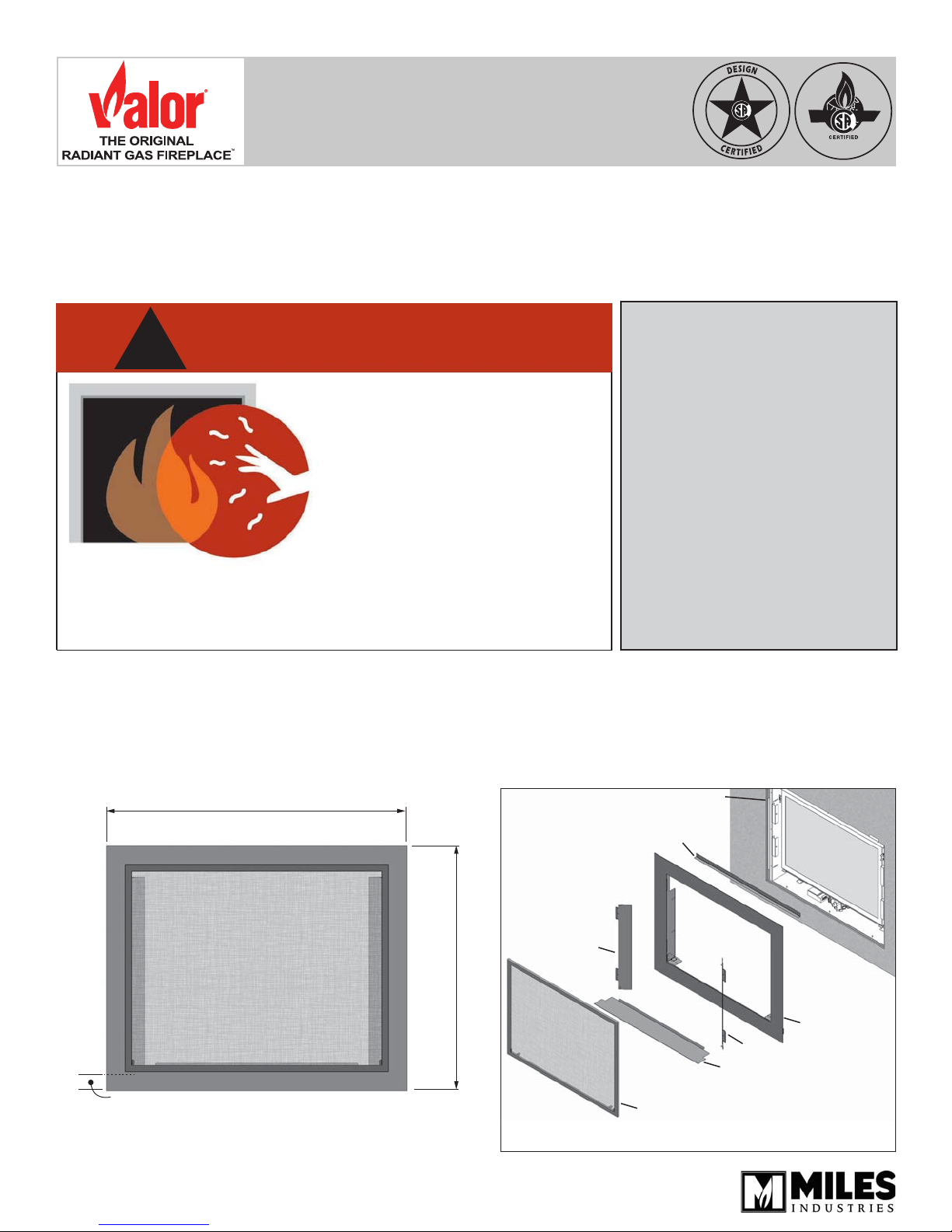
1440 Four-sided Trim Kit
Use with Valor 1400 Models only
Installation Instructions
!
A barrier designed to reduce the risk of burns from the hot
viewing glass is provided with this appliance and shall be
installed for the protection of children and other at-risk
individuals.
The 1440 trim is intended to be used on Valor heaters
models 1400. Mounting of the 1440 does not affect
clearances or other specifi cations listed in the heater
installation manuals—see installation manual supplied
with the heater for more information.
DANGER
HOT GLASS WILL
CAUSE BURNS.
DO NOT TOUCH GLASS
UNTIL COOLED.
NEVER ALLOW CHILDREN
TO TOUCH GLASS.
Note: Mounting of this trim allows for non-combustible
material up to 3/4” (19 mm) thick installed over top of
the required 1/2” (13 mm) cement board. For thicker
fi nishes, refer to appliance manual.
47-5/8” (1209 mm)
INSTALLER
Leave this manual
with the appliance.
CONSUMER
Retain this manual
for future reference.
1400 engine
1-1/2“ (38 mm) between bottom
of appliance and bottom of trim
4005086-02
© Copyright Miles Industries Ltd., 2016
38-7/8” (987 mm)
Linerbox bracket
LH door
Steel front panel
RH door
Plinth
Barrier screen
Overview
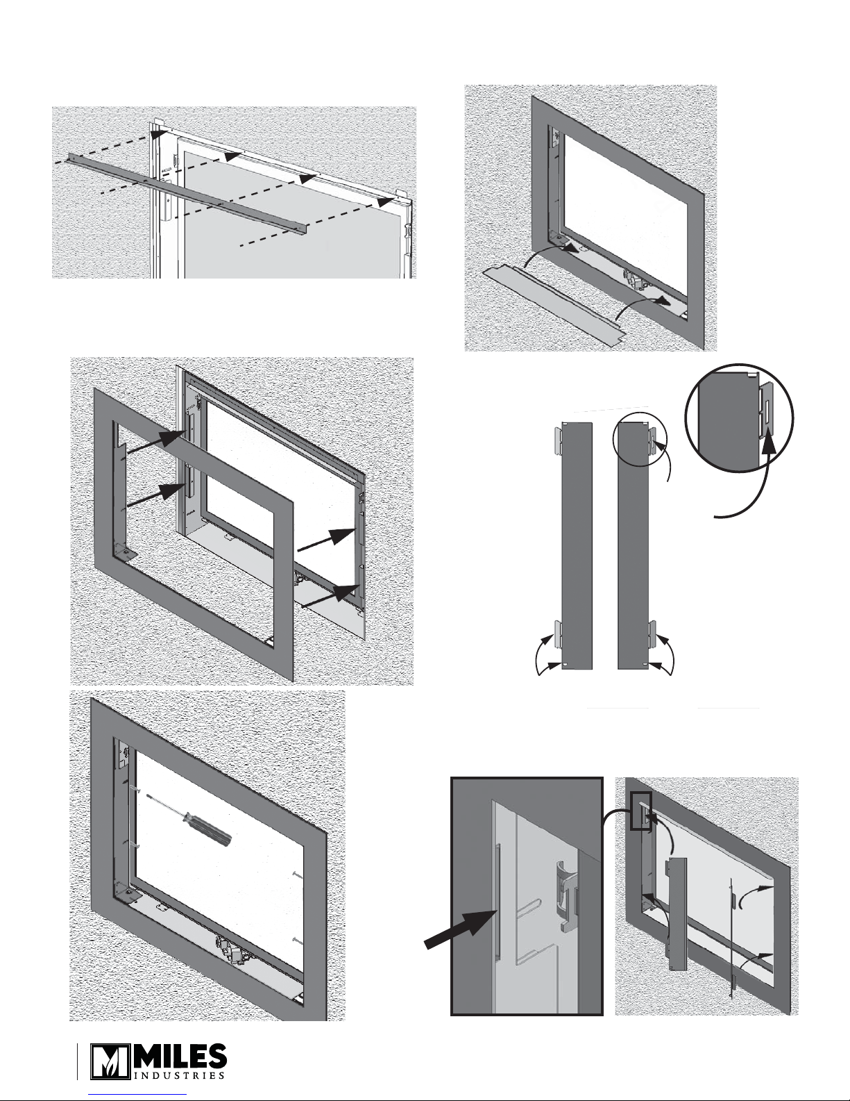
Installation
LH Door RH Door
nger grip inboard,
with locator on right
RH door has a
slot in upper
locator tab
nger grip inboard,
with locator on left
1. On completion of fi replace installation, screw the
liner bracket to top face of fi rebox with 4 screws.
2. Carefully position and secure steel front panel with
4 low profi le screws to 4 fi rebox mounting brackets;
before tightening, hold panel up against wall fi nish
then tighten.
3. Place plinth onto supports and push into place with
inside edge tucked behind front trim.
4. Identify left hand door from
right using diagram below.
2
5. Position LH door to left side of front panel, identify
door slots top and bottom just behind front panel
and slide door locator in position.
6. Repeat for other door.
 Loading...