

Valor 1430FFK Installation Instructions Manual
1-1/8”
(29 mm)
!
H6 SERIES
1430FFK Fixed Framing Kit
CSA approved for use with Valor Model 1400 Heaters ONLY
Installation Instructions
INSTALLER
DANGER
HOT GLASS WILL
CAUSE BURNS.
DO NOT TOUCH GLASS
UNTIL COOLED.
Leave this manual
with the appliance.
CONSUMER
Retain this manual
for future reference.
NEVER ALLOW CHILDREN
TO TOUCH GLASS.
A barrier designed to reduce the risk of burns from the hot
viewing glass is provided with this appliance and shall be
installed for the protection of children and other at-risk
individuals.
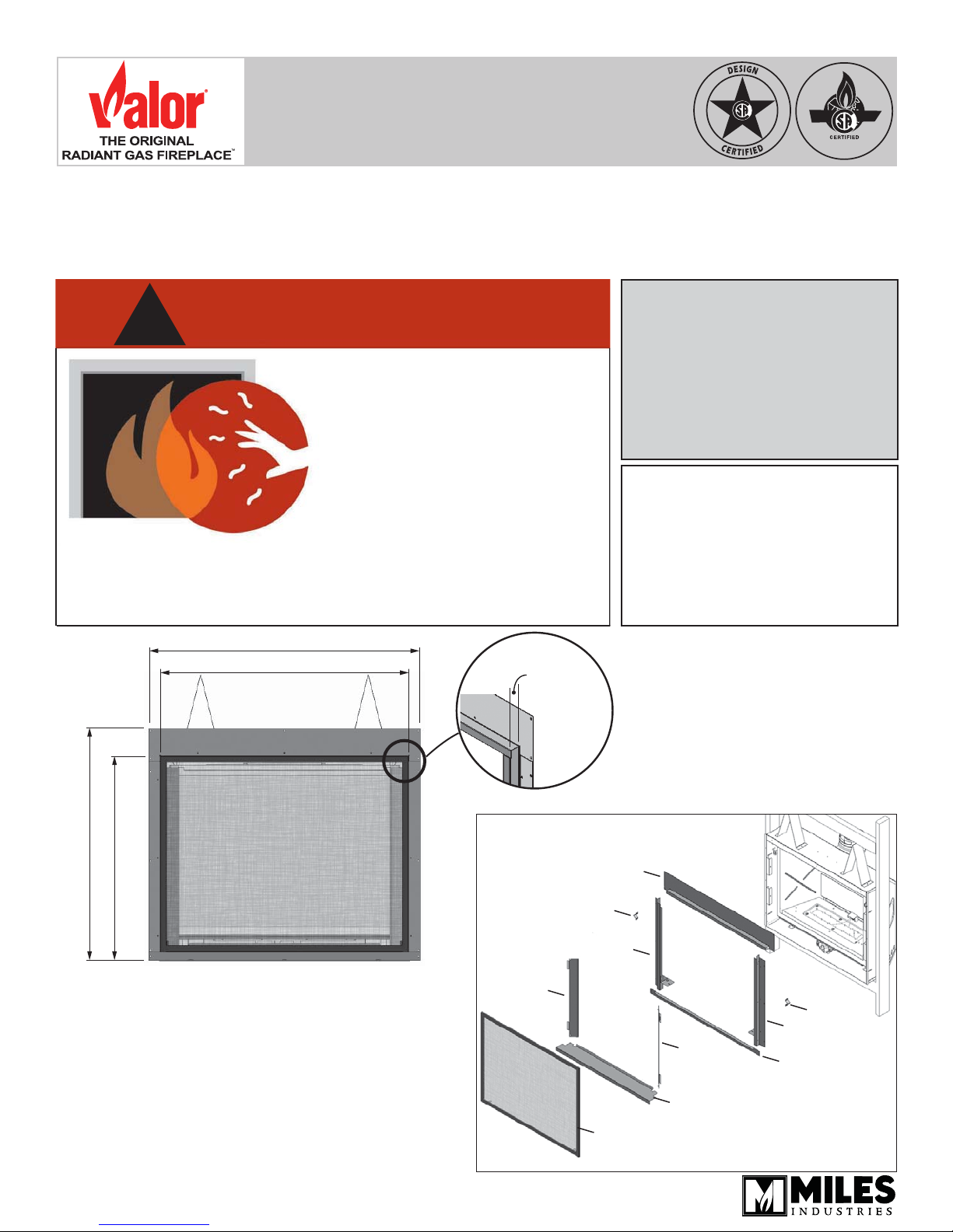
45-5/8” (1158 mm)
41-3/4” (1061 mm)
39” (991 mm)
33” (839 mm)
Upper panel
Stand-off
Note: This kit must be installed
by a qualifi ed installer, service
agency or gas supplier at the
time of the heater installation.
These instructions are to be used
in conjunction with the fi replace
main installation instructions.
1400 engine
The 1430FFK Fixed Framing Kit installs to the Valor
1400 appliance during the framing stage and the
appliance’s position is fi xed in the framing. Wall fi nishes
are then applied over top of the fl anges and butted up
to the frame of the 1430.
This kit is not intended and
an H6 trim or any other trim
See appliance installation manual for more
information about fi nishing around this kit.
4004907-04
© Copyright Miles Industries Ltd., 2016.
cannot be installed with
.
LH panel
LH door
Stand-off
RH panel
RH door
Lower panel
Removable panel
Barrier screen
Overview
Install Appliance with 1430 Fixed Framing Kit
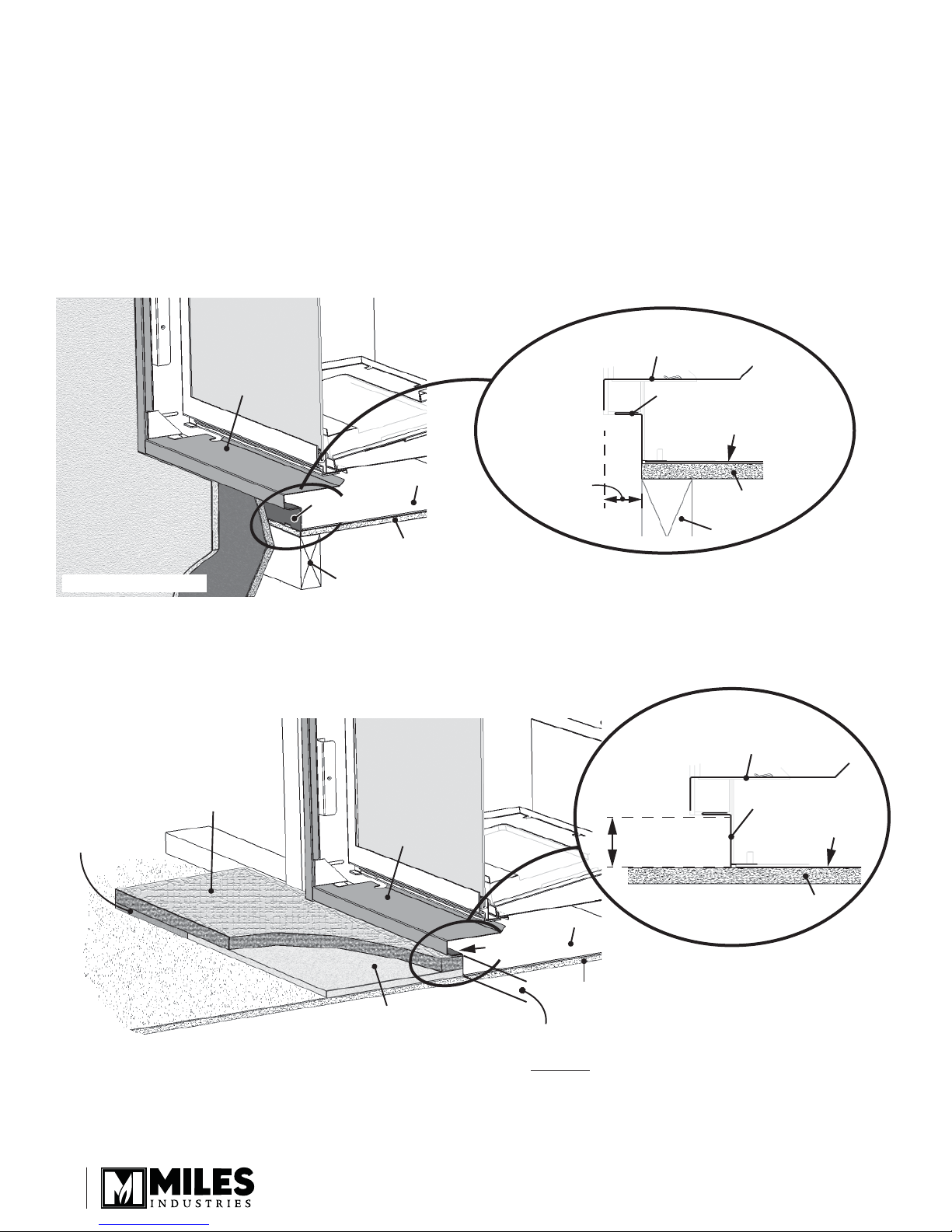
Lower panel
Removable panel
1-1/8”
(29 mm)
Front of
appliance
Stud
Plywood base
Appliance base
Lower panel
Removable panel
1-1/2” (38 mm)
Front of
appliance
Plywood
Appliance base
The side brackets provided loose with the appliance
are not needed with this kit.
Hearth considerations
You need to know whether there will be a hearth or
not in front of the appliance and some rules must be
considered:
Without hearth
In the case where there is no hearth, the bottom of the
appliance must be raised at least 4” inches above any
combustible fl oor in front.
Removable panel
Appliance base
Lower panel
Finishing up the wall
With hearth
Any hearth within 4” vertical of the base of the heater
must be non-combustible. See Hearth Requirements
section of the manual packed with the appliance.
1/2” combustible
shim at ends to
match Micore
Finishing with hearth
2
Non-combustible
material
Plywood
base
Stud
Removable panel
1/2” insulating Micore panel
(supplied with appliance)
Section view, up the wall—detail
Appliance base
Lower panel
Section view,
Plywood
sub-oor
1-1/2” (38 mm)
max. thickness
(including Micore)
hearth—detail
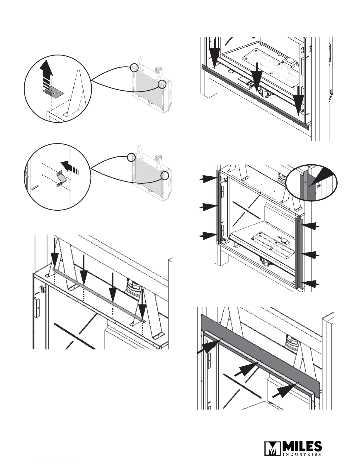
Installation at time of framing
1. On the top of the appliance’s case in front of the
stand-off s, remove the positioning brackets (2
screws each); they are not used with this kit.
2. On the sides of the appliance case, install the side
stand-off s (2 screws each).
4. Install the lower panel using the three studs at the
base of the appliance (3 nuts).
5. On the appliance, install the side panels as
indicated (3 screws per side).
3. Fit the upper panel support to the top of the
appliance’s case as indicated (5 screws).
6. Install the upper panel as indicated (3 screws).
3
 Loading...