

Valor 1400IN, 1400IP Installation & Owner's Manual
H6 SERIES
DV ZC Gas Fireplaces
1400IN (NG) & 1400IP (LPG)
Installation & Owner’s Manual
!
A barrier designed to reduce the risk of burns from the hot
viewing glass is provided with this appliance and shall be
installed for the protection of children and other at-risk
individuals.
! WARNING
FIRE OR EXPLOSION HAZARD
Failure to follow safety warnings exactly
could result in serious injury, death, or
property damage.
— Do not store or use gasoline or other
fl ammable vapors and liquids in the
vicinity of this or any other appliance.
— WHAT TO DO IF YOU SMELL GAS
▪ Do not try to light any appliance.
▪ Do not touch any electrical switch; do
not use any phone in your building.
▪ Leave the building immediately.
▪ Immediately call your gas supplier from
a neighbor’s phone. Follow the gas
supplier’s instructions.
▪ If you cannot reach your gas supplier,
call the fi re department.
— Installation and service must be
performed by a qualifi ed installer, service
agency or the gas supplier.
DANGER
HOT GLASS WILL
CAUSE BURNS.
DO NOT TOUCH GLASS
UNTIL COOLED.
NEVER ALLOW CHILDREN
TO TOUCH GLASS.
This manual contains instructions to install the
ENGINE ONLY. A trim kit is REQUIRED to
complete the installation. A barrier screen is
provided with the trim kit. Refer to the manual
supplied with the trim for installation.
This appliance may be installed in an
after-market permanently located,
manufactured (mobile) home where not
prohibited by local codes.
This appliance is only for use with the type
of gas indicated on the rating plate. This
appliance is not convertible for use with
other gases, unless a certifi ed kit is used.
This appliance is a domestic room-heating
appliance. It must not be used for any other
purposes such as drying clothes, etc.
This appliance is suitable for installation in a
bedroom or bed sitting room.
Ce guide est disponible en français sur demande.
INSTALLER
Leave this manual
with the appliance.
CONSUMER
Retain this manual
for future reference.
Please read this manual
BEFORE installing and
operating this appliance.
4004905-03
©2015, Miles Industries Ltd.
Table of Contents
W
A
R
R
A
N
T
Y
P
R
O
G
R
A
M
V
A
L
O
R
C
O
M
F
O
R
T
V
A
L
O
R
C
O
M
F
O
R
T
FOR THE OWNER FOR THE QUALIFIED INSTALLER
Safety Precautions ................................................. 3
Safety and Your Fireplace ...................................... 4
Owner’s Information ............................................... 5
Operating Your Fireplace for the First Time ...............5
Cleaning Your Fireplace ............................................6
Checking Pilot and Burner Flames ............................8
Replacing Batteries ...................................................8
Using Handset Wall Holder ........................................9
Locating Lighting, Operation and Rating Information
Card ........................................................................9
Servicing Your Fireplace ............................................9
Operating Your Fireplace ...........................................9
How to Turn Your Fireplace OFF
(including pilot) .....................................................10
How to Ensure Your Fireplace Cannot
Be Turned ON Inadvertently .................................10
Remote Control Operation ................................... 11
Options .................................................................. 16
Lighting Instructions ............................................ 17
Warranty ................................................................68
R
O
M
L
A
R
A
G
Warranty Card at the
back of this manual.
W
O
V
R
P
Y
T
T
N
A
R
R
R
A
O
C
F
O
M
Massachusetts: The piping and fi nal gas connection
must be performed by a licensed plumber or gas fi t-
ter in the State of Massachusetts. Also, see Carbon
Monoxide Detector requirements on page 18.
The information contained in this installation manual is
believed to be correct at the time of printing. Miles Industries Ltd. reserves the right to change or modify any
information or specifi cations without notice. Miles Indus-
tries Ltd. grants no warranty, implied or stated, for the
installation or maintenance of your heater, and assumes
no responsibility for any consequential damage(s).
Commonwealth of Massachusetts......................18
Specifi cations ....................................................... 20
Overview................................................................21
Dimensions & Location ........................................ 22
Mantel & Hearth Clearances ................................23
Hearth Requirements ........................................... 25
Framing Requirements ........................................28
Venting ...................................................................32
Co-axial Venting....................................................33
Co-linear Venting .................................................. 37
Installation Planning ............................................39
Appliance Height in Framing ...................................39
Appliance Depth in Framing ....................................39
Plan Wall Finish .......................................................40
Installation ............................................................. 42
Unpack Appliance ....................................................42
Fit Standoffs ............................................................42
Remove Heat Shield ................................................42
Convert from Top to Rear Outlet (if required) ..........42
Remove Window .....................................................43
Install Appliance for 1430 Fixed Framing Kit ...........44
Install Appliance for 3 and 4-Sided Surrounds ........48
Install Electrical Wiring (if necessary) .....................51
Connect Gas Supply ................................................52
Install Liners ............................................................53
Install Driftwood Kit 1400DWK ................................54
Install Decorative Glass Murano 1400DGM ............56
Install Decorative Glass Set 1400DGS ....................57
Install Traditional Log Kit 1400LSK ..........................58
Refi t Window ...........................................................61
Remote Control Initial Pairing ..................................62
Check Operation ......................................................63
Adjust Aeration if needed .........................................63
Install Surround and Barrier Screen ........................64
Install Remote Control Handset Wall Holder ...........64
Wiring Diagram .....................................................65
Approved Venting Components .......................... 66
Warranty ................................................................68
Spare Parts............................................................69
Index ...................................................................... 72
190–2255 Dollarton Highway, North Vancouver, BC, CANADA V7H 3B1
2
Designed and Manufactured by / for
Miles Industries Ltd.
Tel. 604-984-3496 Fax 604-984-0246
www.valorfi replaces.com
© Copyright Miles Industries Ltd., 2015. All rights reserved.
Safety Precautions
!
READ and UNDERSTAND all instructions carefully
before starting the installation. FAILURE TO FOLLOW
these installation instructions may result in possible fi re
hazard and will void the warranty.
Prior to the fi rst fi ring of the fi replace, READ the
Owner’s Information section of this manual.
DO NOT USE this appliance if any part has been under
water. Immediately, CALL a qualifi ed service technician
to inspect the unit and to replace any part of the control
system and any gas control that has been under water.
THIS UNIT IS NOT FOR USE WITH SOLID FUEL.
Installation and repair should be PERFORMED by a
qualifi ed service person. The appliance and venting
system should be INSPECTED before initial use and at
least annually by a professional service person. More
frequent cleaning may be required due to excessive
lint from carpeting, bedding, etc. It is IMPERATIVE that
the unit’s control compartment, burner, and circulating
air passageways BE KEPT CLEAN to provide for
adequate combustion and ventilation air.
Always KEEP the appliance clear and free from
combustible materials, gasoline, and other fl ammable
vapors and liquids.
NEVER OBSTRUCT the fl ow of combustion and
ventilation air. Keep the front of the appliance CLEAR
of all obstacles and materials for servicing and proper
operation.
This unit MUST be used with a vent system as
described in this installation manual. NO OTHER vent
system or components MAY BE USED.
This gas fi replace and vent assembly MUST be vented
directly to the outside and MUST NEVER be attached
to a chimney serving a separate solid fuel burning
appliance. Each gas appliance MUST USE a separate
vent system. Common vent systems are PROHIBITED.
INSPECT the external vent cap on a regular basis to
make sure that no debris, plants, trees, shrubs are
interfering with the air fl ow.
TURN OFF the gas before servicing this appliance.
It is recommended that a qualifi ed service technician
perform an appliance check-up at the beginning of each
heating season.
DO NOT use this heater as a temporary source of heat
during construction.
State of California. Proposition 65 Warning. Fuels
used in gas, wood-burning or oil fi red appliances,
and the products of combustion of such fuels, contain
chemicals known to the State of California to cause
cancer, birth defects and other reproductive harm.
California Health & Safety Code Sec. 25249.6.
Due to the high temperature, the appliance should be
LOCATED out of traffi c areas and away from furniture
and draperies.
Clothing or fl ammable material SHOULD NOT BE
PLACED on or near the appliance.
This appliance is a DOMESTIC ROOM-HEATING AP-
PLIANCE. It must not be used for any other purposes
such as drying clothes, etc.
DO NOT place furniture or any other combustible
household objects within 36” of the fi replace front.
BE CAREFUL not to put any decorating objects
sensitive to heat to close above or around the fi replace
as it gets very hot when operating.
The glass door assembly MUST be in place and sealed
before the unit can be placed into safe operation.
DO NOT OPERATE this appliance with the glass door
removed, cracked, or broken. Replacement of the glass
door should be performed by a licensed or qualifi ed
service person. DO NOT strike or slam the glass door.
The glass door assembly SHALL ONLY be replaced
as a complete unit, as supplied by the fi replace
manufacturer. NO SUBSTITUTE material may be used.
DO NOT USE abrasive cleaners on the glass door
assembly. DO NOT ATTEMPT to clean the glass door
when it is hot.
A BARRIER DESIGNED TO REDUCE THE RISK OF
BURNS from the hot viewing glass is provided with
this appliance and SHALL BE INSTALLED for the
PROTECTION OF CHILDREN and other AT-RISK
INDIVIDUALS.
If the barrier becomes damaged, the barrier SHALL BE
REPLACED with the MANUFACTURER’S BARRIER
for this appliance.
Any safety screen, guard or barrier removed for servicing the appliance, MUST BE REPLACED prior to
operating the appliance.
Children and adults should be ALERTED to the hazards
of high surface temperature and should STAY AWAY to
avoid burns or clothing ignition.
YOUNG CHILDREN should be CAREFULLY
SUPERVISED when they are in the same room as the
appliance. Toddlers, young children and others may
be susceptible to ACCIDENTAL CONTACT BURNS.
A physical barrier is recommended if there are at-risk
individuals in the house. To restrict access to a fi replace
or stove, INSTALL AN ADJUSTABLE SAFETY GATE
to keep toddlers, young children and other at-risk
individuals out of the room and away from hot surfaces.
3
Safety and Your Fireplace
!
Safety and Your Fireplace
Please Read and Carefully Follow all Safety Warnings and
Operating Instructions Contained in Your Owner’s Manual
(Replacement Manuals are available by contacting our service department at
1-800-468-2567 or visit www.valorfi replaces.com).
Please Follow These Important
Child Safety Precautions and
Recommendations,
• Parts of your Valor Fireplace become
extremely hot while in operation.
• The glass viewing window
temperature can
exceed 500 F
at full capacity.
Momentary contact
with a hot glass
surface can cause
a severe burn, even if the fi replace
is operating at reduced heating
capacity.
• The glass window will remain hot
for an extended period of time after
the fi replace has been turned off.
Ensure that children are prevented
from touching the fi replace during the
cool down period.
• Toddlers and Young Children
must be closely supervised at all
times when they are in the same
room as the operating fi replace. They
lack full awareness of danger and
rely on your protection. Toddlers,
in particular , do not have the motor
skills and response refl exes to
withdraw in the event of accidental
contact with a hot surface.
• A physical barrier is strongly
recommended if there are young
children, or at-risk individuals in the
house. Install an approved aftermarket safety gate to keep toddlers,
young children and other at-risk
individuals a safe distance from the
fi replace.
• Keep the remote control handset
out of reach of children at all
times. A wall mount storage holster
is provided with your remote control
handset.
• Ensure that the fi replace, including
the pilot light, is completely turned
off when children are present and
close supervision and safety barriers
are not available—see pages 9–10 of
Owner’s Information section.
• If the fi replace is not going to be used
for the summer or any extended
period of time, remove the batteries
from the remote control handset
and receiver. It is recommended that
batteries are replaced annually in any
event—see page 8.
4
Owner’s Information
• • Some materials or items, although safe, may
discolor, shrink, warp, crack, peel, and so on
because of the heat produced by the fi replace.
AVOID PLACING
candles, paintings, photos,
and other items
SENSITIVE TO HEAT
• • Solid wood fl ooring in front of the fi replace (if
allowed) may shrink during the heating season
due to heat.
OWNER’S
INFORMATION
WARNING
!
EXTREMELY HOT!!!
• READ the SAFETY information on pages
3 and 4 of this manual BEFORE operating
your gas heater.
• Some parts of your fi replace are EXTREMELY
HOT, particularly the GLASS window.
• DO NOT LET CHILDREN touch the glass or
any parts of your fi replace even after it is
turned off as it is still hot.
• USE THE BARRIER SCREEN provided with
the trim or a GATE to reduce the risk of severe
burns.
• Keep the remote control handset OUT OF
REACH of children.
• HOT WALL SURFACES! The wall directly above
the fi replace is VERY HOT when the fi replace
heats. It is constructed of non-combustible
materials and although safe, it may reach
temperatures in excess of 200º F depending
on choice of trims. DO NOT TOUCH IT!
• HOT HEARTH/FLOOR SURFACE! The
hearth or fl oor directly in front of the fi replace
is VERY HOT when the fi replace heats. Even
if constructed of non-combustible materials,
and although safe, it may reach temperatures
in excess of 200º F depending on choice of
materials. DO NOT STEP ON IT!
Some materials or items, although safe, may
discolor, shrink, warp, crack, peel, and so on
because of the heat produced by the fi replace.
AVOID PLACING
and other items
36 inches (0.9 m) around the fi replace.
Solid wood fl ooring in front of the fi replace (if
allowed) may shrink during the heating season
due to heat.
Performance of LPG appliances may be affected by
the quality of commercial gas supplied in your area.
candles, paintings, photos,
SENSITIVE TO HEAT
within
Thank You ...
For purchasing a Valor by Miles Industries. Your new
radiant gas heater is a technical appliance that must
be installed by a qualifi ed dealer. Each Valor fi replace
is fully tested during the production process for your
safety and comfort.
Your unit has been professionally installed by:
Dealer Name: ________________________________
Phone Number :_______________________________
Should you encounter an operational problem, call
your dealer immediately.
Do not try to repair the unit as you may cause an
injury or damage the fi replace.
This manual and particularly the preceeding
and following pages contain very important
information regarding the safe operation of your
fi replace as well as maintenance instructions.
Read carefully BEFORE operating your fi replace
and pay special attention to the SAFETY
WARNINGS.
A heating gas appliance does require safe handling
and for this reason, we very strongly recommend that
no children be allowed to touch the fi replace and its
controls at all times. Do install a screen or barrier
in front of the fi replace to protect your children
against severe burns.
Operating Your Fireplace for the First Time
When operating your new fi replace for the fi rst time,
some vapors may be released due to the burning of
curing compounds used in the manufacture of the
appliance. They may cause a slight odor and could
cause the fl ames to be the full height of the fi rebox, or
even slightly higher, for the fi rst few hours of operation.
It is also possible that these vapors could set off any
smoke detection alarms in the immediate vicinity.
These vapors are quite normal on new appliances. We
recommend opening a window to vent the room. After
a few hours use, the vapors will have disappeared and
the fl ames will be at their normal height.
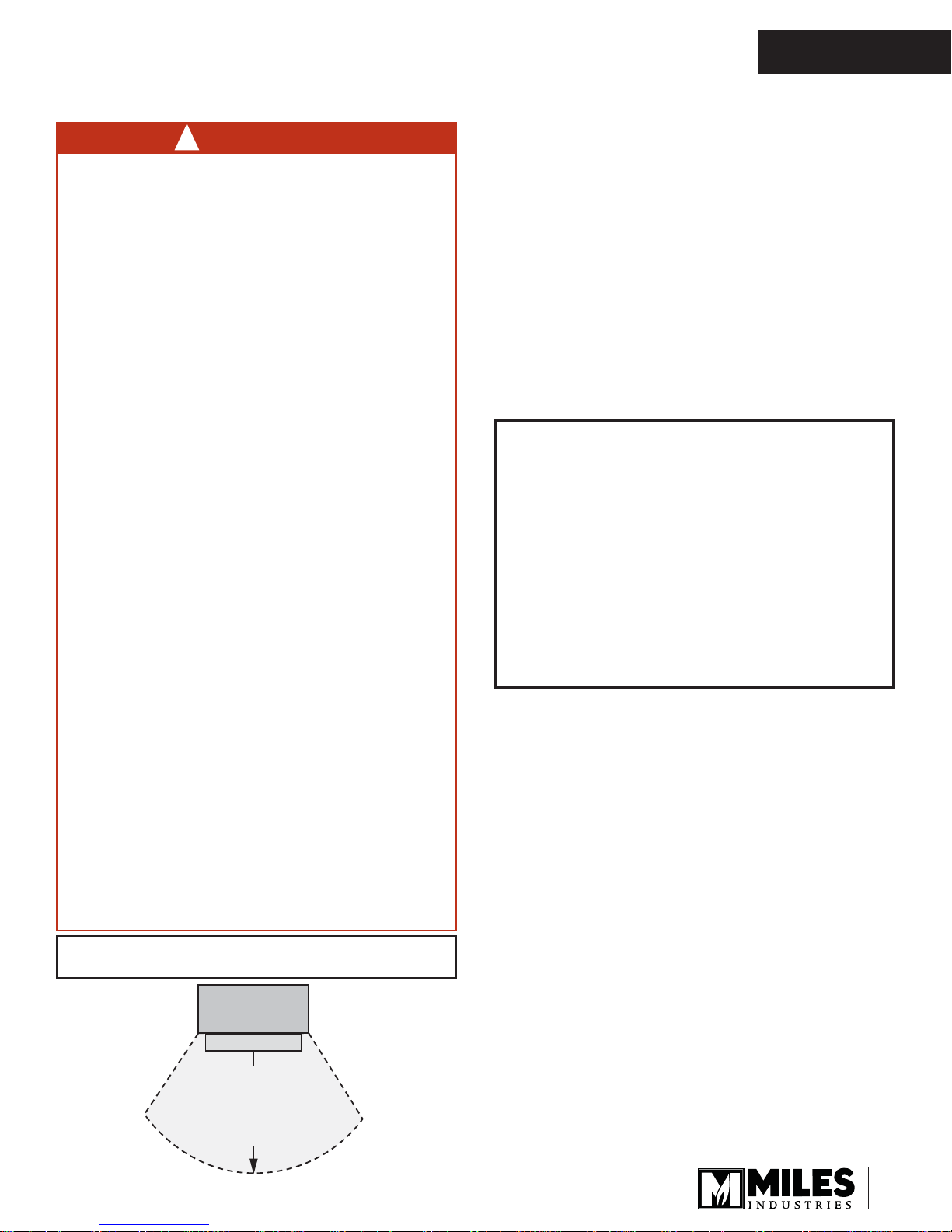
Fireplace
Hearth
Do not put
furniture or other objects
in this space in front of
the replace:
36” (0.9 m)
Flame Supervision Device
For your safety, this appliance is fi tted with a fl ame
supervision device which will shut-off the gas supply
if, for any reason, the pilot fl ame goes out. This device
incorporates a fi xed probe, which senses the heat
from the pilot fl ame. If the probe is cool, the device will
prevent any gas fl ow unless manually lighting the pilot.
See full lighting instructions on page 17 of this manual.
5
OWNER’S
INFORMATION
Owner’s Information
Cleaning Your Fireplace
WARNING
!
DO NOT TOUCH THE GLASS WHILE IT IS HOT!
Let the fi replace cool fi rst before cleaning it.
Important - Glass cleaning - Mineral deposits
One of the by-products of the combustion process in
a gas appliance is a mineral which can show up as a
white fi lm on the ceramic glass of the viewing door.
The composition of the deposit varies with location and
time. It is believed to be associated with the varying
sulfur content of the gas. You may have the problem
intermittently.
We have consulted with ceramic glass manufacturers
and they cannot offer a defi nitive solution to this prob-
lem. Dealers have tried various cleaning products with
varying results. The following are recommendations
only and are not meant to guarantee results.
NOTE: This is a problem beyond Miles Industries’
control and is not covered under warranty.
• Clean the glass regularly as soon as you notice
the buildup (white fi lm). If the fi lm is left for a longer
period of time, it will etch into the glass. It is then
much harder, if not impossible, to remove.
• NEVER use an abrasive cleaner or a ammoniabased cleaner on the ceramic glass. Any
abrasion of the surface has the immediate effect of
compromising the strength of the glass. An emulsion
type cleaner is recommended.
• Use a soft damp cloth to apply the cleaner. Dry the
glass with a soft, dry, preferably cotton cloth. Most
paper towels and synthetic materials are abrasive to
ceramic glass and should be avoided.
• Our dealers have had good results from the
products listed below. We cannot, however,
guarantee the results of these products.
• Brasso, Polish Plus by Kelkem, Cook Top Clean
Creme by Elco, White Off by Rutland, Turtle Wax
Do not clean the glass while it is hot!
Always securely replace the window and the barrier
screen before lighting.
If broken, the glass pane may only be replaced
as a complete window unit as supplied by the
manufacturer.
If the barrier becomes damaged, the barrier shall
be replaced with the manufacturer’s barrier for this
appliance.
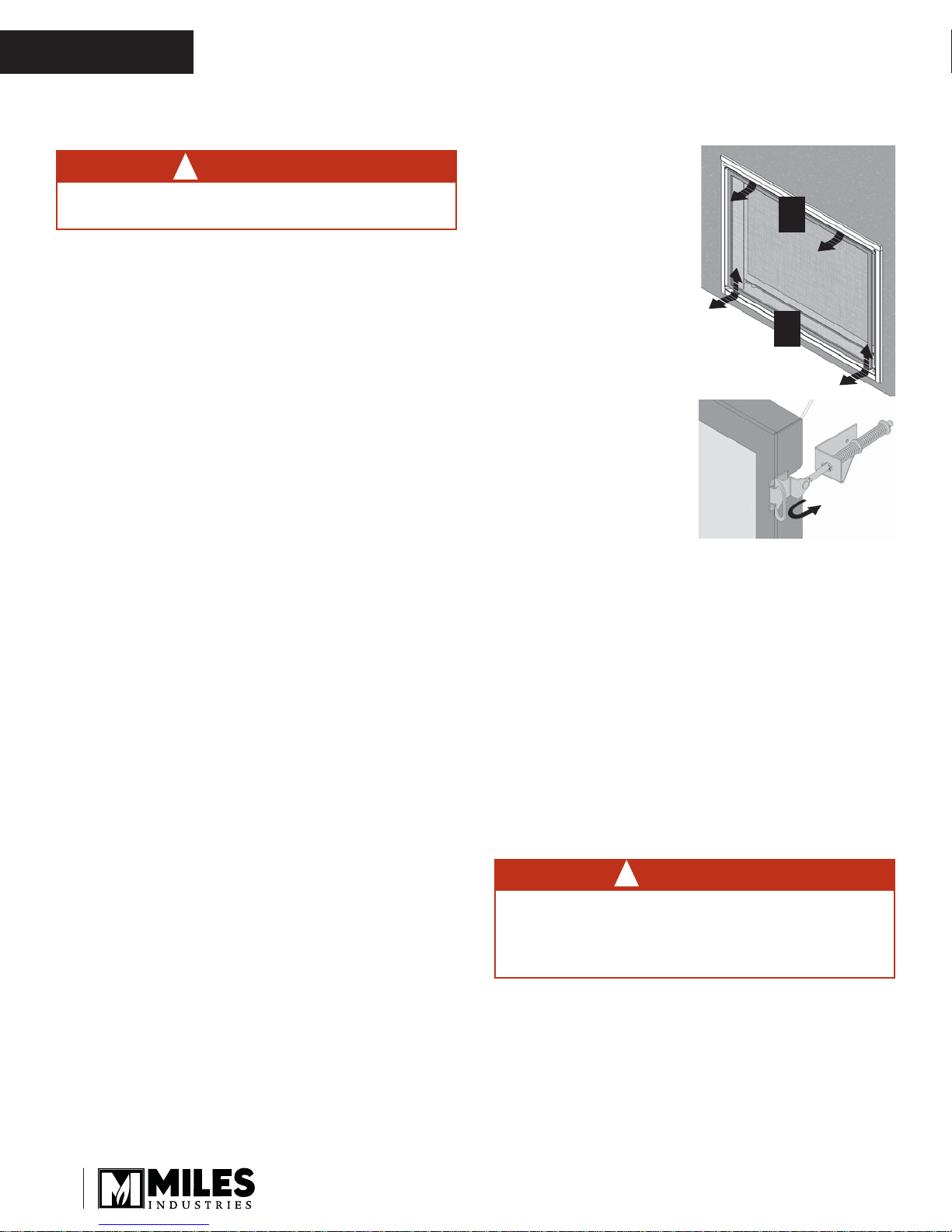
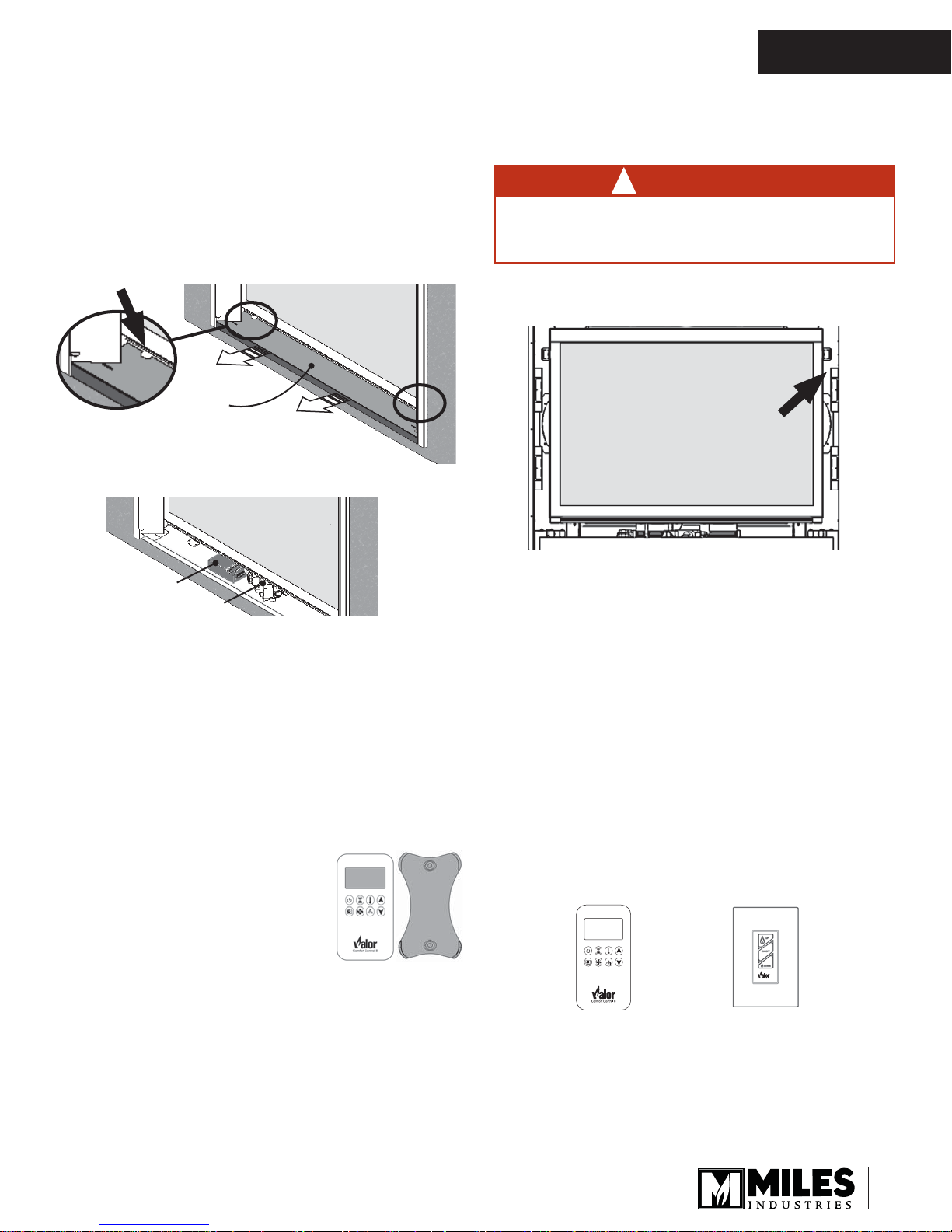
To remove the window for cleaning:
1. Remove the barrier
screen. Slide the screen
up to disengage the
bottom tabs then unhook
the top tabs.
2. Remove the side panels
by pulling them sideways
towards the center,
sliding them out of their
slots behind the trim
face.
3. Find the levers on each
side of the window
towards the top. Using
your fi nger, pull the
levers towards you and
unhook them from the
window frame brackets.
4. Gently pull the top of the
window outward.
5. Lift the window out of its
bottom railing and set it aside in a safe place to
avoid damage.
Clean the window following the guidelines in this section.
Clean the steel trims with mild soap and warm water.
Any alcohol/solvent base cleaner will weaken the coating and damage it.
Clean the barrier screens dusting with a soft brush.
Clean the fi rebox ceramic logs/rocks and walls dust-
ing them with a soft brush. Dust can also be removed
from the burner using a soft brush after removing the
ceramic logs. When cleaning, make sure that no par-
ticles are brushed into the slots of the burner.
WARNING
!
b
a
Spring Loaded
Window Levers
CHOKING HAZARD! Ensure that the fi replace
area is clear of fi reglass or shale particles as
these could be ingested by small children. Vacuum
thoroughly around the fi replace area after cleaning.
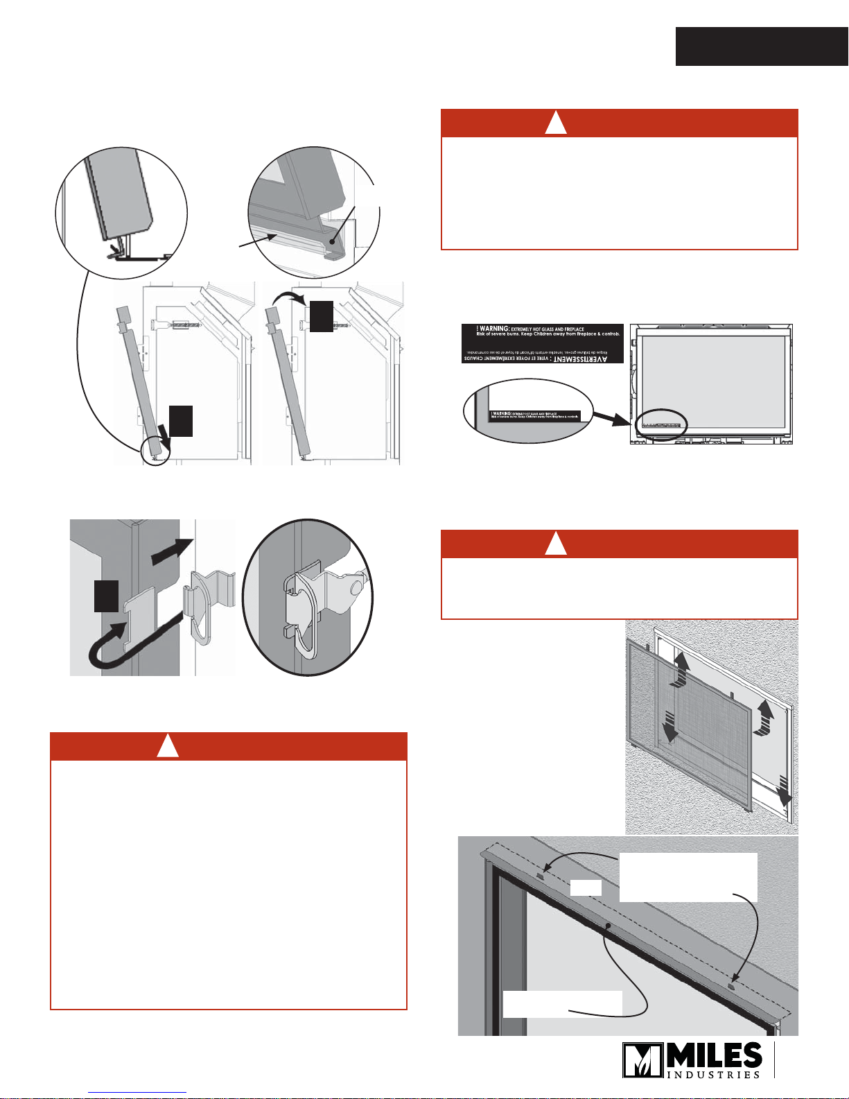
To refi t the window:
1. Place the window in its bottom support railing.
Ensure to remove any shale or glass particles
in the railing before installing the window.
6
Owner’s Information
OWNER’S
INFORMATION
2. Push the top of the window frame against the
fi rebox.
Window
frame
Bottom
support
railing
2
1
3. While you hold it, pull the side levers back into the
window brackets on each side.
WARNING
!
Failure to install the window correctly can
leak carbon monoxide, affect the performance
of the fi replace, damage components, cause
overheating resulting in dangerous conditions.
Damage caused by incorrect window installation is not covered by the Valor warranty.
5. If the Hot Glass Warning plate has been removed
from the front lower corner of the window,
reinstall it by sliding it between the glass and
the frame as indicated.
Hot Glass Warning Plate
6. Reinstall the side doors sliding them sideways to
insert their tabs behind the front face of the trim.
7. Reinstall the barrier screen on the trim.
3
4. Apply fi rm hand pressure around the window frame to
ensure the window is sealed tight against the fi rebox.
DANGER
!
The window unit must be correctly installed,
fastened and sealed after servicing or serious
bodily injury and/or damage to the appliance
may result.
To ensure a safe operation:
• Double-check that the bottom of the window
frame is correctly installed in the bottom
support railing;
• Verify that the levers are hooked properly to
the window tabs then;
• Pull out the top of the window and release it
to insure the springs return it;
• Ensure the window is sealed before operation.
WARNING
!
FOR SAFETY PURPOSE, ensure the barrier
screen is re-installed on the fi replace front after
maintenance.
Insert the screen’s top
tabs in the slots on
the underside of the
convectio n baffl e or
heatshield, then insert
the screen’s bo ttom
tabs in the slots of the
removable panel at
the bottom to lock it in
position.
Barrier screen’s top tabs
coming through slots in
Trim
Convection baffl e or
heatshield
baffl e/heatshield (behind
the face of the trim)
7
OWNER’S
INFORMATION
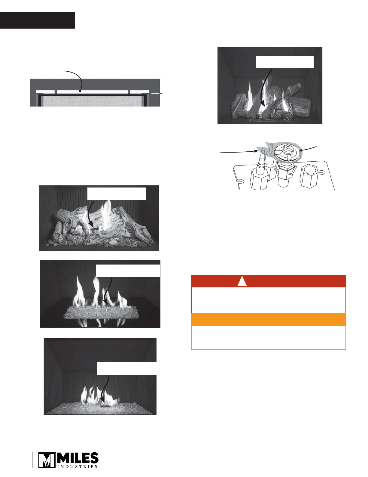
Ensure the screen is secure and seated all the way
down into the bottom slots. There should be a 1”
gap between the top of the barrier screen and the
trim.
8. Verify that the screen is properly hooked and
secure.
Owner’s Information
Checking Pilot and Burner Flames
A periodic check of the pilot and burner fl ames should
be made. Check after the fi re has been on for at least
30 minutes. The pilot fl ame must cover the tip of the
thermocouple probe. The main burner fl ame pattern will
vary from appliance to appliance depending on the type
of installation and climatic conditions.
Pilot Flame can be seen
under the right rear logs
1400 Driftwood Kit— Correct Flame Picture
Pilot Flame can be seen
under the rear log
1400 Log Set—Correct Flame Picture
Thermocouple
Probe must be in
Flame
Pilot Flame
The appliance area must always be kept clear and
free from combustible materials, gasoline and other
fl ammable vapors and liquids.
Inspect the vent terminal outdoors regularly to make
sure that snow, trees, bushes, leaves, or other objects
do not obstruct it.
Examine the vent system and terminal regularly. We
recommend annually.
Pilot Flame can be seen at
the back of the fi re bed
1400 Decorative Glass Murano—Correct Flame Picture
Pilot Flame can be seen at
the back of the fi re bed
1400 Decorative Glass Set—Correct Flame Picture
Replacing Batteries
WARNING
!
DO NOT ATTEMPT TO CHANGE THE BATTER-
IES WHILE THE FIREPLACE IS STILL HOT! Let
the fi replace cool fi rst before touching it.
CAUTION
DO NOT USE a screwdriver or other metallic
object to remove the batteries from the receiver or
the handset! This could cause a short circuit.
Low batteries signal: see page 15.
The appliance uses four 1.5 V AA alkaline batteries
for its receiver and two AAA alkaline battery for its
handset. Batteries should last one to two seasons,
depending on usage. Removing the batteries in the offseason will extend the battery life.
8
Owner’s Information
OWNER’S
INFORMATION
To replace the batteries in the receiver:
The receiver is located to the left side of the gas valve
under the removable panel in front of the appliance.
1. Remove the barrier screen and the removable
panel. It is not necessary to remove the side doors.
Note: If it is diffi cult to pull out the panel from its
front edge, use your fi nger and pull from the notches
in the panel at the bottom of the window.
Removable
panel
2. Pull the receiver out.
Receiver
Gas valve
Locating Lighting, Operation and Rating
Information Card
WARNING
!
DO NOT ATTEMPT TO TOUCH THE INFORMATION CARD WHILE THE FIREPLACE IS STILL
HOT! Let the fi replace cool fi rst before touching it.
The Lighting, Operation and Rating Information card is
located at the right-hand side of the fi rebox.
To access the information card, remove the barrier
screen and the right-hand side door. Pull it out and
read the important information on both sides.
3. Slide the receiver battery compartment’s cover off.
4. Replace the batteries with 4 AA alkaline batteries
orienting them as indicated inside the compartment.
5. Replace the cover.
6. Put the receiver back in its location at the left of the
gas valve.
7. Reinstall the removable panel sliding it back under
the side doors until it is fl ush with the sides of the
trim.
8. Reinstall the barrier screen.
Using Handset Wall Holder
Your fi replace equipment includes
a wall holder to store the handset.
If it hasn’t be installed, refer to the
instructions further on in this manual
for the installation.
Servicing Your Fireplace
If any attention is required for your appliance, contact
your supplier quoting the model number. It will be
helpful if the appliance’s serial number can also
be quoted. This number is on the rating card. The
replacement parts are shown at the end of this manual.
Please always quote the part number and description
when requesting spare parts.
Operating Your Fireplace
There are two ways to control your fi replace.
1. Thermostatic Remote Control;
2. Wall Switch (optional).
Thermostatic
Remote Control
The Thermostatic Remote Control can be programmed
to function automatically—see pages 11–15.
Wall Switch
(optional)
The Wall Switch can be used to turn on, off and to
increase or decrease the fl ame height—see the
1265WSK—Wall Switch Kit.
9
OWNER’S
INFORMATION
Owner’s Information
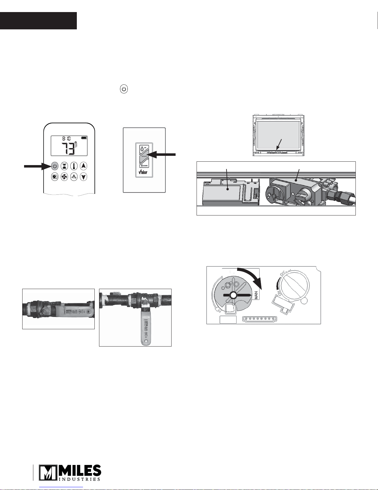
How to Turn Your Fireplace OFF
(including pilot)
Familiarize yourself with each of the following methods
before operating your fi replace.
Press and hold for 4 seconds the button on the
handset or OFF button on the optional wall switch.
NOTE: The fi rst tap on the button “wakes up” the
handset. Tap again to use the function.
AM
Remote control handset
If the fl ames are on, they go down and you hear the
valve motor wind down. You hear a clunk and a beep
indicating that the valve has received the signal from
the remote control.
As well, familiarize yourself with the gas shut-off valve
location in your house. As indicated below, the gas is
running when the handle is parallel with the pipe. The
gas is off when the handle is perpendicular with the
pipe.
Wall Switch
(optional)
How to Ensure Your Fireplace Cannot
Be Turned ON Inadvertently
You can use one of the two following methods to
ensure that your fi replace will not turn on when you
don’t want it on.
First, ensure your fi replace is turned off—including
the pilot—and cold BEFORE going ahead.
Receiver Gas valve
• Turn the dial on the gas valve from the ON position
to the MAN position as shown. Turning the dial to
MAN (arrow up) will ensure that the main burner
can not come on. The pilot will remain on if it is lit.
ON
ON: parallel to pipe
OFF:
perpendicular
to pipe
10
Gas valve
• Alternately, remove all batteries from the receiver
as well as the battery from the handset.
Automatic Shut-Off (in certain conditions)
Your fi replace’s remote control is equipped with an
automatic shut-off mechanism which is activated in
certain conditions. See page 15 in the Remote Control
Operation section for a description of this feature.
Remote Control Operation
OWNER’S
INFORMATION
NOTE: Before using the remote control system for
the fi rst time, the receiver and the handset must be
paired. See the section Remote Control Initial Pairing
on page 61 of this manual.
CHOOSING ONE-BUTTON OR TWO-BUTTON IGNITION
CHOOSING ONE-BUTTON OR TWO-BUTTON IGNITION
On this remote control handset, you can choose a one-button or
two-button ignition. Y ou can also choose to activate or disactivate
some of the functions. By default, the handset is set to a one-button ignition.
To change from 1-button ignition to 2-button ignition, remove
the batteries, wait 10 seconds, reinsert them and immediately
when the display flashes, press and hold the button for 10
seconds. is displayed and is flashing. When change is
complete changes to .
To change from two-button ignition to one-button ignition, proceed
the same way as above. is displayed and is flashing. When
change is complete changes to .
DEACTIVATING OR ACTIVATING FUNCTIONS
DEACTIVATING OR ACTIVATING FUNCTIONS
Some functions can be deactivated or activated.
Deactivate Functions
.gnihsa À dna deyalpsid era snoci llA .seirettab llatsnI .1
hsa À era snoci eht elihW .2
and hold for 10 sec.
activation is complete when the function icon and two horizon-
tal bars are displayed.
NOTE: ,
and two horizontal bars are displayed.
NOTE: .seirettab fo egnahc retfa tceffe ni sniam
er noitavitcaeD
Activate Functions
A .seirettab llatsnI .1
veler eht sserp ,noitcnuf a etavitca oT .2
10 sec.
nuf ehT .3
plete. Activation is complete when the function icon is displayed.
The following Functions can be Deactivated/Activated
ƒ
CHILD PROOF
ƒ
PROGRAM MODE
ƒ
THERMOSTATIC MODE (also deactivates Program Mode)
ƒ
ECO MODE
ƒ
CIRCULATING FAN OPERATION
ƒ
COUNTDOWN TIMER
noitcnuf on si ereht ,desserp si nottub detavitcaed a fI
.gnihsa À dna deyalpsid era snoci ll
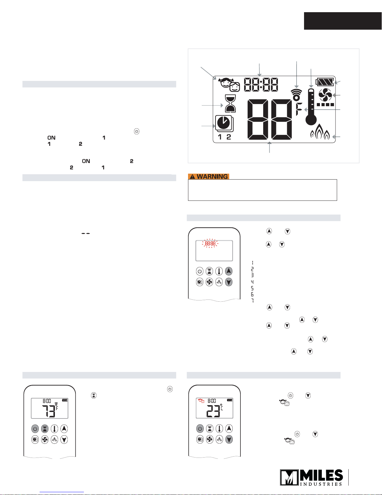
Child
Time
Signal Indicator
Proof
AM
PM
Countdown
Timer
Program
Mode
Handset Display
IMPORTANT: If the display on the handset indicates OFF,
it may not mean that the fire is off. Always check the fire
and pilot visually to ensure they are off.
nottub noitcnuf tnaveler eht sserp ,gni
SETTING THE TIME
SETTING THE TIME
-eD .etelpmoc si noitavitcaed litnu hsa À lliw noci noitcnuf ehT .3
ON
OFF
rof dloh dna nottub tna
-moc si noitavitca litnu hsa À ot eunitnoc lliw noci noitc
ON
OFF
Temperature
1. Press and buttons simultane-
AM
PM
ously. Day flashes.
2. Press or button to select a
number to correspond with the day
of the week.
= Monday
= Tuesday
= Wednesday
= Thursday
= Friday
= Saturday
= Sunday
3. Press and buttons simultaneously. Hour flashes.
4. To select hour press or button.
5. Press and buttons simultaneously. Minutes flash.
6. To select minutes press or
button.
7. To confirm press and buttons
simultaneously or wait.
Thermostatic Mode
Battery
Status
Fan
°F or °C
Eco
Mode
SETTI
NG CELSIUS OR FAHRENHEIT
SETTING CELSIUS OR FAHRENHEIT
To change between °C and °F, press
and
AM
PM
ON
OFF
buttons simultaneously.
NOTE: Choosing °F results in a 12 hour
clock. Choosing °C results in a
24 hour clock.
CHILD PROOF
CHILD PROOF
AM
PM
ON
OFF
ON:
To activ ate press
and but tons si multaneously. displayed and the
handset is rendered inoperable,
except for the OFF function.
OFF:
To d e a c ti v a te p re s s
and but tons
simultaneously. disappears.
11
OWNER’S
INFORMATION
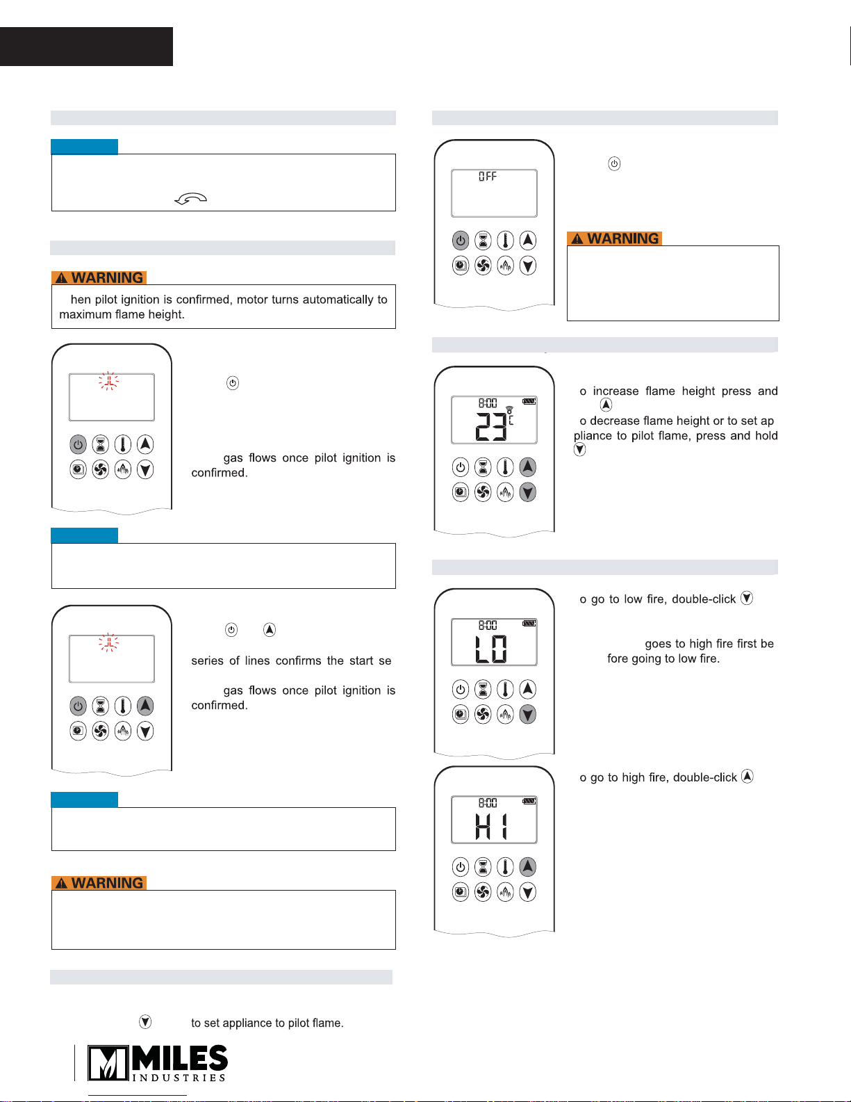
MANUAL MODE (HANDSET))
MANUAL MODE (HANDSET)
Remote Control Operation
TO TURN OFF FIRE
TO TURN OFF FIRE
NOTICE
BEFORE OPERATING
Make sure MANUAL knob on the GV60 Valve is in the ON,
full counterclockwise
TO TURN ON FIRE
TO TURN ON FIRE
position.
W
Handset One-Button Operation
AM
PM
ON
OFF
(Default Setting)
Press button and hold for four
ƒ
seconds until two short beeps and
a blinking series of lines confirms
the start sequence has begun;
release button.
ƒ Main
ƒ Handset automatically goes into man-
ual mode after main burner ignition.
NOTICE
To change from one-button to two-button ignition operation,
go to page 1 for instructions.
Handset
ƒ
AM
PM
ON
OFF
Press button and hold for four
seconds to turn OFF.
NOTE: There is a 5 sec delay before
the next ignition is possible.
IMPORTANT: If the display on the
handset indicates OFF, it may not
mean that the fire is off. Always
check the fire and pilot visually
to ensure they are off.
FLAME HEIGHT ADJUSTMENT
FLAME HEIGHT ADJUSTMENT
Handset
ƒ
AM
PM
ON
OFF
T
hold
button.
ƒ T -
button.
DESIGNATED LOW FIRE AND HIGH FIRE
DESIGNATED LOW FIRE AND HIGH FIRE
Handset Two-Button Operation
ƒ Press
AM
PM
ON
OFF
until two short beeps and a blinking
quence has begun; release buttons.
and button simultaneously
ƒ Main
ƒ Handset automatically goes into man-
ual mode after main burner ignition.
NOTICE
To change from two-button to one-button ignition operation,
go to page 1 for instructions.
If the pilot does not stay lit after several tries, turn the gas control
knob to OFF (3) and call your local service technician or gas
OFF
supplier. See page 17 for more information.
STANDBY MODE (PILOT FLAME)
STANDBY MODE (PILOT FLAME)
ƒ T but-
AM
ton. “LO” is displayed.
NOTE: Flame
-
-
ƒ T but-
AM
ton. “HI” is displayed.
Handset
ƒ
Press and hold
button
12
Remote Control Operation
OWNER’S
INFORMATION
COUNTDOWN TIMER
COUNTDOWN TIMER
ON/SETTING:
Press and hold button until
AM
PM
ON
OFF
1.
displayed, and hour flashes.
2. To select hour press
3. T
button. Minutes
4. To select minutes press
ton.
5. T
button or wait.
OFF:
Press button, and countdown
time disapear.
NOTE:
At end of countdown time period, the fire turns off. The
CountdownTimer only works in Manual, Thermostatic, and
Eco Modes. Maximum countdown time is 9 hours and 50
minutes.
MODES OF OPERATION
MODES OF OPERATION
AM
PM
ON
OFF
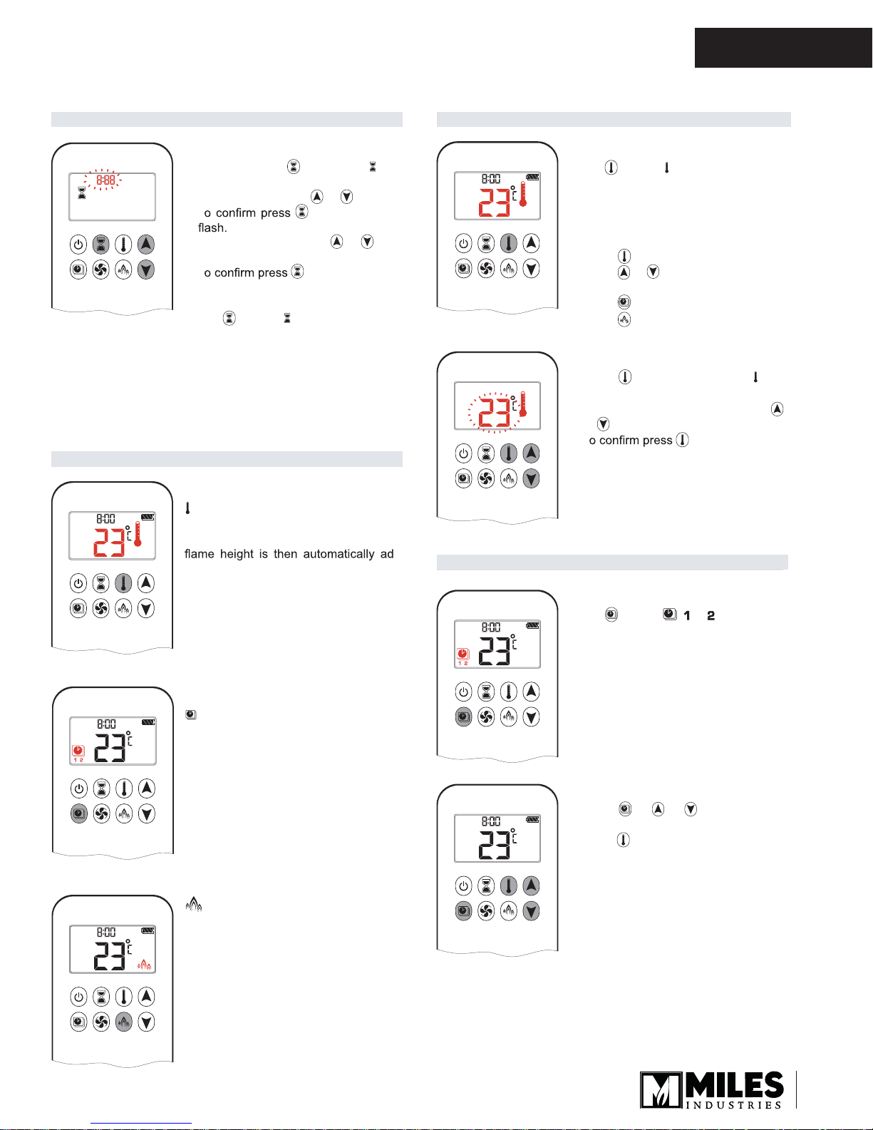
Thermostatic Mode
The room temperature is measured and
compared to the set temperature. The
justed to achieve the set temperature.
or button.
or but-
THERMOSTATIC MODE
THERMOSTATIC MODE
ON:
AM
PM
ON
OFF
Press button. displayed, preset
temperature displayed briefly, and then
room temperature displayed.
played.
OFF:
1. Press
2. Press
button.
or button to enter Manual
Mode.
3. Press button to enter Program Mode.
4. Press
button to enter Eco mode.
SETTING:
Press button and hold until dis-
AM
PM
ON
OFF
-
PROGRAM MODE
PROGRAM MODE
1.
played, temperature flashes.
2. To adjust SET temperature press
or
button.
3. T
button or wait.
ON:
AM
PM
ON
OFF
AM
PM
ON
OFF
Program Mode
Programs 1 and 2, each can be
programmed to go on and off at specific
times at a set temperature.
Press
displayed.
button. , or , ON or OFF
OFF:
AM
PM
ON
OFF
1. Press
Manual Mode.
2. Press
Mode.
or or button to enter
button to enter Thermostatic
Eco Mode
AM
Flame height modulates between high
and low. If the room temperature is
lower than the set temperature, the
flame height stays on high for a longer
period of time. If the room temperature
is higher than the set temperature, the
flame height stays on low for a longer
period of time. One cycle lasts approximately 20 minutes.
NOTE: The set temperature for Ther mostat ic Mode is th e tem -
perature for the ON time in Program Mode. Changing
the Thermostatic Mode set temperature also changes
the ON time temperature in Program Mode.
13
OWNER’S
INFORMATION
Remote Control Operation
Default settings:
ON TIME (Thermostatic) TEMPERATURE: 21°C (70°F)
OFF TIME TEMPERATURE: “ ” (pilot flame only)
TEMPERATURE SETTING:
AM
PM
ON
OFF
1. Press
ting in Thermostatic Mode) displayed.
2. To continue press button or wait.
button and hold until
.
and set temperature (set-
, displayed, temperature flashes.
3. Select off temperature by pressing
the
or button.
NOTE: The ON (Thermostatic) and OFF set temperatures are the
same for each day.
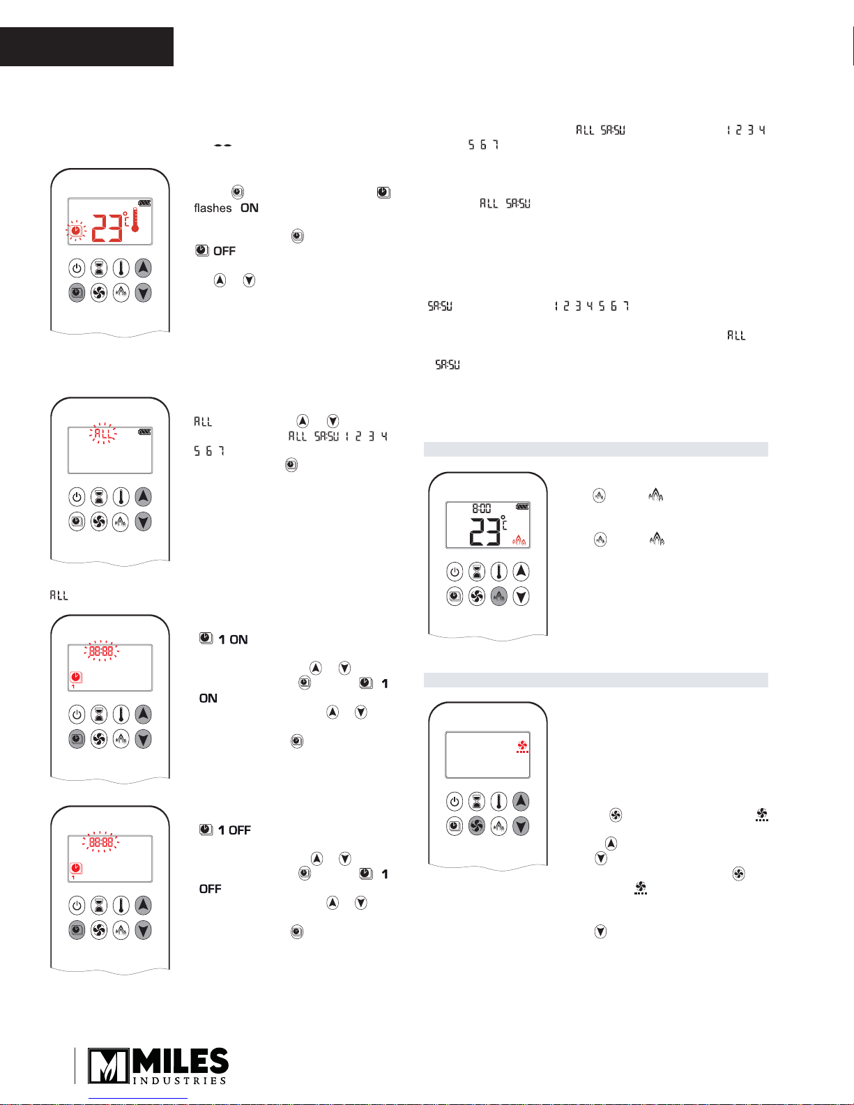
DAY SETTING:
4.
AM
PM
ON
OFF
À ashes. Press or button to
choose between
, , , , , ,
, , .
sserp mr ¿noc oT .5
button.
NOTE: PROGRAM 1 and 2 use the same on (Thermostatic) and
off temperatures for
, and “Daily Timer” ( , , , ,
, , ). Once a new on (Thermostatic) and/or off temper-
ature has been set, that temperature becomes the new
default setting.
NOTE: fI
, or “Daily Timer” are programmed for PROGRAM 1 and PROGRAM 2 on and off times, these become the new default times. The batteries must be removed to clear the PROGRAM 1 and PROGRAM 2 on
and off times and temperatures.
or “Daily Timer” ( , , , , , , ) selected
teS ƒ on time and off time using same procedure as “
se-
lected” (above).
ƒ
:
Set on time and off time for both Saturday and Sunday.
ƒUnique on and off times may be set for a single day of the week,
for multiple days of the week, or for every day of the week.
.gnittes hsin ¿ ot tiaW ƒ
ECO MODE
ECO MODE
ON:
AM
Press
button. displayed.
OFF:
Press
button. disappears.
selected
ON TIME SETTING (PROGRAM 1):
6.
AM
PM
ON
OFF
, , displayed, day is displayed
shortly, and hour À ashes.
sserp ruoh tceles oT .7
or button.
sserp mr ¿noc oT .8
button. , ,
displayed, minutes À ash.
sserp setunim tceles oT .9
or but-
ton.
10. To con¿ rm press
OFF TIME SETTING
AM
PM
ON
OFF
11. , , displayed, day is displayed
shortly, and hour À ashes.
button.
(PROGRAM 1):
sserp ,ruoh tceles oT .21
or button.
sserp mr ¿noc oT .31
button. , ,
displayed, minutes À ash.
sserp setunim tceles oT .41
or but-
ton.
15. T o con¿ rm press
button.
CIRCULATING FAN OPERATION
CIRCULATING FAN OPERATION
NOTE: SETTING only. Fan is switched
AM
on automatically when gas
opens. Circulating fan has 4
speed levels from low (1 bar) to
high (4 bars).
SETTING:
sserP .1
À ashes.
sserP .2
and
button to decrease fan speed.
ton or wait (
:FFO
sserP
button until all 4 speed level
bars disappear.
button and hold until
button to increase fan speed
sserp rehtie gnittes mr ¿noc oT .3
but-
displayed).
NOTE: Either continue to PROGRAM 2 and set on and off times
or
stop programming at this point, and PROGRAM 2 re-
mains deactivated.
14

Remote Control Operation
LOW BATTERY INDICATION
LOW BATTERY INDICATION
'RQRWXVHDVFUHZGULYHURURWKHUPHWDOOLFREMHFWWRUHPRYH
WKHEDWWHULHVIURPWKHUHFHLYHURUWKHKDQGVHW7KLVFRXOG
FDXVHDVKRUWFLUFXLWRIWKHUHPRWHFRQWUROV\VWHP
Handset
ƒ
7KHEDWWHU\LFRQZLOOVKRZZKHQWKHEDWWHU\QHHGVWREH
UHSODFHG5HPSODFHZLWKWZR9$$$alkaline EDWWHULHV
Receiver
ƒ
)UHTXHQWEHHSVIRUVHFRQGVZKHQWKHPRWRUWXUQVLQGLFDWH
WKHEDWWHULHVQHHGWREHUHSODFHG5HSODFHZLWKIRXU9
alkaline EDWWHULHV
AUTOMATIC TURN DOWN
AUTOMATIC TURN DOWN
3 Hour No Communication Function
ƒ
7KHYDOYHZLOOWXUQWRSLORWIODPHLIWKHUHLVQRFRPPXQLFDWLRQ
EHWZHHQKDQGVHWDQGUHFHLYHUIRUDKRXUSHULRG7KHILUHZLOO
FRQWLQXHWRIXQFWLRQQRUPDOO\ZKHQFRPPXQLFDWLRQLVUHVWRUHG
OWNER’S
INFORMATION
Receiver Overheating
RQO\LIRSWLRQDOFLUFXODWLQJIDQFRQWUROPRGXOHLVFRQQHFWHG
ƒ
9DOYHWXUQVWRSLORWIODPHLIWKHWHPSHUDWXUHLQWKHUHFHLYHULV
KLJKHUWKDQ°)°&7KHPDLQEXUQHUWXUQVEDFNRQ
PDQXDOO\RULQ7KHUPRVWDWLF0RGHRQO\ZKHQWKHWHPSHUDWXUH
LVEHORZ°)°&
AUTOMATIC SHUT OFF
AUTOMATIC SHUT OFF
Countdown Timer
ƒ
$WHQGRIFRXQWGRZQWLPHSHULRGWKHILUHWXUQVRII7KH
&RXQWGRZQ7LPHURQO\ZRUNVLQ0DQXDO7KHUPRVWDWLFDQG(FR
0RGHV0D[LPXPFRXQWGRZQWLPHLVKRXUVDQGPLQXWHV
Low Battery Receiver
:LWKORZEDWWHU\SRZHULQWKHUHFHLYHUWKHV\VWHPVKXWVRIIWKH
ƒ
ILUHFRPSOHWHO\7KLVZLOOQRWKDSSHQLIWKHSRZHUVXSSO\LV
LQWHUUXSWHG
Five Day Shut Off
7KHV\VWHPVKXWVRIIWKHILUHFRPSOHWHO\LIWKHUHLVQRFKDQJH
ƒ
LQIODPHKHLJKWIRUGD\V
15
OWNER’S
INFORMATION
Options
Required Kits
Fuel Beds (choose one)
1400DWK Driftwood Kit
1400DGM Murano Glass Kit
1400DGS Decorative Glass Set
1400LSK Traditional Log Kit
Liners (choose one)
1410VRL Valor Red Brick Liners
1415LSL Ledgestone Liners
1425FBL Fluted Black Liners
1460PBL Plain Black Liners
1470RGL
Surrounds (choose one) Barrier Screen Number
1430FFK Fixed Framing Kit
1435TSB Three-Sided Surround Black
1440FSB Four-Sided Surround Black
1440FSN Four-Sided Surround Nickel
1440FSZ Four-Sided Surround Bronze
Refl ective Glass Liners
4004587
Optional Accessories
Gas Conversion Kits
1400PGK From NG to LPG
1400NGK From LPG to NG
Other Accessories
1405RGL Refl ective Liner for 1425FBL or 1460PBL
1 156CLA Co-Linear Adapter
1195CFK Circulating Fan Kit
1265WSK Wall Switch Kit
1270RBK Remote Blower Kit
GV60PAK Power Kit
Hearth Gate
Hearth gates such as Cardinal’s VersaGates are available at retail stores carrying safety
products for children.
*Information accurate at the time of printing and subject to change without notice.
16
OWNER’S
Lighting Instructions
INFORMATION
FOR YOUR SAFETY, READ BEFORE LIGHTING
WARNING: If you do not follow these instructions exactly, a fi re or explosion may result
causing property damage, personal injury or loss of life.
A. This appliance has a pilot which must be lighted by hand, remote control, or wall switch. Follow these instructions
exactly. To save gas, turn the pilot off when not using the appliance for a prolonged period of time.
B. BEFORE LIGHTING, smell all around the appliance area for gas. Be sure to smell next to the fl oor because
some gases are heavier than air and will settle on the fl oor.
WHAT TO DO IF YOU SMELL GAS
• Do not try to light any appliance.
• Do not touch any electric switch; do not use any phone in your building.
• Immediately call your gas supplier from a neighbor’s phone. Follow the gas supplier’s instructions.
• If you cannot reach your gas supplier, call the fi re department.
C. Use only your hand to push in or turn the control knobs. Never use tools. If the knobs will not push in or turn by
hand, don’t try to repair them; call a qualifi ed service technician. Force or attempted repair may result in a fi re or
explosion.
D. Do not use this appliance if any part has been under water. Immediately call a qualifi ed service technician to
inspect the appliance and to replace any part of the control system and any gas control, which has been under water.
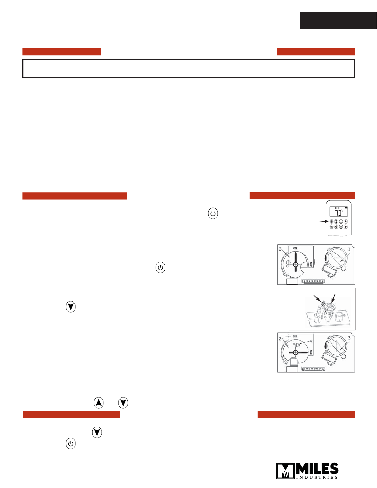
LIGHTING INSTRUCTIONS
1. STOP! Read the safety information above.
2. TO CLEAR ANY GAS, turn main valve off by pressing the button on remote handset (1).
• Wait fi ve (5) minutes to clear out any gas, then smell for gas, including near the fl oor. If you
smell gas, STOP! Follow “B” in the safety information above on this label. If you don’t smell
gas, go to the next step.
3. AUTOMATIC IGNITION: MAN-knob (2) in ON position. Ensure Flame Adjustment
knob (3) is set to lowest setting () (Fig. 1). Locate the pilot (Fig. 3.) inside the
fi rebox.
• On the remote control handset, press the button; a short acoustic signal
confi rms the start has begun.
• Further short acoustic signals indicate the ignition process is in progress.
• When the pilot is lit, the Flame Adjustment knob (3) will automatically rotate to
the highest setting.
• Press the button on the remote control handset to reduce the fl ame height.
Fig 3
4. MANUAL IGNITION: MAN-knob (2) in MAN position (Fig. 2). With the window
off, locate the pilot (Fig. 3) inside the fi rebox.
• Set Flame Adjustment knob (3) to the lowest setting ().
Pilot
• Push down the metallic core (4) with a pen or similar instrument; this will establish
the pilot gas fl ow.
• Light gas at the pilot (5) with a match.
• Continue holding down metal core (4) for about 10 seconds; after release, pilot
should remain lit.
• If the pilot will not stay lit after several tries, turn the gas control knob (3) to OFF () and call your local
service technician or gas supplier.
• Reinstall the window and set the MAN-knob (2) to ON; turn Flame Adjustment knob (3) up () or down ()
manually or use the and buttons on the remote control handset to adjust the fl ame height.
1
OFF
Spark
AM
Fig 1
5
Fig 2
AUTOMATIC SHUT-OFF (using the remote control handset):
• Press and hold the button on the remote control handset to shut-off the main burner gas fl ow.
• Press the button on remote handset to shut-off the appliance, including pilot fl ame.
TO TURN OFF GAS TO APPLIANCE
17

QUALIFIED
INSTALLER
Commonwealth of Massachusetts
State of Massachusetts Carbon Monoxide
Detector/Vent Terminal Signage
Requirements
For all side wall horizontally vented gas fueled
equipment installed in every dwelling, building or
structure used in whole or in part for residential
purposes, including those owned or operated by the
Commonwealth and where the side wall exhaust
vent termination is less than seven (7) feet above
fi nished grade in the area of the venting, including
but not limited to decks and porches, the following
requirements shall be satisfi ed:
1. INSTALLATION OF CARBON MONOXIDE
DETECTORS. At the time of installation of the side wall
horizontal vented gas fueled equipment, the installing
plumber or gas fi tter shall observe that a hard wired
carbon monoxide detector with an alarm and battery
back-up is installed on the fl oor level where the gas
equipment is to be installed. In addition, the installing
plumber or gas fi tter shall observe that a battery
operated or hard wired carbon monoxide detector
with an alarm is installed on each additional level of
the dwelling, building or structure served by the side
wall horizontal vented gas fueled equipment. It shall
be the responsibility of the property owner to secure
the services of qualifi ed licensed professionals for the
installation of hard wired carbon monoxide detectors.
3. SIGNAGE. A metal or plastic identifi cation plate
shall be permanently mounted to the exterior of the
building at a minimum height of eight (8) feet above
grade directly in line with the exhaust vent terminal for
the horizontally vented gas fueled heating appliance
or equipment. The sign shall read, in print size no less
than one-half (1/2) inch in size, “GAS VENT DIRECTLY
BELOW. KEEP CLEAR OF ALL OBSTRUCTIONS”.
4. INSPECTION. The state or local gas inspector of
the side wall horizontally vented gas fueled equipment
shall not approve the installation unless, upon
inspection, the inspector observes carbon monoxide
detectors and signage installed in accordance with the
provisions of 248 CMR 5.08(2)(a)1 through 4.
(b) EXEMPTIONS: The following equipment is exempt
from 248 CMR 5.08(2)(a)1 through 4:
1. The equipment listed in Chapter 10 entitled
“Equipment Not Required To Be Vented” in the most
current edition of NFPA 54 as adopted by the Board;
and
2. Product Approved side wall horizontally vented
gas fueled equipment installed in a room or structure
separate from the dwelling, building or structure used in
whole or in part for residential purposes.
a. In the event that the side wall horizontally vented
gas fueled equipment is installed in a crawl space or
an attic, the hard wired carbon monoxide detector with
alarm and battery back-up may be installed on the next
adjacent fl oor level.
b. In the event that the requirements of this subdivision
can not be met at the time of completion of installation,
the owner shall have a period of thirty (30) days
to comply with the above requirements; provided,
however, that during said thirty (30) day period, a
battery operated carbon monoxide detector with an
alarm shall be installed.
2. APPROVED CARBON MONOXIDE DETECTORS.
Each carbon monoxide detector as required in
accordance with the above provisions shall comply
with NFPA 720 and be ANSI/UL 2034 listed and IAS
certifi ed.
(c) MANUFACTURER REQUIREMENTS - GAS
EQUIPMENT VENTING SYSTEM PROVIDED.
When the manufacturer of Product Approved side
wall horizontally vented gas equipment provides a
venting system design or venting system components
with the equipment, the instructions provided by the
manufacturer for installation of the equipment and the
venting system shall include:
1. Detailed instructions for the installation of the venting
system design or the venting system components; and
2. A complete parts list for the venting system design or
venting system.
18

Commonwealth of Massachusetts
(d) MANUFACTURER REQUIREMENTS - GAS
EQUIPMENT VENTING SYSTEM NOT PROVIDED.
When the manufacturer of a Product Approved side
wall horizontally vented gas fueled equipment does
not provide the parts for venting the fl ue gases, but
identifi es “special venting systems”, the following
requirements shall be satisfi ed by the manufacturer:
1. The referenced “special venting system” instructions
shall be included with the appliance or equipment
installation instructions; and
2. The “special venting systems” shall be Product
Approved by the Board, and the instructions for that
system shall include a parts list and detailed installation
instructions.
(e) A copy of all installation instructions for all Product
Approved side wall horizontally vented gas fueled
equipment, all venting instructions, all parts lists
for venting instructions, and/or all venting design
instructions shall remain with the appliance or
equipment at the completion of the installation.
QUALIFIED
INSTALLER
19
QUALIFIED
INSTALLER
Specifi cations
Approval & Codes
This appliance is certifi ed to ANSI Z21.88-2014/
CSA 2.33-2014 American National Standard / CSA
Standard for Vented Gas Fireplace Heaters for use in
Canada and USA, and to CGA 2.17-91 High Altitude
Standard in Canada. This appliance is for direct vent
installations.
This appliance complies with CSA P4.1-09 Testing
method for measuring annual fi replace effi ciencies.
The installation must conform to local codes or, in the
absence of local codes, with the National Fuel Gas
Code, ANSI Z223.1 or the Natural Gas and Propane
Installation Code CAN/CGA-B149. Only qualifi ed
licensed or trained personnel should install this
appliance.
This appliance must be electrically grounded in
accordance with local codes, or, in the absence of local
codes, with the National Electrical Code, ANSI/NFPA
70 or the Canadian Electrical Code, CSA C22.1.
Ratings
Model 1400IN 1400IP
Gas Natural Propane
Altitude (Ft.)* 0-4,500 feet*
Input Maximum (Btu/h) 36,000 30,000
Input Minimum (Btu/h) 19,000 15,000
Manifold Pressure (in w.c.) 4.0” 9.0”
Minimum Supply Pressure (in w.c.) 5.0” 11.0
Maximum Supply Pressure (in w.c.) 10.0” 14.0
Main Burner Injector Marking 1000 360
Pilot Injector Marking 51 30
Min. Rate By-Pass Screw 220 125
*High Altitude Installations
Input ratings are shown in BTU
per hour and are certifi ed without
deration for elevations up to
4,500 feet (1,370 m) above sea
level.
For elevations above 4,500 feet
(1,370 m) in USA, installations
must be in accordance with the current ANSI Z223.1
and/or local codes having jurisdiction. Heating value
of gas in some areas is reduced to compensate for
elevation—consult your local gas utility to confi rm.
For installations at elevations above 4,500 feet
(1,370 m) in Canada, please consult provincial and/or
local authorities having jurisdiction.
X
Supply Gas
Heater engine 1400IN is used with natural gas.
Heater engine 1400IP is used with propane gas.
The supply pressure must be between the limits shown
in the Ratings section.
The supply connection is 3/8” NPT male and located on
the right hand side of the fi rebox. A shut-off valve (not
supplied) is required on the supply line to isolate the
unit during service. See Supply Gas Installation section
for details.
Conversion Kits
The 1400 is supplied as natural gas or propane gas
and is fi eld convertible between fuels. See instructions
packaged with the conversion kits for further
information.
Electrical
The 1400 is designed to run on battery power and does
not require an electrical power source to operate as a
heater. However, it requires electrical power to operate
optional 1195CFK Circulating Fan Kit, 1270RBK
Remote Blower Kit or GV60PAK Power Adapter.
20
S
ith Barrie
)
(
f
allow
Allothersurrounds
g
no
o
fi
fi
od
at
terial
ard.Formater
l
ty
y
ppag
g
8
Remote Handset
WaFh
ag
g
g
g
g
ggg
ggg
.
Wall Holder
rround w
Screen (required
Fixed Framing kit
1430FFK) installs at
raming stage and
s non-combustible
wall fi nish to fi nish up
to it.
overlap the surroundin
n-combustible wall
nish and are adjustable
accom
to 3/4” thickness
overtop of the base
2” non-combustible
e ma
QUALIFIED
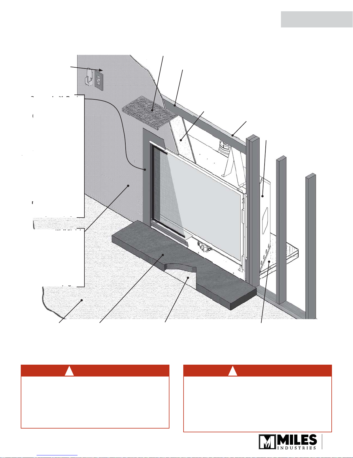
Overview
Mantel—See Mantel & Hearth Clearances
Framing—See Framing Requirements
1/2 inch thick noncombustible board
or equivalent –
r
NOT supplied—see
page 29 for board
specifi cations
Supplied as
vertical outlet, fi eld
convertible to
horizontal outlet.
1400 heater
INSTALLER
thickness greater than
4”, the heater requires
epositioningfurther
orward in the framing
avi
—see
Any wall fi nishes
lied over non-
ombustible board
ust be also
non-combustible.
ombustible mantels
re ok provided they
onform to chart
on
Combustible
Floor
e 4
e 23
Non-combustible Hearth—
See Hearth Requirements
1/2” Micore supplied
with unit. Use as a
thermal break between
non-combustible hearth
material and combustible
material underneath.
Combustible Framing Allowed Beneath Fireplace.
When the appliance is installed directly on
carpeting, tile or other combustible material other
than wood fl ooring, the appliance shall be installed
on a metal or wood panel extending the full width
and recessed depth of the appliance.
WARNING
!
Some materials or items, although safe,
may discolor, shrink, warp, crack, peel, and
so on because of the heat produced by the
fi replace. Avoid placing candles, paintings,
photos, and other items sensitive to heat
around the fi replace.
WARNING
!
HOT WALL SURFACES! The wall directly
above the fi replace is constructed of non-
combustible materials and, although safe, it
may reach temperatures in excess of 200° F
depending on choice of trims. Do not touch.
Finish the wall using materials suitable for
these temperatures.
21
(
)
f
(
)
d
ff
cal
uct
p
0
uct
t
)
e
t
ce
s
a
der
e
ing
e
o
t
t
d
r
t
t
e
ll
f
bustib
board.
)
”
/
”
)
/8
/
”
)
f
f
f
e
d
(
)
)
(
)
)
)
)
)
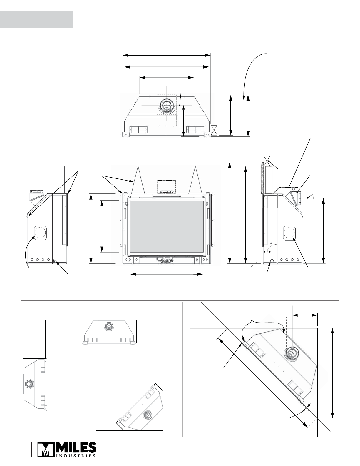
66-1/4” (1683 mm)
Face of framing
/8
”
QUALIFIED
INSTALLER
Dimensions & Location
Dimensions
Zero Clearan
nd-Off
877 mm
4-1/2”
5-1/2”
648 mm
3-7/8” (1115 mm
2-1/4” (1074 mm
7-3/8” (696 mm
Center
Top View
e: This dimension is for th
430FFK Fixed Framing Kit. For a
other trims this is the maximum
equired and may be reduced
if positioning the unit forward
of the framing to accomodate
thickness o
in
8
9-7
5-5
05 mm
8
20-3
518 mm
aterial over top of
ace o
r
ront
to
non-combustibl
n-com
non-combustible
e
le
Heat shiel
required fo
rear ven
outle
applications
6-5/8” dia.
Vent
ield-
nvertibl
from top t
rear outle
s
enter of ven
-o
1257 mm
cement board
1219 mm
8”
in.49-1/2”
o top o
-3/8
823 mm
2-3/8”
RBK D
127
Kit Inle
(remove plate
Electri
Inlet Point
Location
22
6-1/8” (918 mm
40 mm
Gas Lin
Access Poin
Front ViewLeft Side View Right Side View
Corner Dimensions
270RBK D
it Inlet
(remove
late)
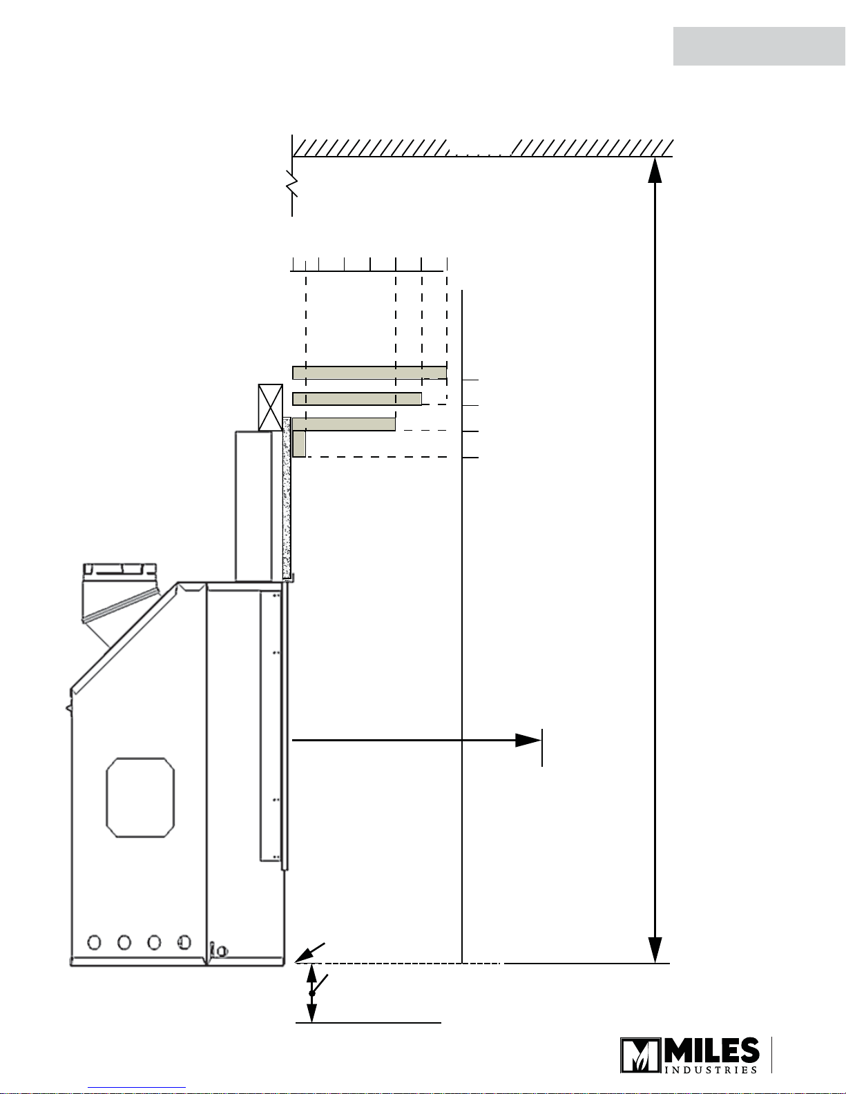
Mantel & Hearth Clearances
Combustible Mantel—Left Side View
Mantel Projection
(from Face of Cement Board)
02”1” 4” 6” 8” 10” 12”
Ceiling
52”
50”
48”
QUALIFIED
INSTALLER
Mantel
Height
(from
Bottom
of Unit)
Do not put
furniture or objects
within 36” (914 mm)
of front of appliance
46”
65” Min. to Ceiling
Bottom of Unit
4” minimum to combustible floor
or hearth. See Hearth Requirements
section of this manual.
23
 Loading...