

1265WSK
Control Wall Switch Kit
for Valor fi replaces equipped with GV60 valve
To be used only with Valor fi replaces
Installation & Operating Instructions
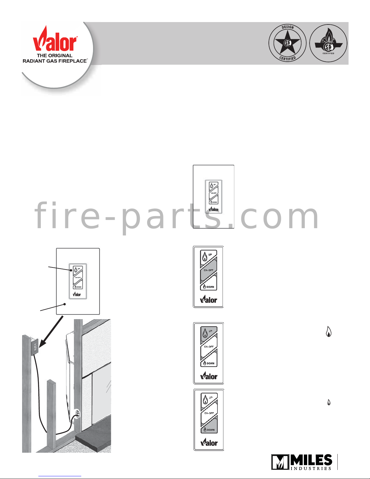
The optional Wall Switch Kit 1265WSK can be installed
to operate the fi replace. The kit includes the switch plate
and cover plate (available in white only) and a 26 feet
(8 m) long wiring harness. The wall switch allows to light
and turn the fl ame up or down but has no thermostat
or program features. The wall switch can be used in
conjunction with the thermostatic remote control.
All wiring associated with this kit is low voltage (6 volts).
Special considerations are required if ganging this
f i r e - p a r t s . c o m
switch with other switches of different voltage. Consult
your electrician.
Switch
plate
(white)
Cover
plate
(white)
Wall Switch Operation
The Wall Switch can be used to
control your fi replace. Y ou can
turn the pilot on or off and you can
increase or decrease the fl ame
height.
Note that the thermostat and
programming functions are not
available with the wall switch.
To turn appliance ON and OFF
• Press ON-OFF button once to light
pilot. Press again to shut of pilot.
To adjust fl ame height
• Press and hold large fl ame
button to gradually increase
fl ame height.
©2012, Miles Industries Ltd.
4001942-02
• Press and hold small fl ame
button to gradually decrease
fl ame height.
1
Installation
It is preferable to install the 1265WSK at the same time
as the fi replace. The kit is connected to the receiver in
the fi replace. The receiver is located near the control
valve under the burner module or on the left of the
fi rebox.
CAUTION
DO NOT PUT BATTERIES IN THE REMOTE
CONTROL RECEIVER until the wires are connected
to the burner control unit as short-circuit could result
in the destruction of the electrical components.
1. Decide where the switch is to be installed. Install
an electrical outlet box or mud ring as required (not
supplied).
2. Thread the switch wire through an access hole in
the appliance.
CAUTION
Do not run the switch wire over the top of the
fi rebox. Route the wire so it does not contact the
fi rebox.
f i r e - p a r t s . c o m
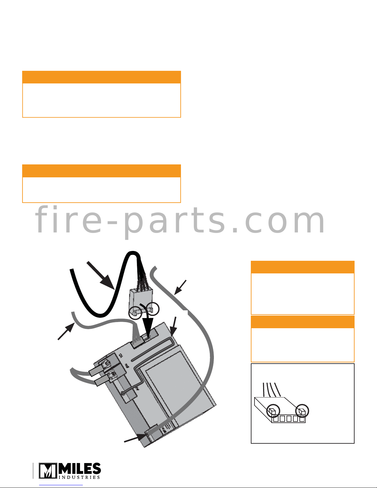
3. Pull out the receiver box. Remove the batteries from
the receiver box if it contains any. You can remove
the ignition wire to improve access to the receiver.
4. Take the switch wire and plug it into the receiver’s
connection slot as indicated (the other slot should
already be fi tted with the valve’s wire harness
connector). See diagrams below.
IMPORTANT: The connection can only be done
one way. Do not force it or damage the pins!
5. On the outside of the fi replace, run the switch wire
into the outlet box. Use insulated type staples to
secure the wiring to framing.
6. Plug the wire into the switch plate and to the outlet
box.
7. Reconnect the ignition wire to the receiver if it was
previously removed.
IMPORTANT: Make sure the ignition wire DOES
NOT TOUCH the receiver’s antenna.
8. Insert 4 AA alkaline batteries in the receiver.
Replace the cover.
9. Test the operation of the wall switch—see page 1.
10. Fix the wall cover plate to the outlet box.
11. Replace the receiver in its position and as well as
the antenna if deployed.
IMPORTANT: The antenna MUST NOT TOUCH
the ignition wire.
Wall Switch Harness
Valve Wire Harness
Ignition Wire Connection
(spade type connector)
Be careful when removing
and reinstallaing: not to bend or
break the spade connector
Ignition Wire
Antenna
CAUTION
DO NOT USE a screwdriver or
other metallic object to remove
the batteries from the receiver or
the handset! This could cause a
short circuit to the receiver.
CAUTION
To avoid short-circuit to the
receiver, position the antenna so
that it DOES NOT TOUCH the
ignition wire.
IMPORTANT: The connection
can only be done one way.
Do not force it or damage the
pins on the receiver box!
2
©2012, Miles Industries Ltd.
 Loading...