

Valor 1200EAN (NG), 1200EAP (LPG) Installation And Owner's Manual
VENTANA
Direct Vent ZC Fireplace
1200EAN (NG) & 1200EAP (LPG)
Installation & Owner’s Manual
INSTALLER
HOT GLASS WILL
CAUSE BURNS.
DO NOT TOUCH GLASS
UNTIL COOLED.
NEVER ALLOW CHILDREN
TO TOUCH GLASS.
WARNING: If the information in these
instructions is not followed exactly, a fi re
or explosion may result causing property
damage, personal injury or loss of life.
Do not store or use gasoline or other
fl ammable vapors and liquids in the vicinity
of this or any other appliance.
WHAT TO DO IF YOU SMELL GAS
• Do not try to light the appliance.
• Do not touch any electrical switch; do not
use any phone in your building.
• Immediately call your gas supplier from
a neighbor’s phone. Follow the gas
supplier’s instructions.
• If you cannot reach your gas supplier, call
the fi re department.
Installation and service must be performed
by a qualifi ed installer, service agency or the
gas supplier.
Leave this manual
with the appliance.
CONSUMER
Retain this manual
for future reference.
Please read this manual BEFORE installing
and operating this appliance.
This appliance may be installed in an
after-market permanently located,
manufactured (mobile) home where not
prohibited by local codes.
This appliance is only for use with the type
of gas indicated on the rating plate. This
appliance is not convertible for use with
other gases, unless a certifi ed kit is used.
This appliance is a domestic room-heating
appliance. It must not be used for any other
purposes such as drying clothes, etc.
This appliance is suitable for installation in a
bedroom or bed sitting room.
Massachusetts: The piping and fi nal
gas connection must be performed by a
licensed plumber or gas fi tter in the State of
Massachusetts. Also, see Carbon Monoxide
Detector requirements on page 16.
Ce guide est disponible en français sur demande.
MILES INDUSTRIES LTD., British Columbia, Canada
4001272-23
©2012, Miles Industries Ltd.
Manufactured by
www.valorfi replaces.com
W
A
R
R
A
N
T
Y
P
R
O
G
R
A
M
V
A
L
O
R
C
O
M
F
O
R
T
V
A
L
O
R
C
O
M
F
O
R
T
Table of Contents
FOR THE OWNER
Safety Precautions ............................................ 3
Safety and Your Fireplace .................................4
Owner’s Information .......................................... 5
Remote Control Operation...............................10
Options ............................................................14
Lighting Instructions.........................................15
Warranty ..........................................................48
FOR THE QUALIFIED INSTALLER
Warranty Card at the
back of this manual.
W
R
O
L
A
V
Y
T
N
A
R
R
A
C
O
M
M
A
R
G
O
R
P
T
R
O
F
Commonwealth of Massachusetts...................16
Specifi cations ..................................................18
Overview..........................................................19
Dimensions ...................................................... 20
Location ........................................................... 20
Mantel Clearances...........................................21
Hearth Requirements ...................................... 23
Framing ...........................................................26
Venting.............................................................27
Co-axial Venting .............................................. 28
Co-Linear Venting ............................................ 32
Installation Planning ........................................ 33
Appliance Preparation ..................................... 34
Supply Gas Installation .................................... 36
Ceramic Bricks Installation .............................. 38
Ceramic Logs Installation ................................ 39
Window Refi tting..............................................40
Remote Control Initial Set-up .......................... 41
Decorative Lighting Electrical Installation ........42
Operation Check & Aeration Settings
Adjustment.......................................................43
Window Skirt and Side Doors Installation........43
Remote Control Handset Wall Holder
Installation .......................................................44
Wiring Diagram ................................................ 45
Approved Venting Components ....................... 46
Warranty ..........................................................48
Spare Parts......................................................49
The information contained in this installation
manual is believed to be correct at the time of
printing. Miles Industries Ltd. reserves the right
to change or modify any information or specifi ca-
tions without notice. Miles Industries Ltd. grants
no warranty, implied or stated, for the installation
or maintenance of your heater, and assumes no
responsibility for any consequential damage(s).
190–2255 Dollarton Highway, North Vancouver, BC, CANADA V7H 3B1
2
Designed and Manufactured by / for
Miles Industries Ltd.
Tel. 604-984-3496 Fax 604-984-0246
www.valorfi replaces.com
© Copyright Miles Industries Ltd., 2012
Safety Precautions
!
READ and UNDERSTAND all instructions carefully
before starting the installation. FAILURE TO FOLLOW
these installation instructions may result in possible fi re
hazard and will void the warranty.
Prior to the fi rst fi ring of the fi replace, READ the
Owner’s Information section of this manual.
DO NOT USE this appliance if any part has been under
water. Immediately, CALL a qualifi ed service technician
to inspect the unit and to replace any part of the control
system and any gas control that has been under water.
THIS UNIT IS NOT FOR USE WITH SOLID FUEL.
Installation and repair should be PERFORMED by a
qualifi ed service person. The appliance and venting
system should be INSPECTED before initial use and at
least annually by a professional service person. More
frequent cleaning may be required due to excessive
lint from carpeting, bedding, etc. It is IMPERATIVE that
the unit’s control compartment, burner, and circulating
air passageways BE KEPT CLEAN to provide for
adequate combustion and ventilation air.
Always KEEP the appliance clear and free from
combustible materials, gasoline, and other fl ammable
vapors and liquids.
NEVER OBSTRUCT the fl ow of combustion and
ventilation air. Keep the front of the appliance CLEAR
of all obstacles and materials for servicing and proper
operation.
Due to the high temperature, the appliance should be
LOCATED out of traffi c areas and away from furniture
and draperies. Clothing or fl ammable material SHOULD
NOT BE PLACED on or near the appliance.
Clothing or fl ammable material SHOULD NOT BE
PLACED on or near the appliance.
Children and adults should be ALERTED to the hazards
of high surface temperature and should STAY AWAY to
avoid burns or clothing ignition.
YOUNG CHILDREN should be CAREFULLY
SUPERVISED when they are in the same room as
the appliance. Toddlers, young children and others
may be susceptible to ACCIDENTAL CONTACT
BURNS. A physical barrier is recommended if there
are at risk individuals in the house. To restrict access
to a fi replace or stove, INSTALL AN ADJUSTABLE
SAFETY GATE to keep toddlers, young children and
other at risk individuals out of the room and away from
hot surfaces.
This unit MUST be used with a vent system as
described in this installation manual. NO OTHER vent
system or components MAY BE USED.
This gas fi replace and vent assembly MUST be vented
directly to the outside and MUST NEVER be attached
to a chimney serving a separate solid fuel burning
appliance. Each gas appliance MUST USE a separate
vent system. Common vent systems are PROHIBITED.
INSPECT the external vent cap on a regular basis to
make sure that no debris, plants, trees, shrubs are
interfering with the air fl ow.
The glass door assembly MUST be in place and sealed
before the unit can be placed into safe operation.
DO NOT OPERATE this appliance with the glass door
removed, cracked, or broken. Replacement of the glass
door should be performed by a licensed or qualifi ed
service person. DO NOT strike or slam the glass door.
The glass door assembly SHALL ONLY be replaced
as a complete unit, as supplied by the fi replace
manufacturer. NO SUBSTITUTE material may be used.
DO NOT USE abrasive cleaners on the glass door
assembly. DO NOT ATTEMPT to clean the glass door
when it is hot.
TURN OFF the gas before servicing this appliance.
It is recommended that a qualifi ed service technician
perform an appliance check-up at the beginning of each
heating season.
Any safety screen or guard removed for servicing
MUST BE REPLACED prior to operating this appliance.
DO NOT place furniture or any other combustible
household objects within 36” of the fi replace front.
BE CAREFUL not to put any decorating objects
sensitive to heat to close above or around the fi replace
as it gets very hot when operating.
DO NOT use this heater as a temporary source of heat
during construction.
This appliance is a DOMESTIC ROOM-HEATING AP-
PLIANCE. It must not be used for any other purposes
such as drying clothes, etc.
State of California. Proposition 65 Warning. Fuels
used in gas, wood-burning or oil fi red appliances,
and the products of combustion of such fuels, contain
chemicals known to the State of California to cause
cancer, birth defects and other reproductive harm.
California Health & Safety Code Sec. 25249.6.
3
Safety and Your Fireplace
!
Safety and Your Fireplace
Please Read and Carefully Follow all Safety Warnings and
Operating Instructions Contained in Your Owners Manual
(Replacement Manuals are available by contacting our service department at
1-800-468-2567 or visit www.valorfi replaces.com).
Please Follow These Important
Child Safety Precautions and
Recommendations,
• Parts of your Valor Fireplace become
extremely hot while in operation.
• The glass viewing window
temperature can
exceed 500 F
at full capacity.
Momentary contact
with a hot glass
surface can cause
a severe burn, even if the fi replace
is operating at reduced heating
capacity.
withdraw in the event of accidental
contact with a hot surface.
• A physical barrier is strongly
recommended if there are young
children, or at-risk individuals in the
house. Install an approved aftermarket safety gate to keep toddlers,
young children and other at-risk
individuals a safe distance from the
fi replace.
• Keep the remote control handset
out of reach of children at all
times. A wall mount storage holster
is provided with your remote control
handset.
• The glass window will remain hot
for an extended period of time after
the fi replace has been turned off.
Ensure that children are prevented
from touching the fi replace during the
cool down period.
• Toddlers and Young Children
must be closely supervised at all
times when they are in the same
room as the operating fi replace. They
lack full awareness of danger and
rely on your protection. Toddlers,
in particular, do not have the motor
skills and response refl exes to
4
• Ensure that the fi replace, including
the pilot light, is completely turned
off when children are present and
close supervision and safety barriers
are not available—see page 9 of
Owner’s Information section.
• If the fi replace is not going to be used
for the summer or any extended
period of time, remove the batteries
from the remote control handset
and receiver. It is recommended that
batteries are replaced annually in any
event—see page 8.
Owner’s Information
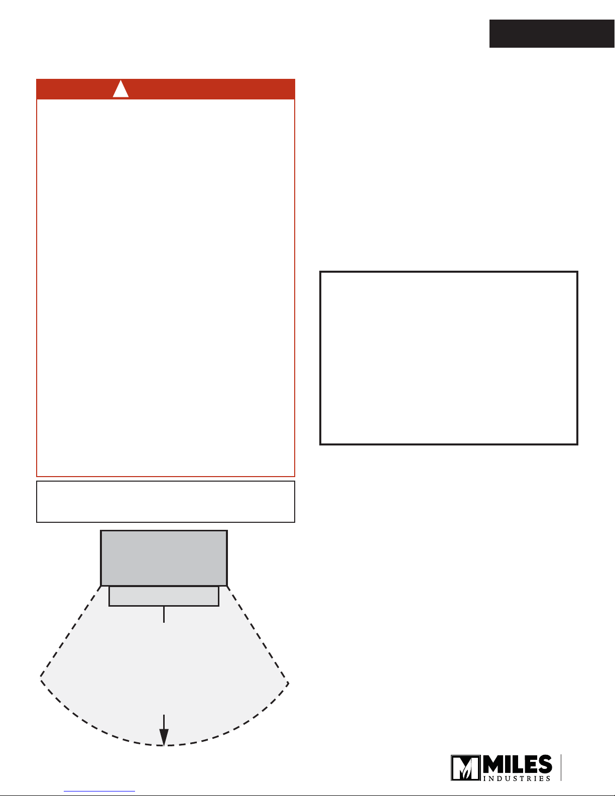
• • HOT HEARTH / FLOOR!
The hearth or fl oor
in front of the fi replace may become very hot
when the fi replace heats. Do not use the hearth
as a seat or shelf.
• • Some materials or items, although safe, may
discolor, shrink, warp, crack, peel, and so on
because of the heat produced by the fi replace.
AVOID PLACING
candles, paintings, photos,
and other items
SENSITIVE TO HEAT
• • Solid wood fl ooring in front of the fi replace (if
allowed) may shrink during the heating season
due to heat.
OWNER’S
INFORMATION
WARNING
!
EXTREMELY HOT!!!
• READ the SAFETY information on pages
3 and 4 of this manual BEFORE operating
your gas heater.
• Some parts of your fi replace are EXTREMELY
HOT, particularly the GLASS window.
• DO NOT LET CHILDREN touch the glass or
any parts of your fi replace even after it is
turned off as it is still hot.
• USE A SAFETY SCREEN or a GATE to reduce
the risk of severe burns.
• Keep the remote control handset OUT OF
REACH of children.
HOT HEARTH / FLOOR!
in front of the fi replace may become very hot
when the fi replace heats. Do not use the hearth
as a seat or shelf.
Some materials or items, although safe, may
discolor, shrink, warp, crack, peel, and so on
because of the heat produced by the fi replace.
AVOID PLACING
and other items
36 inches (0.9 m) around the fi replace.
Solid wood fl ooring in front of the fi replace (if
allowed) may shrink during the heating season
due to heat.
Performance of LPG appliances may be affected
by the quality of commercial gas supplied in
your area.
candles, paintings, photos,
SENSITIVE TO HEAT
The hearth or fl oor
within
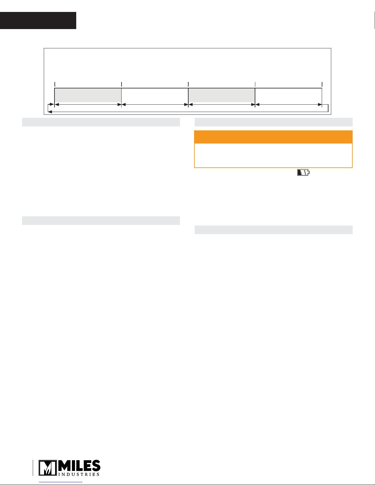
Fireplace
Hearth
Do not put
furniture or other objects
in this space in front of
the replace:
36” (0.9 m)
Thank You ...
For purchasing a Valor by Miles Industries. Your new
radiant gas heater is a technical appliance that must
be installed by a qualifi ed dealer. Each Valor fi replace
is fully tested during the production process for your
safety and comfort.
Your unit has been professionally installed by:
Dealer Name: ________________________________
Phone Number :_______________________________
Should you encounter an operational problem, call
your dealer immediately.
Do not try to repair the unit as you may cause an
injury or damage the fi replace.
This manual and particularly the preceeding
and following pages contain very important
information regarding the safe operation of your
fi replace as well as maintenance instructions.
Read carefully BEFORE operating your fi replace
and pay special attention to the SAFETY
WARNINGS.
A heating gas appliance does require safe handling
and for this reason, we very strongly recommend that
no children be allowed to touch the fi replace and its
controls at all times. Do install a screen or barrier
in front of the fi replace to protect your children
against severe burns.
Operating Your Fireplace for the First Time
When operating your new fi replace for the fi rst time,
some vapors may be released due to the burning of
curing compounds used in the manufacture of the
appliance. They may cause a slight odor and could
cause the fl ames to be the full height of the fi rebox, or
even slightly higher, for the fi rst few hours of operation.
It is also possible that these vapors could set off any
smoke detection alarms in the immediate vicinity.
These vapors are quite normal on new appliances. We
recommend opening a window to vent the room. After
a few hours use, the vapors will have disappeared and
the fl ames will be at their normal height.
Flame Supervision Device
For your safety, this appliance is fi tted with a fl ame
supervision device which will shut-off the gas supply
if, for any reason, the pilot fl ame goes out. This device
incorporates a fi xed probe, which senses the heat
from the pilot fl ame. If the probe is cool, the device will
prevent any gas fl ow unless manually lighting the pilot.
See full lighting instructions on page 15 of this manual.
5
DO NOT TOUCH THE GLASS WHILE IT IS HOT!
Let the fi replace cool fi rst before cleaning it.
OWNER’S
INFORMATION
Owner’s Information
Cleaning
WARNING
!
DO NOT TOUCH THE GLASS WHILE IT IS HOT!
Let the fi replace cool fi rst before cleaning it.
Important - Glass cleaning - Mineral deposits
One of the by-products of the combustion process in
a gas appliance is a mineral which can show up as a
white fi lm on the ceramic glass of the viewing door.
The composition of the deposit varies widely from
various locations and also from time to time in the same
location. It seems this is associated with the varying
sulfur content of the gas. You may have the problem for
a time and then not see it for many months when it will
reappear in your area.
We have discussed this problem with ceramic glass
manufacturers and they cannot give us a defi nitive
answer to this problem. Dealers have tried various
cleaning products with varying results. The following
recommendations will not guarantee results in your
particular case.
NOTE: This is a problem beyond Miles Industries’
control and is not covered under warranty.
• Clean the glass regularly as soon as you notice
the buildup (white fi lm). If the fi lm is left for a longer
period of time, it will bake on. It is then much harder,
if not impossible, to remove.
• NEVER use an abrasive cleaner on the ceramic
glass. Any abrasion of the surface has the
immediate effect of compromising the strength
of the glass. An emulsion type cleaner is
recommended.
• Use a soft damp cloth to apply the cleaner.
Dry the glass with a soft, dry, preferably
cotton cloth. Most paper towels and synthetic
materials are abrasive
to ceramic glass and should be avoided.
• Our dealers have had good results from the
products listed below. We cannot, however,
guarantee the results of these products.
» BRASSO, POLISH PLUS by KELKEM, COOK TOP
CLEAN CREME by ELCO, WHITE OFF by RUTLAND,
TURTLE WAX
Hot Glass Warning Plate
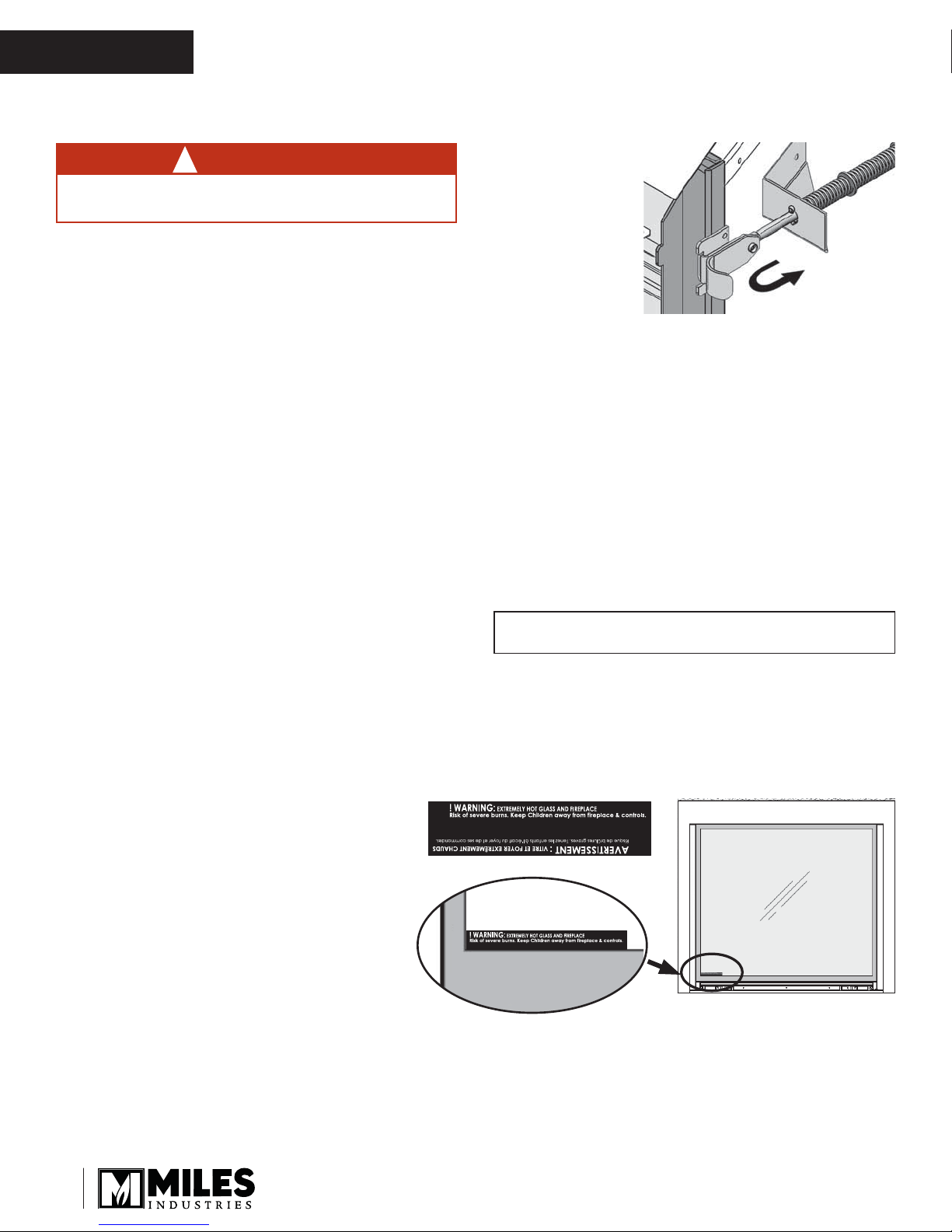
To remove the window for cleaning:
Spring Loaded
Window Levers
1. Find the levers on each side of the window towards
the top. Using your fi nger, pull the lever towards you
and unhook it from the window frame bracket.
2. Gently pull the top of the window outward.
3. Lift the window out of its bottom railing and set it
aside in a safe place to avoid damage.
To refi t the window:
1. Place it in its bottom railing and push its top against
the fi rebox.
2. While you hold it, pull the side levers back into the
window brackets on each side.
3. Pull out the top of the window and release it to
insure the springs return it.
IMPORTANT: To ensure a safe operation, ensure that
the spring-loaded mechanism functions properly.
4. Apply light hand pressure against the window frame
sides to bed-in the window seal.
5. If the Hot Glass Warning plate has been removed
from the front lower corner of the window,
reinstall it by sliding it between the glass and
the frame as indicated.
Do not clean the glass while it is hot. Always
securely replace the window before lighting. If broken,
the glass pane may only be replaced as a complete
window unit as supplied by the manufacturer.
6
Soot or dust can be brushed from the ceramic logs
and fi rebox walls using a soft brush. Dust can also
be removed from the burner using a soft brush after
removing the ceramic logs. When cleaning, make sure
that no particles are brushed into the slots of the burner.
Owner’s Information
OWNER’S
INFORMATION
Checks
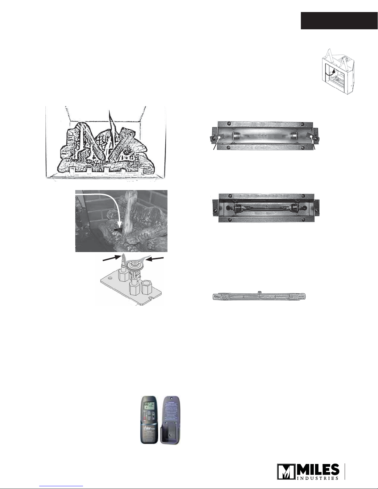
A periodic check of the pilot and burner fl ames should
be made. Check after the fi re has been on for at least
30 minutes. The pilot fl ame must cover the tip of the
thermocouple probe. The main burner fl ame pattern will
vary from appliance to appliance depending on the type
of installation and climatic conditions.
Correct Flame Picture
Pilot Flame
can be seen
between logs
Light Bulb Replacement
The appliance is equipped with a decorative light inside the fi rebox located in front
of the window. To replace the light bulb,
follow these steps:
1. Turn off the decorative light wall switch.
2. Locate the light fi xture. Loosen the screws of
the glass cover retaining tabs.
Ta b
Light fi xture with glass cover
3. While holding the glass cover so it does not fall
and shatter, swivel one or both of its retaining tabs
to free the glass. Gently remove the glass cover.
Light fi xture without glass cover
Ta b
Thermocouple
Probe must be
in Flame
Pilot
Flame
The appliance area must always be kept clear and
free from combustible materials, gasoline and other
fl ammable vapors and liquids.
Inspect the vent terminal outdoors regularly to make
sure that snow, trees, bushes, leaves, or other objects
do not obstruct it.
Examine the vent system and terminal regularly. We
recommend annually.
Remote Control Handset Wall Holder
Your fi replace equipment includes a wall
holder to store the handset. If it hasn’t
be installed, refer to the instructions
further on in this manual for the
installation.
4. Remove the light bulb from its socket by pushing
towards one end.
5. With a gloved hand, replace with a new light bulb
using a 100 watts halogen 130 volts (type J T3,
119 mm long).
100W Halogen Light Bulb (119mm)
6. Test the bulb by turning the wall switch on. Turn
the switch off again to complete the operation.
NOTE: If the bulb is new and not functioning, turn
off the dimmer switch and call your local electrician
for inspection.
7. Put the glass cover back in place and, while
holding it, turn the retaining tab(s) to retain
the glass.
8. Tighten the tabs’ screws.
7
OWNER’S
INFORMATION
Owner’s Information
Batteries
WARNING
!
DO NOT ATTEMPT TO CHANGE THE BATTERIES WHILE THE FIREPLACE IS STILL HOT! Let
the fi replace cool fi rst before touching it.
CAUTION
DO NOT USE a screwdriver or other metallic
object to remove the batteries from the receiver or
the handset! This could cause a short circuit to the
receiver.
Low battery signal: see page 14.
BEFORE changing the batteries, turn off the valve
using the manual On/Off switch —see instructions
next page.
The appliance uses four 1.5 V AA alkaline batteries
for its remote control receiver and one 9 V alkaline
battery for its handset. Batteries should last one to two
seasons, depending on usage. Removing the batteries
in the off-season will extend the battery life. Should
the batteries lose power, the control may be operated
by manually turning the control knob at the valve or by
turning off the valve at the switch.
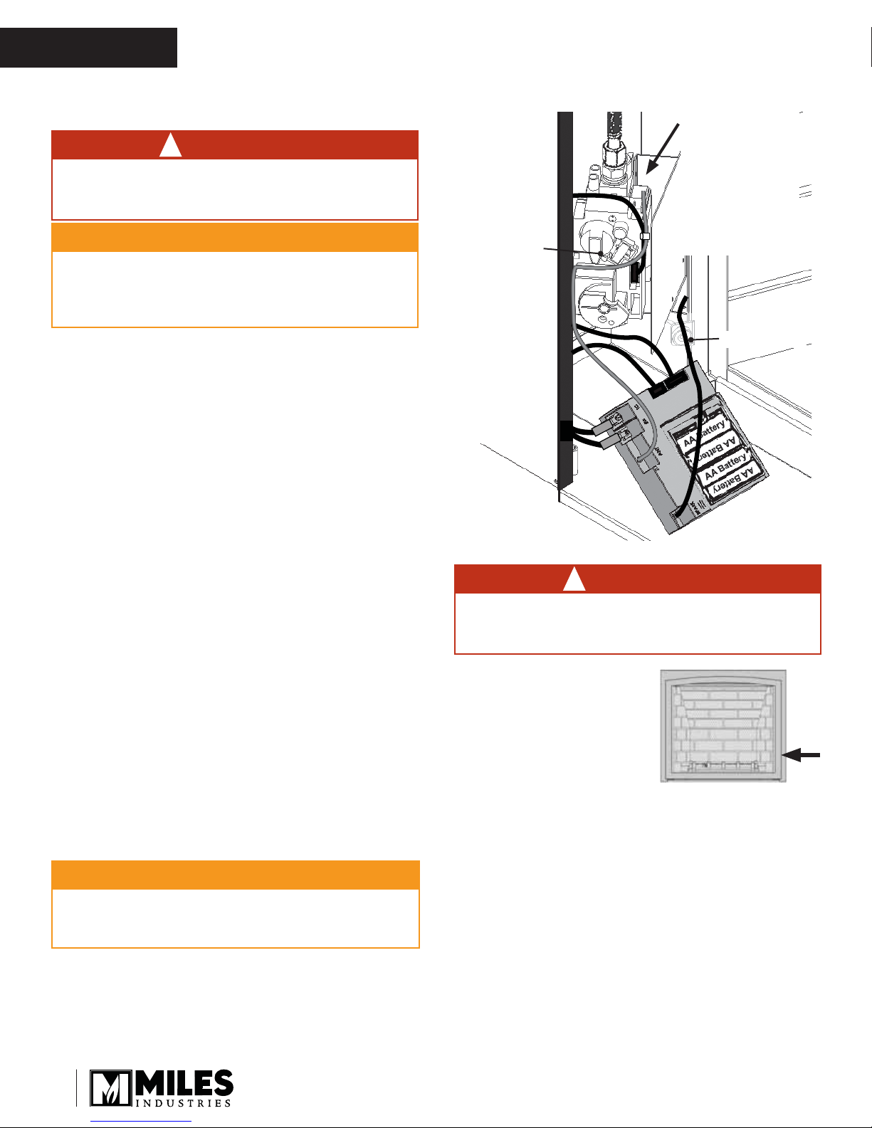
To replace the batteries in the remote control
receiver:
1. Open the side panel to the left of the window.
2. The receiver is located under the valve and it is
retained to its platform by a Velcro tab. Grab the
receiver and pull it out from it’s platform.
3. Slide and remove the receiver cover.
4. Replace the 4 AA batteries.
5. Replace the cover.
6. Put the receiver back on its platform pushing it in
so it attaches to the Velcro tab. If it was unhooked,
replace the antenna in its clip.
IMPORTANT: The antenna MUST NOT TOUCH
the ignition wire to avoid a short-circuit.
CAUTION
To avoid short-circuit to the receiver, position the
antenna so that it DOES NOT TOUCH the ignition
wire.
If the antenna was
unhooked when
replacing batteries,
hook it back to its
clip.
NOTE: It MUST
NOT TOUCH the
ignition wire!
Antenna
Ignition Wire
!
Lighting, Operation and Rating Information
WARNING
!
DO NOT ATTEMPT TO TOUCH THE DATA PLATE
WHILE THE FIREPLACE IS STILL HOT! Let the
fi replace cool fi rst before touching it.
The Lighting, Operation and
Rating information is located
on a plate at the right hand
side of the fi rebox behind the
side door.
To access the plate, open
the right hand side door and
grab the plate and slide it out
to read it. There is important
information on both sides of
the plate.
The data plate is
located on the right of
the fi rebox behind the
side door.
Servicing
If any attention is required for your appliance, contact
your supplier quoting the model number. It will be
helpful if the appliance serial number can also be
quoted. This number is on the rating plate, which is
located on the right hand side of the fi rebox behind
the side door. Open the side door and slide the plate
out. The replacement parts are shown at the end of
this manual. Please always quote the part number and
description when requesting spare parts.
8
Owner’s Information
OWNER’S
INFORMATION
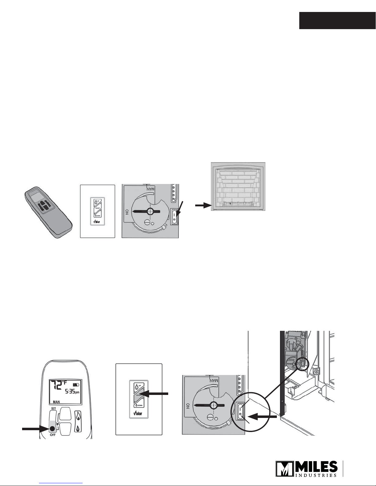
Fireplace Control Devices
There are three ways to control your fi replace.
1. Thermostatic Remote Control;
2. Wall Switch;
3. Manual On/Off Switch.
The manual On/Off switch must be ON for the fi replace
to function. It can be used to shut off the fi replace in
case of emergency—see above.
The Thermostatic Remote Control can be programmed
to function automatically—see pages 10–14.
The Wall Switch (optional) can be used to turn on, off
and to increase or decrease the fl ame height—see
1265WSK—Wall Switch Kit.
NOTE: The remote control in the AUTO mode will
override the wall switch.
Thermostatic Remote
Control
Wall Switch
(optional)
Manual On/Off Switch
How to Turn Your Fireplace OFF
(including pilot)
Familiarize yourself with each of these methods before
operating your fi replace.
How to Ensure Your Fireplace Cannot
Be Turned ON Inadvertently
You can use one of the two following methods to
ensure that your fi replace will not turn on when you
don’t want it on.
First, ensure your fi replace is turned off—including
the pilot—and cold BEFORE going ahead.
• You can prevent your fi replace from lighting by
pressing the O button on the manual ON/OFF
switch on the gas valve—see image at the bottom of
the page.
• Alternately, remove all batteries from the receiver as
well as the battery from the handset.
X
The receiver and gas
valve are located on
the left of the fi rebox
behind the side door.
Automatic Shut-Off (in certain conditions)
Your fi replace’s remote control is equipped with an
automatic shut-off mechanism which is activated in
certain conditions. See page 14 in the Remote Control
Operation section for a description of this feature.
Press and hold the OFF button for a second (either on
the handset or the wall switch).
If the fl ames are on, they go down and you hear the
valve motor wind down. You hear a clunk and a beep
indicating that the valve has received the signal from
the remote control.
Remote control
handset
Wall Switch
ON
OFF
Manual ON/OFF Switch
9
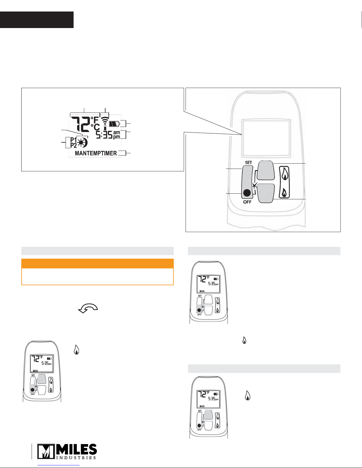
Current
temperature
(F or C)
Current time
(12 or 24 hour clock)
Modes (Manual,
Temperature, Timer)
Handset
sensor
Battery status
Current
programmed
period (Timer)
Period
start or end
(Temp, Timer)
OWNER’S
INFORMATION
Remote Control Operation
NOTE: Before using the remote control system for
the fi rst time, the receiver and the handset must be
synchronized. See the section Remote Control Initial
Set-up on page 41 of this manual.
Display Overview
Note: In the TEMP or TIMER modes, the remote
handset senses the room temperature and adjusts the
fl ame accordingly.
To communicate, the handset should be within 15 feet
(4.5 meters) of the fi replace.
Do not leave the handset on the mantel or hearth.
IMPORTANT: BEFORE YOU BEGIN, please note that
on this system, the settings of time, temperature and
automatic ON/OFF can only be programmed when
the function display is fl ashing. Be patient when
programming as it can take a few seconds to set.
Large ame
Set (scrolls
through
modes and
settings)
OFF (returns
to set mode,
turns the burner
and the pilot o)
Handset Overview
button (ames
up, sets hours,
temperature)
Small ame
button (ames
down and o,
sets minutes,
temperature)
TO TURN ON APPLIANCE TO TURN OFF APPLIANCE
CAUTION
When pilot ignition is confi rmed, motor turns
automatically to maximum fl ame height.
• On the valve, turn MAN knob on the ON, full
counterclockwise position.
• Place ON/OFF switch (if equipped) in I (ON
position).
• Simultaneously press the OFF and
(large fl ame) buttons until a short
beep confi rms the start sequence
has begun; release buttons.
• Continuing beeps confi rm the
ignition is in process.
• Once pilot ignition is confi rmed,
there is main gas fl ow.
• After main burner ignition the
10
handset will automatically go into
manual (MAN) mode.
• Press OFF button.
When the pilot is off, it will take 2
When the pilot is off, it will take 2
minutes before it can be lit again.
minutes before it can be lit again.
STANDBY MODE (Pilot Flame)
• Press and hold (small fl ame) to set appliance at
pilot fl ame.
FLAME HEIGHT ADJUSTMENT
• In standby mode: Press and hold
(large fl ame) button to increase
fl ame height.

Remote Control Operation
OWNER’S
INFORMATION
• Press and hold (small fl ame)
button to decrease fl ame height or
to set the appliance at pilot fl ame.
• For fi ne adjustment tap the
(large fl ame) or (small fl ame)
buttons.
Express Low and High Fire
• Double-click (small fl ame)
button. “LO” will be displayed.
NOTE: Flame goes to high fi re fi rst
before going to designated low fi re.
x 2
• Double-click (large fl ame)
button. Flame automatically goes
to high fi re. “HI” will be displayed.
x 2
SETTING ºC/24-HOUR OR ºF/12-HOUR CLOCK
• In MAN mode, press OFF and
(small fl ame) buttons until display
changes from Farenheit/12-hour
clock to Celsius/24-hour clock and
vice versa.
SETTING THE TIME
• The time display will fl ash after
either:
» Installing the battery or
» Simultaneously pressing the
(large fl ame) and (small
fl ame) buttons.
• Press (large fl ame) button to
set the hour.
• Press (small fl ame) button to
set the minute.
• Press OFF or simply wait to return
to MAN mode.
MODES OF OPERATION
• Briefl y pressing the SET button
changes the mode of operation in
the following order:
MAN
→ →
TIMER
→ → and back to .
TEMP
TEMP
MAN
NOTE: Manual mode can also be reached by pressing
either the (large fl ame) or the (small
fl ame) buttons.
MAN
• - Manual Mode - Manual
Flame Height Adjustment.
TEMP
• - Daytime Tempera-
ture Mode (Appliance must be in
standby mode; pilot ignited) - The
room temperature is measured and
compared to the set temperature.
The fl ame height is then auto-
matically adjusted to achieve the
Daytime Set Temperature.
TEMP
• - Nighttime Setback
Temperature Mode (Appliance
must be in standby mode; pilot
ignited) - The room temperature
is measured and compared to the
Nighttime Setback temperature.
The fl ame height is then automati-
cally adjusted to achieve the Nighttime Setback Temperature.
TIMER
• - Timer Mode (Appliance
must be in standby mode; pilot
ignited) - The timers P1 and P2
(Program 1, Program 2) each can
be programmed to go ON and OFF
at specifi c times. For instructions
see Timer Programming Mode.
NOTE: The display shows the set temperature every
30 seconds.
11
OWNER’S
INFORMATION
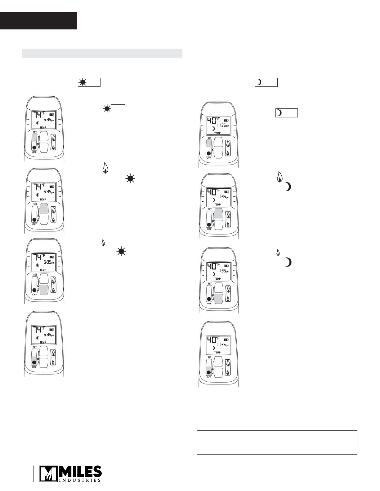
SETTING THE ON / OFF TEMPERATURES
SETTING THE “DAYTIME” TEMPERATURE
Default Settings: (sun), 23ºC / 74ºF
TEMP
Remote Control Operation
SETTING THE “NIGHTTIME SETBACK”
TEMPERATURE
Default Settings: (moon), “--” (OFF)
TEMP
• Briefl y press SET button to scroll to
TEMP (sun) mode. Hold
TEMP
the SET button until the TEMP
fl ashes.
• Press (large fl ame) button
to increase the Daytime Set
Temperature.
• Press (small fl ame) button
to decrease Daytime Set
Temperature.
• Briefl y press SET button to scroll to
TEMP (moon) mode. Hold
TEMP
the SET button until the TEMP
fl ashes.
• Press (large fl ame) button to
increase Nighttime Setback
Temperature.
• Press (small fl ame) button to
decrease Nighttime Setback
Temperature.
• Press OFF or simply wait to
complete programming.
12
• Press OFF or simply wait to
complete programming.
Tip
Set the different parameters when they are fl ashing.
Remote Control Operation
OWNER’S
INFORMATION
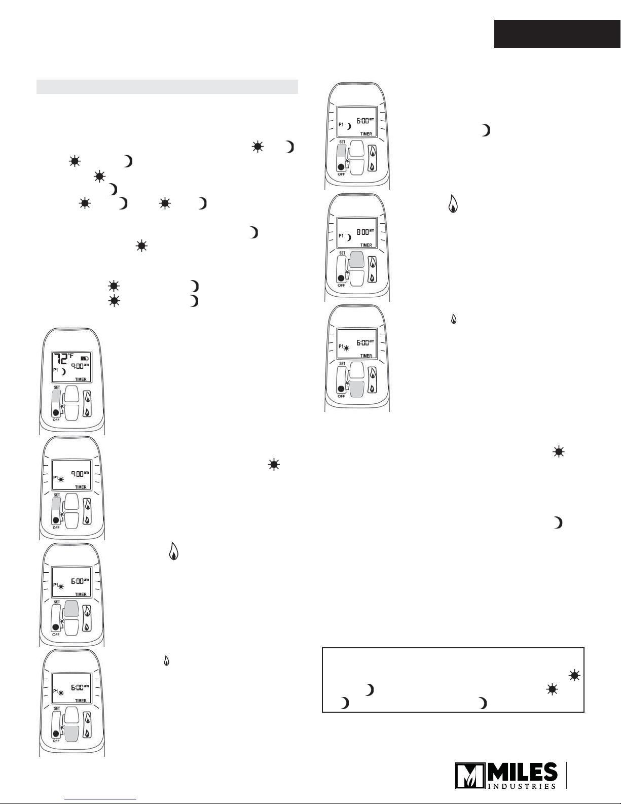
SETTING PROGRAM TIMERS
• You can program two periods of time between 12:00
am and 11:50 pm in each 24-hour cycle.
• The Programs P1 and P2 must be set in the
following order during a 24-hour cycle: , ,
P2
and .
• The icon indicates the beginning of the period (ON)
and the icon indicates the end of the period (OFF).
P1
• If = or = , the programming
is cancelled.
• To keep the fi replace ON all night, set at
11:50 am and at 12:00 am.
P1
P2
P1
P2
P2
P1
P2
P1
Default settings:
Program 1: 6:00 am 8:00 am
Program 2: 11:50 pm 11:50 pm
P1
P2
• Briefl y press SET button to scroll to
TIMER mode.
P1
P2
SETTING P1 OFF TIME
• Briefl y press SET button to scroll
to TIMER (moon) while the
time fl ashes.
• Press (large fl ame) button to set
the hour.
• Press (small fl ame) button to
set the minutes.
P1
SETTING P1 ON TIME
• Hold the SET button until
(sun) is displayed and the time
fl ashes.
• Press (large fl ame) button to
set the hour.
• Press (small fl ame) button to
set the minutes.
P1
SETTING P2 ON TIME
• Briefl y press SET to scroll to TIMER mode
(sun) while the time fl ashes.
• Follow the instructions given to set P1 ON time.
P2
SETTING P2 OFF TIME
• Briefl y press SET to scroll to TIMER mode
(moon) while the time fl ashes.
• Follow the instructions given to set P1 OFF time.
Press OFF button to save these settings. The timers
are programmed. See the diagram on programming
sequences on the following page.
P2
Tip
If you want to program only one period, program
and with desired times and program and
P1
P2
with the same time as .
P1
P1
P2
13
OWNER’S
INFORMATION
Timer Programming Example (default temperatures shown)
Remote Control Operation
6:00 a.m.—
P1
☼
Start time
Set temp 74˚F Set temp 40˚FSet temp 74˚F
AUTOMATIC TURN DOWN
• No communication. If there is no communication
between the receiver and the handset for a period of
6 hours, the appliance goes into pilot mode.
• No change in fl ame height. If there is no change
in fl ame height for a period of 6 hours, the appliance
goes into pilot mode.
NOTE: In TEMP or TIMER modes, the fl ame height
will vary according to room temperature. The appliance will continue to work normally. However, if the
room temperature remains the same for 6 hours, the
appliance will go into pilot mode.
AUTOMATIC SHUT OFF
• Low batteries in the receiver. With low battery
power in the receiver the system shuts off
completely.
NOTE: This does not apply when the power supply
is interrupted.
• No change in pilot. The appliance shuts off
completely when it is continually in pilot position—
without any change—for a period of 5 days.
☼
8:00 a.m.—
P1
☽
End time
Set temp 40˚F
☽☽
4:00 p.m.—
P2
☼
Start time
10:00 p.m.—
P2
☽
End time
6:00 a.m.—
P1
☼
Start time
☼
LOW BATTERY INDICATION
CAUTION
DO NOT USE a screwdriver or other metallic object
to remove the batteries from the battery box or the
handset! This could cause a short circuit.
Remote handset: The battery icon will show
when the battery needs to be replaced.
Replace with one 9 V alkaline battery.
Receiver: Three short ‘beeps’ will sound when the
motor turns when the batteries need to be replaced.
Replace with four 1.5 V alkaline batteries.
HANDSET / RECEIVER MATCH
The remote control handset and receiver are programmed to function together. In case of a replacement of
the handset or the receiver, you will need to reset the
receiver to allow them to function together. Contact your
dealer for details.
Ceramic Liners (required)
1245VRL—Victorian Red Liner Pack
1250FSL—Frontera Liner Pack
1255IBL—Inca Slab Liner Pack
1260BSL—Black Slab Liner Pack
Doors and Surrounds (optional)
1210DKA—Alhambra Door Kit
1215FDV—FenderFire Double Door Kit
1220FSV—FenderFire Single Door Kit
1240BPK—3-Sided Backing Plate Kit
1241FBK—4-Sided Backing Plate Kit
1235MTP—3-Sided Polished Trim
1237MFP—4-Sided Polished Trim
614CVI—Arched Cast Surround
615CVI—Cast Surround
Safety Screens (optional)
1205DSK—Draw Screen Kit
14
Options
Fret and Andirons (optional)
1225VFB—Ventana Fret Black
1230ACB—Andiron Classic Black
1236MAP—Metropolis Andiron Polished
Conversion Kit (optional)
1200PCK—Conversion Kit to Propane Gas
1200NCK—Conversion Kit to Natural Gas
Wall Switch (optional)
1265WSK—Wall Switch Kit
Fan (optional)
1270RBK—Remote Blower Kit
Hearth Gate (optional)
Hearth gates such as Cardinal VersaGates are
available at retail stores carrying safety products
for children.
X
OWNER’S
Lighting Instructions
INFORMATION
FOR YOUR SAFETY, READ BEFORE LIGHTING
WARNING: If you do not follow these instructions exactlyD¿UHRUH[SORVLRQPD\UHVXOWFDXVLQJ
SURSHUW\GDPDJHSHUVRQDOLQMXU\RUORVVRIOLIH
A. This appliance has a pilot which must be lighted by hand or by remote control. Follow these instructions exactly.To
save gas, turn the pilot off when not using the appliance for a prolonged period of time.
%%()25(/,*+7,1*VPHOODOODURXQGWKHDSSOLDQFHDUHDIRUJDV%HVXUHWRVPHOOQH[WWRWKHÁRRUEHFDXVHVRPHJDV
DUHKHDYLHUWKDQDLUDQGZLOOVHWWOHRQWKHÁRRr.
WHATTO DO IF YOU SMELL GAS
'RQRWWU\WROLJKWDQ\DSSOLDQFH
'RQRWWRXFKDQ\HOHFWULFVZLWFKGRQRWXVHDQ\SKRQHLQ\RXUEXLOGLQJ
,PPHGLDWHO\FDOO\RXUJDVVXSSOLHUIURPDQHLJKERr’s phone. Follow the gas supplier’s instructions.
,I\RXFDQQRWUHDFK\RXUJDVVXSSOLHrFDOOWKHÀUHGHSDUWPHQW
C. Use only your hand to push in or turn the control knobs. Never use tools. If the knobs will not push in or turn by hand,
GRQ·WWU\WRUHSDLUWKHPFDOODTXDOLÀHGVHUYLFHWHFKQLFLDQ)RUFHRUDWWHPSWHGUHSDLUPD\UHVXOWLQDÀUHRUH[SORVLRQ
D. Do not use this appliance if any part has been under water,PPHGLDWHO\FDOODTXDOLÀHGVHUYLce technician to inspect
the appliance and to replace any part of the control system and any gas control, which has been under water.
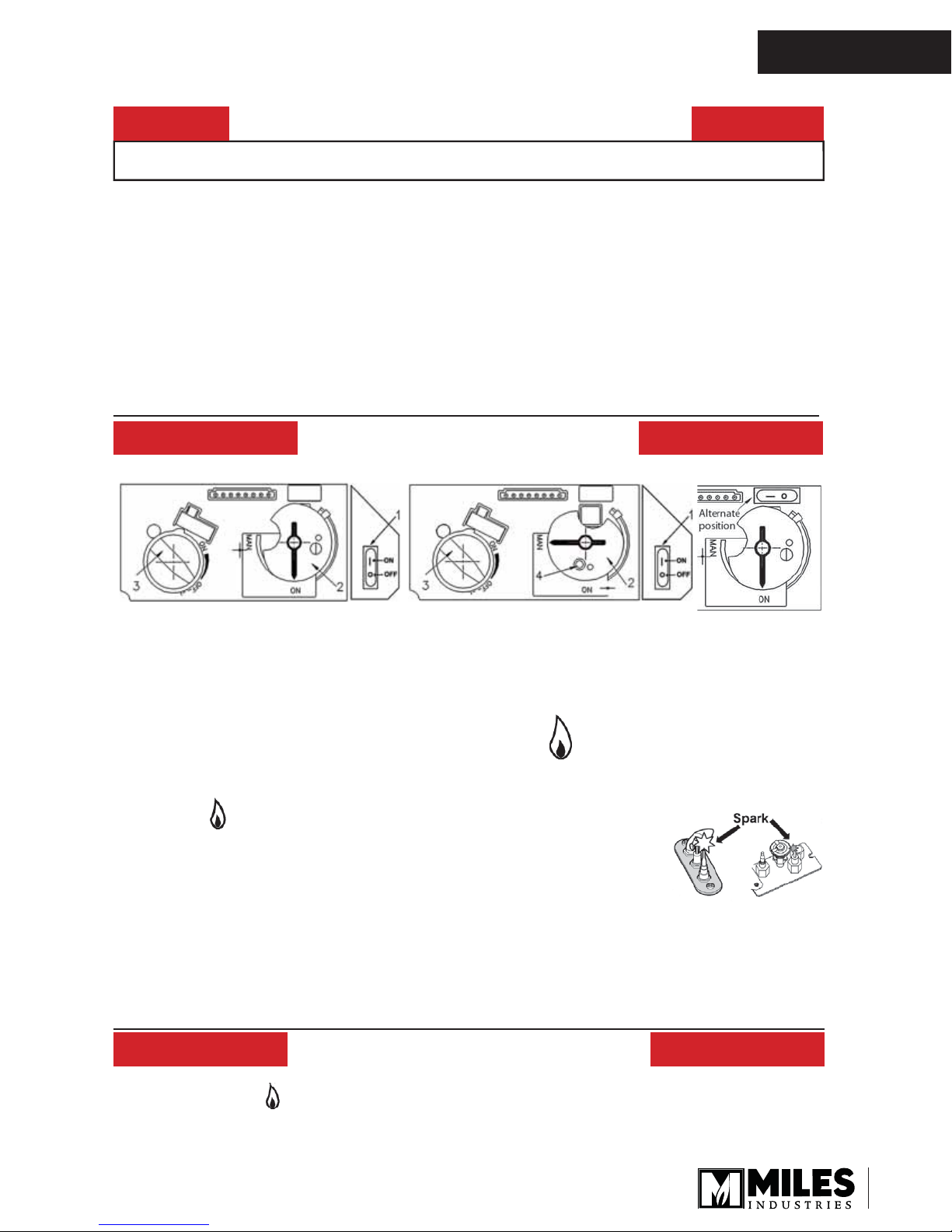
LIGHTING INSTRUCTIONS
1. STOP! Read the safety information above.Dependent on model, switch #1 may be mounted directly to valve see Fig 2A.
)LJ
2. SET ON/OFF SWITCH (1) TO “OFF” POSITION.
WDLWÀYHPLQXWHVWRFOHDURXWDQ\JDVWKHQVPHOOIRUJDVLQFOXGLQJQHDUWKHÁRRr. If you smell gas, STOP! Follow
“B” in the safety information above on this label. If you don’t smell gas, go to the next step.
3. AUTOMA7,&,*1,7,21ÀJ/RFDWHWKHSLORWÀJLQVLGHRIÀUHER[DW/HIW+DQGVLGH
212))VZLWFKLQ21SRVLWLRQ0$1NQRELQ21SRVLWLRQVHW)ODPH Adjustment knob (3) to lowest setting
(3);
On the remote control handset, press and hold the ‘off ’ button and (large flame) VLPXOWDQHRXVO\DVKRUW
DFRXVWLFVLJQDOFRQÀUPVWKHVWDUWKDVEHJXQ
)XUWKHUVKRUWDFRXVWLFVLJQDOVLQGLFDWHWKHLJQLWLRQSURFHVVLVLQSURJUHVV
When the pilot is lit, the Flame Adjustment knob (3) will automatically rotate to the highest setting.
Press the (small flame)RQWKHUHPRWHFRQWUROKDQGVHWWRUHGXFHWKHÁDPHKHLJKW
4. MANUAL,*1,7,21ÀJWLWKWKHZLQGRZRIIORFDWHWKHSLORWÀJ
LQVLGHRIÀUHER[DW/HIW+DQGVLGH
212))VZLWFKLQ21SRVLWLRQ0$1NQRELQ0$1SRVLWLRQ
Set Flame Adjustment knob (3) to the lowest setting (3);
3XVKGRZQWKHPHWDOOLFFRUHZLWKDSHQRUVLPLODULQVWUXPHQWWKLVZLOOHVWDEOLVKWKHSLORWJDVÁRZ
/LJKWJDVDWWKHSLORWZLWKDPDWFK
&RQWLQXHKROGLQJGRZQPHWDOFRUHIRUDERXWVHFRQGVDIWHUUHOHDVHSLORWVKRXOGUHPDLQOLW
5HLQVWDOOWKHZLQGRZDQGVHWWKH0$1NQREWR´21µWXUQ)ODPH Adjustment knob (3) up (4) or down
manually or use the up/down ‘flame’ buttons on the remote control handset to adjust theÁDPHKHLJKW
If the pilot will not stay lit after several tries, turn the gas control knob (3) to “OFF” (3) and call your local
service technician or gas supplier.
)LJ
)LJ$
TO TURN OFF GAS TO APPLIANCE
1. AUTOMATIC SHUT2))XVLQJWKHUHPRWHFRQWUROKDQGVHW
Press and hold the (small flame) RQWKHUHPRWHFRQWUROKDQGVHWWRVKXWRIIWKHPDLQEXUQHUJDVÁRZ
3UHVV´2))µEXWWRQRQUHPRWHKDQGVHWWRVKXWRIIWKHDSSOLDQFHLQFOXGLQJSLORWÁDPH
2. MANUAL SHUT-OFF (using only the ON/OFF switch (1))
Press “O” the ON/OFF switch (1) to shut-off the appliance.
)LJ
15

OWNER’S
INFORMATION
Commonwealth of Massachusetts
State of Massachusetts Carbon Monoxide
Detector/Vent Terminal Signage
Requirements
For all side wall horizontally vented gas fueled
equipment installed in every dwelling, building or
structure used in whole or in part for residential
purposes, including those owned or operated by the
Commonwealth and where the side wall exhaust
vent termination is less than seven (7) feet above
fi nished grade in the area of the venting, including
but not limited to decks and porches, the following
requirements shall be satisfi ed:
1. INSTALLATION OF CARBON MONOXIDE
DETECTORS. At the time of installation of the side wall
horizontal vented gas fueled equipment, the installing
plumber or gas fi tter shall observe that a hard wired
carbon monoxide detector with an alarm and battery
back-up is installed on the fl oor level where the gas
equipment is to be installed. In addition, the installing
plumber or gas fi tter shall observe that a battery
operated or hard wired carbon monoxide detector
with an alarm is installed on each additional level of
the dwelling, building or structure served by the side
wall horizontal vented gas fueled equipment. It shall
be the responsibility of the property owner to secure
the services of qualifi ed licensed professionals for the
installation of hard wired carbon monoxide detectors.
3. SIGNAGE. A metal or plastic identifi cation plate
shall be permanently mounted to the exterior of the
building at a minimum height of eight (8) feet above
grade directly in line with the exhaust vent terminal for
the horizontally vented gas fueled heating appliance
or equipment. The sign shall read, in print size no less
than one-half (1/2) inch in size, “GAS VENT DIRECTLY
BELOW. KEEP CLEAR OF ALL OBSTRUCTIONS”.
4. INSPECTION. The state or local gas inspector of
the side wall horizontally vented gas fueled equipment
shall not approve the installation unless, upon
inspection, the inspector observes carbon monoxide
detectors and signage installed in accordance with the
provisions of 248 CMR 5.08(2)(a)1 through 4.
(b) EXEMPTIONS: The following equipment is exempt
from 248 CMR 5.08(2)(a)1 through 4:
1. The equipment listed in Chapter 10 entitled
“Equipment Not Required To Be Vented” in the most
current edition of NFPA 54 as adopted by the Board;
and
2. Product Approved side wall horizontally vented
gas fueled equipment installed in a room or structure
separate from the dwelling, building or structure used in
whole or in part for residential purposes.
a. In the event that the side wall horizontally vented
gas fueled equipment is installed in a crawl space or
an attic, the hard wired carbon monoxide detector with
alarm and battery back-up may be installed on the next
adjacent fl oor level.
b. In the event that the requirements of this subdivision
can not be met at the time of completion of installation,
the owner shall have a period of thirty (30) days
to comply with the above requirements; provided,
however, that during said thirty (30) day period, a
battery operated carbon monoxide detector with an
alarm shall be installed.
2. APPROVED CARBON MONOXIDE DETECTORS.
Each carbon monoxide detector as required in
accordance with the above provisions shall comply
with NFPA 720 and be ANSI/UL 2034 listed and IAS
certifi ed.
(c) MANUFACTURER REQUIREMENTS - GAS
EQUIPMENT VENTING SYSTEM PROVIDED.
When the manufacturer of Product Approved side
wall horizontally vented gas equipment provides a
venting system design or venting system components
with the equipment, the instructions provided by the
manufacturer for installation of the equipment and the
venting system shall include:
1. Detailed instructions for the installation of the venting
system design or the venting system components; and
2. A complete parts list for the venting system design or
venting system.
16

Commonwealth of Massachusetts
(d) MANUFACTURER REQUIREMENTS - GAS
EQUIPMENT VENTING SYSTEM NOT PROVIDED.
When the manufacturer of a Product Approved side
wall horizontally vented gas fueled equipment does
not provide the parts for venting the fl ue gases, but
identifi es “special venting systems”, the following
requirements shall be satisfi ed by the manufacturer:
1. The referenced “special venting system” instructions
shall be included with the appliance or equipment
installation instructions; and
2. The “special venting systems” shall be Product
Approved by the Board, and the instructions for that
system shall include a parts list and detailed installation
instructions.
(e) A copy of all installation instructions for all Product
Approved side wall horizontally vented gas fueled
equipment, all venting instructions, all parts lists
for venting instructions, and/or all venting design
instructions shall remain with the appliance or
equipment at the completion of the installation.
OWNER’S
INFORMATION
17
 Loading...