


INC.
FARM EQUIPMENT MANUFACTURER
ROUND BALE GRINDER
MODEL H
OPERATOR'S MANUAL
AND PARTS BOOK

VALMETAL INC.
SHREDDER
WARRANTY
Valmetal Incorporated (Valmetal) warrants a new SHREDDER to be free from defects in material and workmanship,
under normal use and service. Obligation under this warranty shall extend for a period of 1 year (12 months) following the date of delivery to the original purchaser and shall be limited to replacement or repair at Valmetal’s choice of
any parts found to be defective upon inspection by Valmetal.
WARRANTY CLAIMS
The purchaser claiming under this warranty shall submit a warranty claim in the prescribed form to Valmetal or an
Authorized Dealer, for inspection by an authorized company representative.
LIMITATIONS OF LIABILITY
This warranty is expressly in lieu of all other warranties expressed or implied and all other obligations or liabilities on
Valmetal’s part of any kind or character, including liabilities for alleged representations or negligence. We neither
assume nor authorize any other person to assume on our behalf, any liability in connection with the subsequent sale
of the SHREDDER.
This warranty shall not apply to any SHREDDER which has been altered outside the factory in any way if, according
to Valmetal, the alterations affected the SHREDDER’s operation and reliability, or if the SHREDDER has been subject to misuse or accident.
This warranty does not apply to parts that are under warranty by the original manufacturer and for which service can
be obtained directly through authorized service centers. No warranty is extended to regular service items such as
lubricants, belts, paint and the like.
OPERATOR’S MANUAL
The Purchaser acknowledges having received training on safe operation of the SHREDDER and further acknowledges that Valmetal does not assume any liability resulting from the operation of the SHREDDER in any manner
other than described in the Operator’s Manual supplied at the time of purchase.
INSPECTION PROCEDURE
Wheel bolts tight
Fasteners tight
Chains adjusted
Belts adjusted
Hydraulic fittings tight
Knives in good condition
All drives turn freely
Check tire pressures
Lubricate machine
All safety decals installed
Reflectors, lights and SMV clean
Guards and shields installed and secured
Review operating and safety instructions with customer
WARRANTY VOID IF NOT REGISTERED

SERIAL NUMBER LOCATION
Always state the serial number of your Valmetal Round Bale Grinder when ordering parts or requesting
service or other information.
The serial number plate is located where indicated. Please mark the number in the space provided for
easy reference.
MODEL TYPE:
SERIAL NUMBER:

Contents
SECTION 1 INTRODUCTION....................................................................................
SECTION 2
SAFETY.............................................................................................................................
2.1 GENERAL SAFETY.......................................................................................................................
2.2 OPERATING SAFETY...................................................................................................................
2.3 MAINTENANCE SAFETY..............................................................................................................
2.4 HYDRAULIC SAFETY....................................................................................................................
2.5 TRANSPORT SAFETY..................................................................................................................
2.6 STORAGE SAFETY.......................................................................................................................
2.7 TIRE SAFETY................................................................................................................................
2.8 SAFETY DECALS..........................................................................................................................
2.9 SIGN-OFF FROM...........................................................................................................................
SECTION 3 SAFETY DECAL LOCATIONS...............................................................
SECTION 4 OPERATION.........................................................................................
4.1 TO THE NEW OPERATOR OR OWNER......................................................................................
4.2 MACHINE COMPONENTS............................................................................................................
4.3 BREAK-IN......................................................................................................................................
4.4 PRE-OPERATION CHECKLIST....................................................................................................
4.5 EQUIPMENT MATCHING.............................................................................................................
4.6 CONTROLS...................................................................................................................................
4.7 ATTACHING / UNHOOKING MACHINE.......................................................................................
4.8 OPERATING..................................................................................................................................
4.9 TRANSPORTING..........................................................................................................................
4.10 STORAGE.....................................................................................................................................
SECTION 5 SERVICE AND MAINTENANCE...........................................................
5.1 SERVICE.......................................................................................................................................
5.1.1 FLUIDS AND LUBRICANTS................................................................................................................
5.1.2 GREASING.........................................................................................................................................
5.1.3 SERVICING INTERVALS...................................................................................................................
5.1.4 SERVICE RECORD...........................................................................................................................
5.2 MAINTENANCE.............................................................................................................................
5.2.1 SECTION REPLACEMENT................................................................................................................
5.2.2 BELT AND ROLLER CHAINS............................................................................................................
5.2.3 GEARBOX OIL...................................................................................................................................
5.2.4 BREATHER CLEANING.....................................................................................................................
5.2.5 SLIP CLUTCH MAINTENANCE.........................................................................................................
SECTION 6 TROUBLE SHOOTING...........................................................................
SECTION 7
SPECIFICATIONS.............................................................................................................
7.1 MECHANICAL...............................................................................................................................
7.2 BOLT TORQUE.............................................................................................................................
7.3 HYDRAULIC FITTING TORQUE...................................................................................................
7.4 HYDRAULIC CIRCUIT...................................................................................................................
Page
1
2
3
4
4
5
5
6
6
6
7
8
9
13
13
14
15
16
17
18
19
21
28
29
31
31
31
31
32
36
37
37
38
39
40
41
43
45
46
47
48
48

SECTION 1 INTRODUCTION
Congratulations on your choice of a ValMetal Round Bale Grinder to complement your farming operation.
This equipment has been designed and manufactured to meet the needs of a discriminating buyer for the efficient grinding of large round bales.
Safe, efficient and trouble free operation of your ValMetal Round Bale Grinder requires that you and anyone
else who will be operating or maintaining the Grinder, read and understand the Safety, Operation,
Maintenance and Trouble Shooting information contained in the Operator's Manual.
This manual covers the Model H Grinder manufactured by ValMetal.
Keep this manual handy for frequent reference and to pass on to new operators or owners. Call your
ValMetal Dealer or Distributor if you need assistance or information.
OPERATOR ORIENTATION - The directions left, right, front and rear, as mentioned throughout this manual,
are as seen from behind the tractor driver's seat and facing in the direction of travel.
SAFETY
1

2

SAFETY
3
SECTION 2 SAFETY
SAFETY ALERT SYMBOL
This Safety Alert symbol means
ATTENTION! BECOME ALERT!
YOUR SAFETY IS INVOLVED!
SIGNAL WORDS:
The Safety Alert symbol identifies important
safety messages on the ValMetal Round Bale
Grinder and in the manual. When you see this
symbol, be alert to the possibility of personal
injury or death. Follow the instructions in the
safety message.
Why is SAFETY important to you ?
3 Big Reasons
Accidents Disable and Kill
Accidents Cost
Accidents Can be avoided
Note the use of the signal words DANGER,
WARNING and CAUTION with the safety
messages. The appropriate signal word for
each message has been selected using the
following guide-lines:
DANGER -
WARNING -
CAUTION -
An immediate and specific hazard
which WILL result in severe personal
injury or death if the proper precautions are not taken.
A specific hazard or unsafe practice
which COULD result in severe personal injury or death if proper precautions are not taken.
Unsafe practices which COULD
result in personal injury if proper
practices are not taken, or as a
reminder of good safety practices.

SAFETY
YOU are responsible for the SAFE operation and
maintenance of your ValMetal Round Bale Grinder.
YOU must ensure that you and anyone else who is
going to operate, maintain or work around the
Grinder be familiar with the operating and maintenance procedures and related SAFETY information
contained in this manual. This manual will take you
step-by-step through your working day and alerts you
to all good safety practices that should be adhered to
while operating the Grinder.
Remember, YOU are the key to safety. Good safety
practices not only protect you but also the people
around you. Make these practices a working part of
your safety program. Be certain that EVERYONE
operating this equipment is familiar with the recommended operating and maintenance procedures and
follows all the safety precautions. Most accidents
can be prevented. Do not risk injury or death by
ignoring good safety practices.
Grinder owners must give operating instructions to
operators or employees before allowing them to
operate the Grinder, and at least annually thereafter
per OSHA regulation 1928.57.
The most important safety device on this equipment
is a SAFE operator. It is the operator's responsibility
to read and understand ALL Safety and Operating
instructions in the manual and to follow these. All
accidents can be avoided.
A person who has not read and understood all operating and safety instructions is not qualified to operate the machine. An untrained operator exposes
himself and bystanders to possible serious injury or
death.
Do not modify the equipment in any way.
Unauthorized modification may impair the function
and/or safety and could affect the Iife of the equipment.
Think SAFETY! Work SAFELY!
2.1 GENERAL SAFETY
1 . Read and understand the Operator's Manual and
all safety signs before operating, maintaining or
adjusting the Grinder.
2. Have a first-aid kit available for
use should the need arise and
know how to use it.
3. Have a fire extinguisher
available for use should
the need arise and know
how to use it.
4. Wear appropriate protective gear. This list
includes but is not limited to:
- A hard hat
- Protective shoes with slip resistant soles
- Protective glasses or goggles
- Heavy gloves
- Hearing protection
5. Install and secure all guards before starting.
6. Wear appropriate ear
protection for prolonged
exposure to excessive
noise.
7. Raise grate, place all controls in neutral, stop
engine, set park brake, remove ignition key and
wait for all moving parts to stop before servicing,
adjusting, repairing, unplugging or filling.
8. Clear the area of people, especially small children, before starting the unit.
9. Review safety related items annually with all
personnel who will be operating or maintaining
the Grinder.
SAFETY
4

2.2 OPERATING SAFETY
1. Read and understand the Operator's Manual and
all safety signs before operating, servicing,
adjusting, repairing, unplugging or filling.
2. Do not allow riders when transporting.
3. Do not go into tub when engine is running.
Keep others out.
4. Keep hands,feet,hair and clothing away from
moving parts.
5. Raise grate, place all controls in neutral, stop
engine, set park brake, remove ignition key and
wait for all moving parts to stop before servicing,
adjusting, repairing, unplugging or filling.
6. Place all tractor controls in neutral before
starting.
7. Clear the area of bystanders, especially small
children, before starting.
8. Do not point the discharge toward people or animals when operating. Objects can be thrown out
at a speed fast enough to seriously injure some
one or cause death. Stay away from discharge
path when operating. Keep others away.
9. Never operate machine with a cracked, bent,
missing or broken section.
10. Keep all hydraulic lines, fittings and couplers
tight and free of leaks before using.
11. Clean reflectors, SMV and lights before
transporting.
12. Install optional lighting bar and use pilot vehicle
when transporting during times of limited visibility.
13. Use hazard flashers on tractor when transporting.
14. Install safety chains when attaching to tractor.
15. Review safety instructions with all operators
annually.
2.3 MAINTENANCE SAFETY
1. Follow ALL the operating, maintenance and
safety information in the manual.
2. Support the machine with blocks or safety stands
when changing tires or working beneath it.
3. Raise grate, place all controls in neutral, stop
engine, set park brake, remove ignition key and
wait for all moving parts to stop before servicing,
adjusting, repairing or unplugging.
4. Follow good Shop Practices
- Keep service area
clean and dry.
- Be sure electrical
outlets and tools
are properly
grounded
- Use adequate light
for the job at hand
5. Make sure all guards are in place and properly
secured when maintenance work is completed.
6. Never wear ill-fitting,baggy or frayed clothing
when working around or on any of the drive
system components.
7. Before applying pressure to a hydraulic system,
make sure all lines, fittings and couplers are tight
and in good condition.
8. Relieve pressure from hydraulic circuit before
servicing or disconnecting from tractor.
9. Do not go into tub when engine is running.
Keep others out.
10. Keep hands, feet, hair and clothing away from
moving or rotating parts.
11. Clear the area of bystanders, especially small
children, when carrying out any maintenance
and repairs or making any adjustments.
SAFETY
5

2.4 HYDRAULIC SAFETY
1. Always place all tractor hydraulic controls in
neutral before dismounting.
2. Make sure that all components in the hydraulic
system are kept in good condition and are clean.
3. Replace any worn, cut, abraded, flattened or
crimped hoses and steel lines.
4. Do not attempt any makeshift repairs to the
hydraulic lines, fittings or hoses by using tape,
clamps or cements. The hydraulic system
operates under extremely high-pressure. Such
repairs will fail suddenly and create a hazardous
and unsafe condition.
5. Wear proper hand and
eye protection when
searching for a high
pressure hydraulic leak.
Use a piece of wood or
cardboard as a backstop
instead of hands to
isolate and identify a
leak.
6. If injured by a concentrated high-pressure stream
of hydraulic fluid, seek medical attention immediately. Serious infection or toxic reaction can
develop from hydraulic fluid piercing the skin
surface.
2.5 TRANSPORT SAFETY
1. Make sure you are in compliance with all local
regulations regarding transporting equipment on
public roads and highways.
2. Make sure that a Slow Moving Vehicle emblem
and all the lights and reflectors that are required
by the local highway and transport authorities are
in place, are clean and can be seen clearly by all
overtaking and oncoming traffic.
Note
: Emblem, lights and reflectors are to be
supplied by owner, if needed.
3. Do not allow anyone to ride on the machine
during transport.
4. Do not exceed 32 km/h (20 mph) when transporting the machine. Reduce speed on rough roads
and surfaces.
5. Use a tractor of 60 horsepower or more to
transport machine.
6. Install lighting bar before transporting.
7. Use a drawbar pin with provisions for a retainer.
Install the retainer.
8. Attach safety chain between tractor and machine
before transporting.
SAFETY
6
WA

2.6 STORAGE SAFETY
1. Store the Grinder in an area away from human
activity.
2. Do not permit children to play on or around the
stored machine.
3. Make sure the unit is sitting, or blocked up firm
and solid and will not tip or sink into a soft area.
4. Cover with a weather-proof tarpaulin and tie
down securely.
2.7 TIRE SAFETY
1. Failure to follow proper procedures when mounting a tire on a wheel or rim can produce an
explosion which may result in serious injury or
death.
2. Do not attempt to mount a tire unless you have
the proper equipment and experience to do the
job.
3. Have a qualified tire dealer or repair service perform required tire maintenance.
2.8 SAFETY DECALS
1. Keep safety decals and signs clean and legible
at all times.
2. Replace safety decals and signs that are missing
or have become illegible.
3. Replaced parts that displayed a safety sign
should also display the current sign.
4. Safety decals or signs are available from your
Dealer Parts Department or the factory.
How to install Safety DecaIs :
* Be sure that the installation area is clean
and dry.
* Decide on the exact position before you
remove the backing paper.
* Remove the smallest portion of the split
backing paper.
* Align the decal over the specified area and
carefully press the small portion with the
exposed sticky backing in place.
* Slowly peel back the remaining paper and
carefully smooth the remaining portion of
the decal in place.
* Small air pockets can be pierced with a pin
and smoothed out using the piece of decal
backing paper.
SAFETY
7

2.9 SIGN-OFF FORM
ValMetal follows the general Safety Standards specified by the Society of Automotive Engineers (SAE) and
the Occupational Safety and Health Administration (OSHA). Anyone who will be operating and/or maintaining the Round Bale Grinder must read and clearly understand ALL Safety, Operating and Maintenance information presented in this manual.
Do not operate or allow anyone else to operate this equipment until such information has been reviewed.
Annually review this information before the season start-up.
Make these periodic reviews of SAFETY and OPERATION a standard practice for all of your equipment.
We feel that an untrained operator is unqualified to operate this machine.
A sign-off sheet is provided for your record keeping to show that all personnel who will be working with the
equipment have read and understand the information in the Operator's Manual and have been instructed in
the operation of the equipment.
SIGN-OFF FORM
SAFETY
8
DATE
EMPLOYEE'S SIGNATURE EMPLOYER'S SIGNATURE

SAFETY DECALS
9
The types of decals and locations on the equipment are shown in the illustration below. Good safety requires
that you familiarize yourself with the various Safety Decals, the type of warning and the area, particular function related to that area, that requires your SAFETY AWARENESS.
Think SAFETY! Work SAFELY!
REMEMBER - If Safety Decals have been damaged, removed, become illegible or parts replaced without
decals, new decals must be applied. New decals are available from your authorized dealer.
SECTION 3 SAFETY DECAL LOCATIONS
HIGH-PRESSURE FLUIDE HAZARD
Relieve pressure on systeme before repairing or adjusting.
Wear proper hand and eye protection when searching for
leaks. Use wood or cardboard instead of hands.
Keep all compenents in good repair.
FAILURE TO FOLLOW THESE INSTRUCTIONS
COULD RESULT IN SERIOUS INJURY OR DEATH.
RISQUE DE LIQUIDE SOUS HAUTE-PRESSION
À DÉFAUT DE SUIVRE CES INSTRUCTIONS,
CELA POURRAIT ENTRAÎNER DE SÉRIEUSES
BLESSURES OU MÊME LE MORT
15-60-0010
WARNING
AVERTISSEMENT
Éiminer toute pression sur le système hydraulique avant
d'effectuer une réparation ou un ajustement.
Toujours porter des gants et des lunettes de sécurité lorsque
vous recherchez une fuite. Utiliser un morceau de bois ou de
carton au lieu de vos mains.
Garder toutes les composantes en bonnes conditions.
DANGER
THROWN OBJECT HAZARD
To prevent serious injury or death from thrown
objects:
Do not place any part of body in front of discharge.
Do not point discharge at people or animals when
running.
PARTICULES PROVENANT DU
SYSTÈME DE DÉCHARGEMENT
Pour prévenir de sérieuses blessures ou décès dus aux
particules provenant du système de déchargement:
Ne jamais exposer une partie du corps devant la sortie
du système de déchargement.
Ne jamais diriger ou pointer la sortie du système
de déchargement vers toutes personnes ou animaux
durant l'utilisation.
1.
2.
1.
2.
17-60-0010
TUB HAZARD
Do not climb into machine when motor is
running.
keep others out.
FAILURE TO FOLLOW THESE INSTRUCTIONS
COULD RESULT IN SERIOUS INJURY OR DEATH.
Ne pas monter sur la machine lorsque celle-ci
est en marche.
AVERTISSEMENT
À DÉFAUT DE SUIVRE CES INSTRUCTIONS,
CELA POURRAIT ENTRAÎNER DE SÉRIEUSES
BLESSURES OU MÊME LE MORT
01-60-0120
WARNING
AVERTISSEMENT
ROTATING PART HAZARD
Keep all guards and shields in place.
FAILURE TO FOLLOW THESE INSTRUCTIONS
COULD RESULT IN SERIOUS INJURY OR DEATH.
Garder tous les écrans protecteurs en place.
À DÉFAUT DE SUIVRE CES INSTRUCTIONS,
CELA POURRAIT ENTRAÎNER DE SÉRIEUSES
BLESSURES OU MÊME LE MORT
01-60-0120
WARNING
AVERTISSEMENT
Keep hands, feet, hair and clothing away from
moving parts.
Keep others away.
PIÈCE EN MOUVEMENT
Garder les mains, pieds, cheveux et vêtements
éloignés des éléments mobiles et rotatifs.
Garder les gens et les animaux à une distance
sécuritaire de la machine.
MOVING PART HAZARD
Keep hands out of machine when operating.
FAILURE TO FOLLOW THESE INSTRUCTIONS
COULD RESULT IN SERIOUS INJURY OR DEATH.
En opération, ne pas mettre les mains dans la
machine.
PIÈCE EN MOUVEMENT
À DÉFAUT DE SUIVRE CES INSTRUCTIONS,
CELA POURRAIT ENTRAÎNER DE SÉRIEUSES
BLESSURES OU MÊME LE MORT
01-60-0100
WARNING
AVERTISSEMENT

The types of decals and locations on the equipment are shown in the illustration below. Good safety requires
that you familiarize yourself with the various Safety Decals, the type of warning and the area, or particular
function related to that area, that requires your SAFETY AWARENESS.
Think SAFETY! Work SAFELY!
REMEMBER - If Safety Decals have been damaged, removed, become illegible or parts replaced without
decals, new decals must be applied. New decals are available from your authorized dealer.
SAFETY DECALS
10
WARNING
HIGH-PRESSURE FLUIDE HAZARD
Relieve pressure on systeme before repairing or adjusting.
Wear proper hand and eye protection when searching for
leaks. Use wood or cardboard instead of hands.
Keep all compenents in good repair.
FAILURE TO FOLLOW THESE INSTRUCTIONS
COULD RESULT IN SERIOUS INJURY OR DEATH.
AVERTISSEMENT
RISQUE DE LIQUIDE SOUS HAUTE-PRESSION
Éiminer toute pression sur le système hydraulique avant
d'effectuer une réparation ou un ajustement.
Toujours porter des gants et des lunettes de sécurité lorsque
vous recherchez une fuite. Utiliser un morceau de bois ou de
carton au lieu de vos mains.
Garder toutes les composantes en bonnes conditions.
À DÉFAUT DE SUIVRE CES INSTRUCTIONS,
CELA POURRAIT ENTRAÎNER DE SÉRIEUSES
BLESSURES OU MÊME LE MORT
15-60-0010
WARNING
WARNING
ROTATING PART HAZARD
Keep all guards and shields in place.
Keep hands, feet, hair and clothing away from
Keep all guards and shields in place.
Operate at 540 RPM maximum.
FAILURE TO FOLLOW THESE INSTRUCTIONS
COULD RESULT IN SERIOUS INJURY OR DEATH.
AVERTISSEMENT
Garder tous les écrans protecteurs en place.
Opérer à 540 RPM maximum.
À DÉFAUT DE SUIVRE CES INSTRUCTIONS,
CELA POURRAIT ENTRAÎNER DE SÉRIEUSES
BLESSURES OU MÊME LE MORT
01-60-0125
moving parts.
Keep others away.
FAILURE TO FOLLOW THESE INSTRUCTIONS
COULD RESULT IN SERIOUS INJURY OR DEATH.
AVERTISSEMENT
PIÈCE EN MOUVEMENT
Garder tous les écrans protecteurs en place.
Garder les mains, pieds, cheveux et vêtements
éloignés des éléments mobiles et rotatifs.
Garder les gens et les animaux à une distance
sécuritaire de la machine.
À DÉFAUT DE SUIVRE CES INSTRUCTIONS,
CELA POURRAIT ENTRAÎNER DE SÉRIEUSES
BLESSURES OU MÊME LE MORT
01-60-0120

The types of decals and locations on the equipment are shown in the illustration below. Good safety requires
that you familiarize yourself with the various Safety Decals, the type of warning and the area, or particular
function related to that area, that requires your SAFETY AWARENESS.
Think SAFETY! Work SAFELY!
REMEMBER - if Safety Decals have been damaged, removed, become illegible or parts replaced without
decals, new decals must be applied. New decals are available from your authorized dealer.
SAFETY DECALS
11
WARNING
TUB HAZARD
Do not climb into machine when motor is
running.
keep others out.
FAILURE TO FOLLOW THESE INSTRUCTIONS
COULD RESULT IN SERIOUS INJURY OR DEATH.
AVERTISSEMENT
AVERTISSEMENT
Ne pas monter sur la machine lorsque celle-ci
est en marche.
À DÉFAUT DE SUIVRE CES INSTRUCTIONS,
CELA POURRAIT ENTRAÎNER DE SÉRIEUSES
BLESSURES OU MÊME LE MORT
01-60-0120
WARNING
HIGH-PRESSURE FLUIDE HAZARD
Relieve pressure on systeme before repairing or adjusting.
Wear proper hand and eye protection when searching for
leaks. Use wood or cardboard instead of hands.
Keep all compenents in good repair.
FAILURE TO FOLLOW THESE INSTRUCTIONS
COULD RESULT IN SERIOUS INJURY OR DEATH.
AVERTISSEMENT
RISQUE DE LIQUIDE SOUS HAUTE-PRESSION
Éiminer toute pression sur le système hydraulique avant
d'effectuer une réparation ou un ajustement.
Toujours porter des gants et des lunettes de sécurité lorsque
vous recherchez une fuite. Utiliser un morceau de bois ou de
carton au lieu de vos mains.
Garder toutes les composantes en bonnes conditions.
À DÉFAUT DE SUIVRE CES INSTRUCTIONS,
CELA POURRAIT ENTRAÎNER DE SÉRIEUSES
BLESSURES OU MÊME LE MORT
15-60-0010
WARNING
MISSING SHIELD HAZARD
Install and secure shields before operating.
Keep hands, feet, hair and clothing away from
moving parts.
FAILURE TO FOLLOW THESE INSTRUCTIONS
COULD RESULT IN SERIOUS INJURY OR DEATH
AVERTISSEMENT
GARDE ABSENT
Installer les gardes de façon sécuritaire avant
la mise en marche de la machine.
Garder les mains, pieds, cheveux et vêtements
éloignés des éléments mobiles.
À DÉFAUT DE SUIVRE CES INSTRUCTIONS.
CELA POURRAIT ENTRAÎNER DE SÉRIEUSES
BLESSURES OU MÊME LA MORT
01-60-0070
DANGER
ROTATING PART HAZARD
To prevent serious injury or death from rotating parts:
1.Do not open access door unless engine is off and
all parts have stopped moving.
2.Stop engine, place all controls in neutral, set park
brake, remove ignition key and wait for all moving
parts to stop before sevicing, adjusting, repairing,
unplugging or filling.
PIÈCES EN MOUVEMENT
Pour prévenir de sérieuses blessures ou décès dus
aux pièces en mouvement:
1.Ne pas ouvrir la porte d'accès à la vis sans que le
moteur ne soit au point mort et avant que toutes les
pièces en mouvements n'aient le temps de s'immobiliser.
2.Arrêter le moteur, mettre tous les contrôles au "neutre"
engager le frein de stationnement, enlever la clé de
l'ignition et attendre que toutes les pièces ne soient
plus en mouvement avant tout entretien, ajustement ou
réparation.
17-60-0005

SAFETY DECALS
12
The types of decals and locations on the equipment are shown in the illustration below. Good safety requires
that you familiarize yourself with the various Safety Decals, the type of warning and the area, or particular
function related to that area, that requires your SAFETY AWARENESS.
Think SAFETY! Work SAFELY!
REMEMBER - if Safety Decals have been damaged, removed, become illegible or parts replaced without
decals, new decals must be applied. New decals are available from your authorized dealer.
DANGER
ROTATING PART HAZARD
1.Do not open access door unless engine is off and
all parts have stopped moving.
2.Stop engine, place all controls in neutral, set park
brake, remove ignition key and wait for all moving
parts to stop before sevicing, adjusting, repairing,
unplugging or filling.
1.Ne pas ouvrir la porte d'accès à la vis sans que le
moteur ne soit au point mort et avant que toutes les
pièces en mouvements n'aient le temps de s'immobiliser.
2.Arrêter le moteur, mettre tous les contrôles au "neutre"
engager le frein de stationnement, enlever la clé de
l'ignition et attendre que toutes les pièces ne soient
plus en mouvement avant tout entretien, ajustement ou
réparation.
17-60-0005
To prevent serious injury or death from rotating parts:
PIÈCES EN MOUVEMENT
Pour prévenir de sérieuses blessures ou décès dus
aux pièces en mouvement:

OPERATION
4.1 TO THE NEW OPERATOR
OR OWNER
ValMetal Round Bale Grinder are designed to efficiently grind large bales. Hay, straw, green feed and
paper can be used in this Grinder.
It is the responsibility of the owner or operator to
read this manual and to train all other operators
before they start working with the machine.
Follow all safety instructions exactly. Safety is
everyone's business. By following recommended
procedures, a safe working environments is provided for the operator, bystanders and the area
around the worksite. Untrained operators are not
qualified to operate the machine.
Many features incorporated into this machine are the
result of suggestions made by customers like you.
Read this manual carefully to learn how to operate the
machine safely and how to set it to provide maximum
grinding efficiency. By following the operating instructions in conjunction with a good maintenance program, your Grinder will provide many years of troublefree service.
SECTION 4 OPERATION
OPERATING SAFETY
1. Read and understand the Operator's Manual
and all safety signs before operating, servicing,
adjusting, repairing, unplugging or filling.
2. Do not allow riders when transporting.
3. Do not go into tub when engine is running.
Keep others out.
4. Keep hands, feet, hair and clothing away from
from moving parts.
5. Raise grate, place all controls in neutral, stop
engine, set park brake, remove ignition key and wait
for all moving parts to stop before servicing,
adjusting, repairing, unplugging or filling.
6. Place all tractor controls in neutral before starting.
7. Clear the area of bystanders, especially small children, before starting.
8. Do not point the discharge toward people or animals
when operating. Objects can be thrown out at a
speed fast enough to seriously injure someone or
cause death. Stay away from discharge path when
operating. Keep others away.
9. Never operate machine with a cracked, bent,
missing or broken section.
1 0. Keep all hydraulic lines,fittings and couplers tight
and free of leaks before using.
11. Clean reflectors, SMV and lights before transporting.
12. Install optional lighting bar and use pilot vehicle
when transporting during times of limited visibility.
13. Use hazard flashers on tractor when transporting.
14. Install safety chains when attaching to tractor.
15. Review safety instructions with all operators
annually.
13

4.2 MACHINE COMPONENTS
The ValMetal Round Bale Grinder is a large rotating
tub over a spinning rotor that is equipped with sickle
sections to tear the material into small pieces.
A moveable grate controls how fast the material feeds
into the rotor. An auger in the bottom of the frame
next to the rotor conveys the shredded material into
the blower for discharge.
A chute or spout is attached to the opening to direct
the flow of material. A moveable deflector on the top
of the spout is used to direct the flow.
Spring loaded baffles inside the tub move the bulk
material as the tub turns to provide consistent feeding. Power to the rotor is supplied through a PTO driveline from a tractor.
OPERATION
14
Fig. 1 MACHINE COMPONENTS
D
E
H
G
F
C
A
B
A Hitch
B jack
C PTO Driveline
D Tub
E Baffles
F Blower
G Spout or Chute
H Deflector

4.3 BREAK-IN
Although there are no operational restrictions on the
machine when used for the first time, it is recommended that the following mechanical items be
checked:
A. Before starting:
1. Read the Operators Manual and all safety
decal before starting.
B. After grinding 2 bales:
1. Tighten all wheel bolts to their specified
torque. (90 ft. - lbs.)
2. Tighten all fastener to their specified torque.
3. Check oil spacing of all belt and chain
tension springs.
4. Check condition of sections. Straighten or
replace as required.
5. Check and remove any material entangled
in the rotor, auger or blower.
6. Check the oil level in the gearbox. Add as
required.
7. Check that no hydraulic lines are being
pinched or crimped. Reroute as required.
8. Lubricate PTO driveline.
C. After grinding 10 and 50 bales:
1. Tighten all wheel bolts, fastener and other
hardware to their specified torque.
2. Check tension of all belts and roller chains.
Adjust as required.
3. Check condition of sections. Repair or
replace as required.
4. Check and remove any material entangled
in the rotor, auger or blower.
5. Check condition of hydraulic components.
Tighten fittings or reroute as required.
6. Check the oil level in the gearbox. Add as
required.
7. Lubricate all fittings and give sealed bearings
only 1 shot of grease gun.
8. Then go to the normal service schedule as
defined in the Maintenance section.
OPERATION
15

4.4 PRE-OPERATION CHECKLIST
Efficient and safe operation of the ValMetal Round Bale Grinder requires that each operator reads and understands the operating procedures and all related safety precautions outlined in this section. A pre-operation
checklist is provided for the operator. It is important to follow this checklist in order to ensure personal safety
and the good mechanical condition of the machine.
Before operating the Grinder and each time thereafter, the following areas should be checked off:
1. Lubricate the machine according to the
schedule outlined in the Maintenance Section.
2. Check all fluid levels. Add as required.
3. Walk around the machine and inspect for
material entangled in moving parts and shafts.
Remove all material.
4. Check condition of sections. Straighten or
replace as required.
5. Check and remove any material entangled in
the rotor, auger or blower.
6. Check tension of all belts and roller chains.
Adjust as required.
7. Check that all bearings turn freely and no
wrapping has occurred on rotor shaft.
8. Check that all hydraulic fittings and connections
are tight and in good condition.
9. Be sure all guards and shields are in place,
secured and functioning as intended.
OPERATION
16

4.5 EQUIPMENT MATCHING
To insure the safe and reliable operation of the
Grinder, it is necessary to use it with a tractor of
appropriate size and power. As a guideline, insure
that these requirements are met:
1 - Horsepower: The tractor should have a
minimum of 60 PTO hp for use with dry material
and at least 70 PTO hp for use with wet
material.
2. Drawbar Dimension: The tractor drawbar must
be 14 inches between the end of the shaft and
drawbar pin hole center. This will provide sufficient clearance for turning and allow telescoping
of the shaft. Consult your tractor manual for
the drawbar adjustment procedure.
3. PTO Shaft: The tractor must be equipped with
a 1 3/8 inch, 6 spline 540 RPM PTO.
IMPORTANT
Do not use shaft adapters with this machine. They
will alter the required drawbar dimensions and can
lead to overspeeding.
4. Hydraulic System: Hydraulically, the tractor
must have one remote outlet of 6 gpm (25 lpm)
@ 1000 psi (6800 kPa) to operate the rotor
grate.
Fig. 2 DRAWBAR
OPERATION
17
540 RPM
14 INCHES

4.6 CONTROLS
Before starting to work, all operators should familiarize themselves with the location and function of the
controls on the tractor and machine as appropriate.
1. PTO Control Lever: On tractor.
2. Throttle: On tractor.
3. Hydraulic Controls: On tractor.
4. Spout Deflector:
Move lever (A) up to release deflector and allow
the material to be blown as far as possible. Pull
lever down to have deflect for direct material
close to grinder. On optional hydraulic
chute, controls are on tractor.
5. Spout Lock: Pull lever (B) down to retract lock
pin from mounting flange. Push up to insert pin
into flange and lock spout in position.
6. Winch (C): Turn handle clockwise to spring load
baffles on tub wall. Turn counter-clockwise to
retract baffles. Secure winch with locking
lever on cable side of winch.
OPERATION
18
Fig. 3 CONTROLS ON STANDARD CHUTE
Fig. 4 HYDRAULIC CHUTE
B
A
C

When attaching the machine, follow this procedure:
1. Clear the area of bystanders, especially small
children.
2. Make sure there is enough room and clear-
ance to safely back up to the machine.
3. Use the jack to raise the hitch to align the clevis
with the tractor drawbar. See figure 7.
4. Slowly back the tractor up until the drawbar and
clevis are aligned.
5. Be sure the drawbar is positioned to give the
required spacing dimension. Adjust if required
to give dimension (refer to tractor manual for
adjustment procedure).
4.7 ATTACHING / UNHOOKING MACHINE
Fig. 5 MACHINE Fig. 6 DRAWBAR DIMENSION
540 RPM
14 INCHES
OPERATION
19

6. Install only a drawbar pin (Fig 8 "B") that has
provisions for a mechanical retainer such as a
Klik pin.
7. Install the retainer.
8. Attach the safety chain (C) around the drawbar
cage and clip securely in position.
9. Be sure the tractor is equipped with 1 3/8 inch 6
spline shaft.
10. Check that the driveline telescopes easily and
that the shield rotates freely.
11. Depress the lock pins on the yoke and slide the
yoke over the shaft until the lock pins click in
position.
12. Attach the hydraulic lines to the tractor:
a. Use a clean rag or paper towel to clean the
dirt from the couplers on the tractor and
the hose ends.
b. Insert the hose ends into the tractor
couplers. Be sure they are securely
seated.
c. Route and secure the hoses over the hitch
to prevent binding and pinching. Do not
allow the hoses to contact moving parts.
13. Raise the jack to its highest position. Remove
pin through the mount. Remove jack and stow
away in front of machine as shown in figure 10,
page 20. Then repin and install the retainer.
14. Install the light bar on the rear of the frame if
transporting.
15. Reverse the above procedure when unhooking
from the tractor. Place planks under the jack for
extra support if required.
OPERATION
20
Fig. 7 JACK
Fig. 8 DRAWBAR PIN
Fig. 9 SAFETY CHAIN
WARNING
Use extreme care when working around a highpressure hydraulic system. Make sure all connections are tight and all components are in good
repair. Wear hand and eye protection when
searching for suspected leaks.
A
B
C

4.8 OPERATING
Although the Grinder is simple and easy to use it is
recommended that the operator reviews this section
frequently to stay familiar with the recommended safe
operating procedures. It is the responsibility of the
owner to train new operators before they start and
review safety practices with regular operators at least
on an annual basis thereafter.
When operating the Round Bale Grinder, follow this
procedure:
1. Clear the area of bystanders, especially small
children.
2. Attach to tractor (refer to section 4.7)
3. Review and follow the pre-operation checklist
(See Section 4.4).
4. Position the machine at the work site such that:
a. The tractor is straight ahead of the machine
and the angles on the PTO drive line are
kept to minimum.
b. The spout can be turned and directed to the
desired position.
c. Sufficient space is available around the
machine to load the tub.
STOWED AWAY JACK
Fig. 10 WORK SITE
OPERATION
21

OPERATION
22
5. Material: The Grinder is designed to shred hay,
straw, haylage, hay silage and paper
during operation. Bales containing rocks, stones,
pieces of metal, roots, wire, twine, plastic
wrapping or mesh must not be used.
These can damage the working components or
wrap in the moving parts. Remove all foreign
material before placing in the tub.
6. Loading tub: Use a loader or fork lift to place
material into the tub. It can be loaded from
above or from the side by opening the doors on
the tubs.
IMPORTANT! Never load the tub while the
machine is running! Always stop the PTO before
loading the machine.
A. Side loading
a. Rotate the tub until doors are centered at
right angles to the machine.
b. Be sure power unit is shut off.
c. Use the winch to retract the baffles.
d. Open the tub doors.
e. Use a loader or fork lift to bring the new
bale up to the Grinder.
f. Completely remove all plastic wrap,
twine or mesh from the bale. Dispose of
them away from the work site.
g. Place bale towards the back side of the
tub.
h. Close and latch tub doors.
B. Top loading
a. Retract the baffles.
b. Bring the new bale up to the machine.
c. Remove the strings or mesh before
placing in the tub.
C. Release the tub baffles to allow them to
extend as required during operation.
IMPORTANT
Remove bale wrapping material prior to placing in tub.
It is easier to have access to all sides before it goes
into the tub. If any wrapping material remains, it probably will get caught in moving parts and could plug the
machine.
Fig. 11 LOADING FROM THE TOP
Fig. 12 LOADING FROM THE SIDE

C. Important loading instructions.
IMPORTANT! Never load the tub while the
machine is running! Always stop the PTO before
loading the machine.
Always retract baffles before loading bale (figure. 13).
Then release the winch.
Fig. 13 ADJUSTING THE BAFFLES
Fig. 14 WRONG WAY TO LOAD BALE
Fig. 15 RIGHT WAY TO LOAD BALE
OPERATION
23
OPERATION
24
7. Starting machine:
a. Clear the area of bystanders.
IMPORTANT
Be sure the winch has been
released so the baffles are free to
extend and move the bale during
operation.
b. Place all controls in neutral and set park brake
before starting tractor.
c. Start tractor engine.
d. Use the hydraulics to raise the rotor grate to its
highest position (cylinder rams completely
retracted).
e. While the tractor is running at low idle engine RPM,
slowly engage the PTO control.
e. When fully engaged, gradually increase the engine
speed until the PTO is running at 540 RPM. Always run
at 540 RPM to obtain the most efficient operation.
f. Lower the rotor grate until you obtain the desired cut.
8. Stopping machine:
a. Raise the feeding grate to its highest position and run until the rotor, auger and blower have
cleared themselves of all material. Allowing them to clear themselves will minimize the chance of
the blower plugging when starting the next time.
b. Slow the engine speed to low idle RPM.
c. Slowly disengage PTO clutch.
d. Stop tractor engine and remove ignition key before dismounting.
e. Retract the tub baffles if the tub is empty.
f. It is recommended that the tub be emptied prior to shutdown. This will minimize start-up problems.
WARNING
Do not enter the tub when the tractor engine is running. Keep others
out.
Fig. 16 ROTOR GRATE

9. Over Running Clutch
An over running clutch is located on the PTO
shaft on the machine. It protects the braking
system on the output shaft of tractor when
stopping the PTO shaft of tractor. When the
PTO shaft of tractor is stopped, the momentum
of the heavy rotor could actually damage the
brake system.
10. PTO Shear pin: A shear pin on the PTO shaft
protects the machine in case of an overload. In
case of breaking, always replace the shear pin
by one the same size and grade (12mm x 65mm
grade 8.8).
11. Auger Shear Pin: A shear pin on the auger shaft
also protects the machine in case of an overload.
In case of breaking, always replace the shear
pin by one the same size and grade (1/4” x 1 1/2”
grade 2).
12. Machine Plugging: Material can become
jammed or wrapped in the moving components
and plug the machine. Stop engine or disconnect PTO driveline before unplugging.
a. Rotor/Lever: It may be necessary to
remove the rest of the bale in the tub to
uncover the rotor and auger. Use care.
Bales are heavy.
b. Blower: An access door is located in the
rear of the blower. Remove it to gain
access to the blower. Figure 19.
13. Chute or Spout: Turn the chute or spout to
direct the material to the desired position (A).
Use the lock pin (B) through the mounting flange
to secure the spout during operation.
Use the deflector on the end of the spout to
assist in directing the flow.
On optional hydraulic chute, all controls are on
tractor.
WARNING
Raise grate, place all controls in
neutral, stop engine, set park
brake, remove ignition key and wait
for all moving parts to stop before
servicing, adjusting, repairing,
unplugging or filling.
Fig. 17 THE SHEAR PIN ON PTO (12mm x 65mm
grade 8.8)
Fig. 19 THE BLOWER ACCESS DOOR
Fig. 18 THE SHEAR PIN ON AUGER (1/4” x 1
1/2” grade 2)
OPERATION
25
WARNING
HIGH-PRESSURE FLUIDE HAZARD
Re
li
eve
p
res
s
ure
on systeme b
Wear p
rope
e
leak
fore re
r
hand and eye prote
s
.
Us
p
a
e wood or ca
iri
n
g
o
r ad
j
Ke
usting.
c
r
ti
e
dboar
o
p all comp
n
wh
d
en
instead of han
searching for
e
nents in
FAILURE TO FOLLOW THESE INSTRUCTIONS
g
d
o
s.
od
r
e
pair.
COULD RESULT IN SERIOUS INJURY OR DEATH.
AVERTISSEMENT
RISQUE DE LIQUIDE SOUS HAUTE-PRESSION
É
i
m
iner toute
d'
e
ff
pression su
e
ctue
r
u
n
e
répar
r
l
e syst
Toujo
a
t
i
on ou un ajuste
è
me
ur
hydrauliq
s
po
v
ous
rt
er
re
des gants et des l
u
ch
m
e avan
ent
erchez une fuite. U
carton
.
t
a
u lieu
u
nettes
d
e
vo
til
s
Garder
i
d
s
mains.
e
e s
r
un
éc
u
t
mo
o
rité
u
rceau
t
e
l
s
orsque
l
es com
d
e bois ou d
À DÉ
p
osantes en bo
F
AUT
e
CELA POU
D
E SU
nn
e
I
s
VRE CES INSTRUCTIONS,
co
R
RAIT ENTRAÎ
nditi
BLESSURES
o
ns.
N
ER DE
O
U
MÊME
S
ÉR
L
I
EUSES
E MORT
1
5
-6
0-0
01
0
WARNING
HIGH-PRESSURE FLUIDE HAZARD
R
e
l
i
eve pr
e
s
su
re on systeme before
We
a
r
pro
per
le
a
hand and eye pr
ks
.
U
se wood or
K
eep all compenents in
FAILURE TO FOLLOW THESE INSTRUCTIONS
COULD RESULT IN SERIOUS INJURY OR DEATH.
AVERTISSEMENT
R
ISQUE DE LIQUIDE SOUS HAUTE-PRESSION
Éimin
e
r
toute p
d'effe
ctu
er une rép
To
u
jours
v
ous
r
echerc
carto
n
au lieu de vos ma
G
a
rd
e
r toutes les composantes
À
C
ELA
re
p
airi
ng or
a
o
dju
t
c
ecti
ardboa
s
ting.
on
w
rd
hen searchi
in
s
tead of hands.
n
g for
g
ood
r
e
pai
r.
r
ession sur le syst
a
ration ou u
è
me
hy
p
d
n
or
ra
ajusteme
t
u
er
lique avant
d
es
g
n
ants e
t.
h
ez u
t
d
n
e
e
s l
fuit
unet
e
.
Util
t
es de sécurité l
i
ser un m
i
n
s
.
o
rc
e
o
au
rs
qu
d
e bois
e
D
ÉFA
ou
d
UT
e
e
n
DE
b
o
nnes
SU
P
OU
I
V
c
R
R
o
E CES INSTRUCTIONS,
R
nditi
A
BLES
IT
o
E
ns.
NTRAÎNER DE S
S
U
RES OU MÊME LE
ÉR
IEUSE
M
ORT
S
15-60-0010

OPERATION
26
14. Hearing protection:
All operators should wear appropriate hearing
protection to prevent long term hearing loss.
The noise level can be quite high with the
engine running and the action of the blower.
Be prepared. Wear hearing protection at all
times.
15. Operating hints:
a. The unit can be used to distribute the feed
on the ground, in feed bunks or as a part
of a larger feeding system. Use the spout
and deflector to direct the flow to the
desired spot.
b. The best results are obtained when the tub
is emptied at the end of the feeding job.
The machine and blower can be cleaned
out completely to minimize rust or corrosion. In addition the baffles can be retracted in preparation for loading the next time.
c. Always remove all twine, mesh or plastic
wrapping before placing in the tub to pre
- vent entanglement in moving parts.
d. Bales containing solid objects such as
rocks, roots or other material should not be
used with the machine. They can break or
damage the grinding components or the
blower.
Fig. 21 HEARING PROTECTION
Fig. 22 WRAPPING REMOVAL
Fig. 20 SPOUT AND DEFLECTOR
B
A

Fig. 23 MANGER FEEDING
OPERATION
27

OPERATION
28
4.9 TRANSPORTING
ValMetal Round Bale Grinders are designed to be
easily and conveniently moved from place to place.
When transporting, follow this procedure:
1. Be sure all bystanders are clear of the machine.
2. Be sure that the machine is securely attached
to the towing vehicle with a retainer in the
drawbar pin. Always use a safety chain
between the machine and the towing vehicle.
3. Install the light bar and connect to the towing
vehicle. Clean all lights and reflectors and
make sure no bulbs are burned out before
going on a public road.
4. Be sure the machine can be seen by oncoming
and overtaking traffic.
5. During periods of limited visibility use pilot
vehicles.
6. Do not allow riders.
7. Be sure the SMV emblem is mounted and
clean.
8. Do not exceed 20 mph (30 km/h) when transporting. Table 1 gives the acceptable transport
speed as the ratio of tractor weight to Grinder
weight.
Table 1 Speed vs Weight Ratio
9. Always use hazard flashers on the tractor
when transporting unless prohibited by law.
10. Turn the discharge chute or spout toward the
tub. Insure that the machine is as narrow as
possible before transporting.
11. Watch for overhead obstructions and stay
away from power lines. The machine is not
grounded. Electrocution can occur without
direct contact.
TRANSPORT SAFETY
1. Make sure you are in compliance with all
local regulations regarding transporting
equipment on public roads and highways.
2. Make sure the Slow Moving Vehicle
emblem and all the lights and reflectors
that are required by the local highway and
transport authorities are in place, are clean
and can be seen clearly by all overtaking
and oncoming traffic.
3. Do not allow anyone to ride on the Grinder
during transport.
4. Do not exceed 32 km/h (20 mph) when
transporting the machine. Reduce speed
on rough roads and surfaces.
5. Use a tractor of 60 horsepower or more to
transport machine.
6. Install lighting bar before transporting.
7. Use a drawbar pin with provisions for a
retainer. Install the retainer.
8. Attach safety chain between tractor and
machine before transporting.
Road Speed
Weight of fully equipped or load
implement(s) relative to weight
of towing machine
Up to 32 Km/h
(20 mph)
Up to 16 Km/h
(10 mph)
Do not tow
1 to 1, or less
2 to 1, or less
More than 2 to 1

4.10 STORAGE
At the end of the working season, the machine should
be thoroughly inspected and prepared for storage.
Repair or replace any worn or damaged components
to prevent any unnecessary down time at the beginning of the next season. Follow this procedure:
1. Thoroughly wash the machine using a hose or
pressure washer to remove all dirt, mud,
debris or residue.
2. Run at low RPM for 3 to 5 minutes to dry the
machine and prevent rusting.
3. Lubricate all grease points. Make sure all
grease cavities have been filled with grease to
remove any water residue from the washing.
4. Inspect all the hydraulic hoses, couplers, lines,
fittings and cylinders. Tighten any loose fittings.
Replace any hose that is badly cut, nicked,
abraded or is separating from a fitting.
Replace any damaged components.
5. Inspect all rotating parts for entangled material.
Remove.
6. Inspect the rotor. Repair or replace any dam
aged or broken sections.
7. Touch up all paint nicks and scratches to pre
-vent rusting.
8. Move the machine to its storage area.
9. Select an area that is dry, level and free of
debris.
10. Place planks under the wheels and jacks if the
surface is soft.
11. Unhook from the towing vehicle (refer to
Section 4.7).
12. Cover with a weather-proof tarpaulin and tie
down securely
STORAGE SAFETY
1. Store the Grinder in an area away from
human activity.
2. Do not permit children to play on or around
the stored machine.
3. Make sure the unit is sitting, or blocked up
firm and solid and will not tip or sink into a
soft area.
4. Cover with a weather-proof tarpaulin and tie
down securely.
OPERATION
29

OPERATION
30

SERVICE & MAINTENANCE
31
5.1 SERVICE
5.1.1 FLUIDS AND LUBRICANTS
1. Grease
Use an SAE multi purpose high temperature
grease with extreme pressure (EP) perfor-
mance. Also acceptable is an SAE multipurpose
lithium base grease.
2. Gearbox Oil:
Use and SAE 90 gear oil for all operating
conditions.
Gearbox Capacity: 180 ml (18 oz.)
3. Storing Lubricants
Your machine can operate at top efficiency
only if clean lubricants are used. Use clean
containers to handle all lubricants. Store them
in an area protected from dust, moisture and
other contaminants.
5.1.2 GREASING
Refer to Section 5.1.1 for recommended grease.
Use the Maintenance Checklist provided to keep a
record of all scheduled maintenance.
1. Use only a hand-held grease gun for all greasing. Air powered greasing systems can
damage the seals on bearings and lead to early
bearing failure.
2. Wipe grease fitting with a clean cloth before
greasing to avoid injecting dirt and grit.
3. Replace and repair broken fittings immediately.
4. If fittings will not take grease, remove and clean
thoroughly. Also clean lubricant pas
sage. Replace fitting if necessary.
5. Do not give sealed bearings more than 1 shot
of grease every 3 months.
SECTION 5 SERVICE AND MAINTENANCE
MAINTENANCE SAFETY
1. Follow ALL the operating, maintenance and
safety information in the manual.
2. Support the machine with blocks or safety
stands when changing tires or working
beneath it.
3. Raise grate, place all controls in neutral, stop
engine, set park brake, remove ignition key
and wait for all moving parts to stop before
servicing, adjusting, repairing or unplugging.
4. Follow good shop practices
- Keep service area clean and dry.
- Be sure electrical outlets and tools are
property grounded.
- Use adequate light for the job at hand.
5. Make sure all guards are in place and
properly secured when maintenance work is
completed.
6. Never wear ill-fitting, baggy or frayed clothing
when working around or on any of the drive
system components.
7. Before applying pressure to a hydraulic
system, make sure all lines, fittings and
couplers are tight and in good condition.
8. Relieve pressure from hydraulic circuit before
servicing or disconnecting from tractor.
9. Do not go into tub when engine is running.
Keep others out.
10. Keep hands, feet, hair and clothing away
from moving or rotating parts.
11. Clear the area of bystanders, especially small
children, when carrying out any maintenance
and repairs or making any adjustment.

SERVICE & MAINTENANCE
32
5.1.3 SERVICING INTERVALS
1 MONTH OR 75 BALES
I. Lubricate PTO driveline shaft
(2 locations).
3 MONTHS OR 200 BALES
1. Check gearbox oil level. Add gearbox oil
(SAE90) if necessary. Check oil level through
cap “B”. To add oil, remove vent “A” then add
oil through “B”.
2020
100
100
Fig. 24 PTO DRIVELINE SHAFT
Fig. 25 GEARBOX OIL LEVEL
A
B

3 MONTHS OR 200 BALES
1. Lubricate PTO driveline (2 locations).
See Fig. 24.
2. Lubricate sealed bearings with 1 shot
of grease:
A. Front rotor bearing.
B. Auger bearing.
C. Rear rotor bearing.
D. Rear blower bearing.
Machine is shown with guard
removed for illustrative purposes
only. Do not operate machine with
guard removed.
WARNING
Fig. 26 FRONT INPUT AND AUGER BEARINGS
Fig. 27 REAR ROTOR BEARING
SERVICE & MAINTENANCE
33
A
B
C
D

SERVICE & MAINTENANCE
34
E. Two (2) jack shaft bearings.
F. Front blower bearing.
G. Tub drive chain lubrication (use spray chain
grease) (figure 29).
H. Auger drive chain lubrication (figure 28).
3. Check belt and roller chain tension. Replace
springs or adjust anchor nut as required.
NOTE
Coil spacing on each spring
should be at least 3 mm
(1/8 inch).
Fig. 27 JACK SHAFT BEARING
Fig. 28 INPUT DRIVE BELT SPRING
Fig. 29 TUB DRIVE CHAIN SPRING
Fig. 30 REAR SPRING TENSIONERS
E
E
F
H
G

2 Years or 2000 Bales
1. Replace gearbox oil. Use SAE90
gearbox oil or the equivalent. You
must remove the gearbox in order to
change the oil (refer to section 5.2.3)
Fig. 31 GEARBOX
SERVICE & MAINTENANCE
35

SERVICE & MAINTENANCE
36
5.1.4 SERVICE RECORD
See Lubrication and Maintenance sections for details of service. Copy this page to continue record.
ACTION CODE: CHECK R REPLACE
L LUBRICATE
HOURS SERVICED BY
MAINTENANCE
1 MONTH OR 75 BALES
L PTO Driveline Shaft (2)
Gearbox Oil Level
3 MONTHS OR 200 BALES
L PTO Driveline (2)
L Sealed Bearings (1 Shot)
L Input Bearing
L Auger Bearing
L Rear Rotor Bearing
L Front Blower Bearing
L Jack Shaft Bearings
L Rear Blower Bearing
L Belt & Roller Chain Tension
L Tub Drive Chain Tension
L Auger Drive Chain Tension
2 Years or 2000 Bales
R Gearbox Oil

5.2 MAINTENANCE
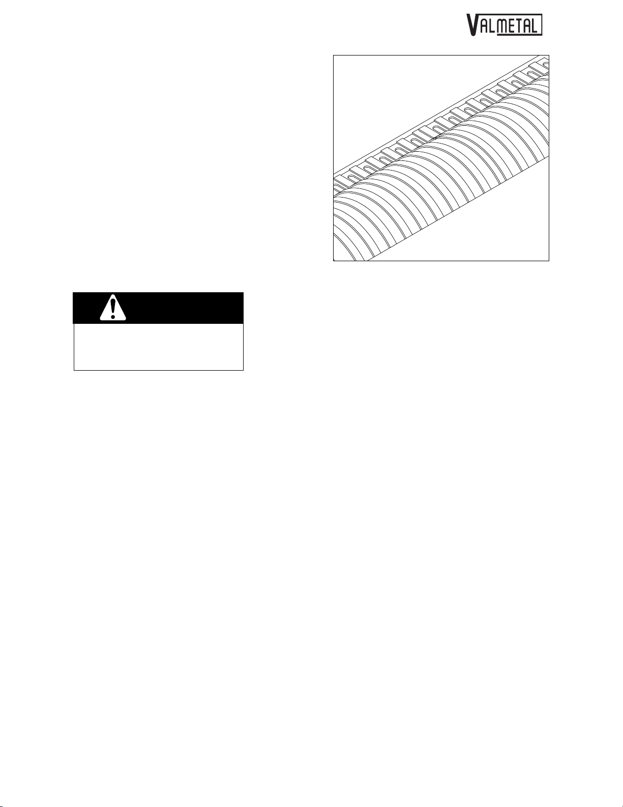
5.2.1 KNIVES REPLACEMENT
The knives are located on the rotor in the bottom of
the tub. After long periods of use, they can wear.
They can also be damaged when a hard object goes
through the machine. If worn or damaged, they will
have to be replaced.
To replace knives, follow this procedure:
1. Clear the area of bystanders.
2. Stop the tub when the tub doors are at 90
0
to the
direction of travel.
3. Place all controls in neutral, stop engine, set
park brake, remove ignition key and wait for all
moving parts to stop before dismounting.
4. Disconnect PTO driveline to release the rotor.
5. Remove the nuts and bolts holding the grate
arms(A) to the hydraulic cylinders. Then, lower
the grate arm(A) in order to raise the grate to its
highest position. Tie one of the grate arm to the
machine's frame using a chain(B). This
way, the grate will be held-up allowing you to
change the broken knives. See figure 31-A.
6. Open tub doors.
7. Turn the rotor by hand to bring the damaged or
broken knives to the top side.
8. Remove the bolts and replace knives.
9. Tighten mounting bolts to their specified torque.
10. Inspect all knives by rotating the rotor by hand.
Replace as required.
11. Close and latch tub doors and connect driveline
to tractor.
Fig. 32 KNIVES
Fig. 31-A GRATE MUST BE HELD UP IN ORDER
TO REPLACE BROKEN KNIVES.
SERVICE & MAINTENANCE
37
A
B

SERVICE & MAINTENANCE
38
5.2.2 BELT AND ROLLER CHAINS
The tension of the belts and roller chains are controlled by the tension springs on each drive. The
springs should always be set to have a coil spacing of
at least 3 mm (1/8 inch) for the best operation.
To adjust the length of the springs, follow this
procedure:
1. Clear the area of bystanders.
2. Place all controls in neutral, stop engine, set
park brake, remove ignition key and wait for all
moving parts to stop before dismounting.
3. Remove guard covering drive.
4. Either replace the spring or use the nut on the
anchor bolt to change the spring length to
maintain the coil spacing of 3 mm (1/8 inch).
5. If this does not work, the roller chain or belt must
be replaced.
6. To replace, remove spring and remove the belt
or chain.
7. Replace with genuine ValMetal replacement
parts.
NOTE
Use only matched belts for
each multiple belt.
8. Install spring tensioner.
9. Install and secure guard.
WARNING
Machine is shown with guard removed for
illustrative purposes only. Do not operate
machine with guard removed.
Fig. 33 ROTOR DRIVE BELT SPRING
Fig. 34 TUB DRIVE CHAIN SPRING
Fig. 35 REAR SPRING TENSIONERS
G

5.2.3 GEARBOX OIL
The oil level in the gearbox must be checked every 3
months or after 200 bales to insure that the gears
have proper lubrication. If leakage is observed, check
the oil level more frequently.
To check the oil level, follow this procedure:
1. Place all controls in neutral, stop the engine,
remove the ignition key and wait for all moving
parts to stop before dismounting.
2. Remove front guard.
3. Remove oil level plug "B" on the side of the gear
box. Remove fill-up cap “A”.
4. Add through the fill plug "A" until the oil just starts
to come out of the level plug “B”.
5. Install and tighten the fill and level plugs.
6. To change the oil in the gearbox, it is necessary
to remove the gearbox. Remove the tub drive
chain, the belts and then remove the 8 bolts
holding the gearbox.
7. Drain into a container and place in an approved
disposal site.
8. Install the drain plug and tighten.
9. Add oil through the fill plug until oil starts to come
out of the level plug hole.
10. Tighten all plugs.
11. Install and secure the guard.
WARNING
Machine is shown with guard removed for
illustrative purposes only. Do not operate
machine with guard removed.
Fig. 36 GEARBOX
SERVICE & MAINTENANCE
39
A
B

SERVICE & MAINTENANCE
40
5.2.4 BREATHER CLEANING
The breather must be able to vent to atmospheric
conditions during the heating and cooling cycles while
operating. If it cannot, oil will seep out the seals and
the machine will run low on oil. Prolonged operation
with low oil levels will damage the internal working
components.
To clean:
1. Remove the breather.
2. Stop up the breather opening using a plastic plug
or a clean rag to prevent contaminants from
entering the gearbox.
3. Soak the breather in solvent for one hour.
4. Use a pointed instrument or a wire to remove
any residue from the breather passages.
5. Blow out using high-pressure air.
6. Blow through the breather to insure that the
passages are clear.
7. Install and tighten breather in the gearbox.
Fig. 37 BREATHER

5.2.5. OVER RUNNING CLUTCH & SHEAR PINS
The Over Running Clutch is pre-set from the factory and does not require adjustment.
The machine is also equipped with 2 shear pins. The PTO shear pin is located on the PTO drive (figure 38)
and the auger shear pin is located at the end of the auger shaft (figure 39). These shear pins will break in the
event of an overload. Replace when a pin breaks. IMPORTANT! Do not redrill and replace pin with a larger one. Replace with same size and same grade pin (12mm x 65mm, grade 8.8).
Fig. 38 PTO SHEAR PIN (12mm x 65mm, grade 8.8)
Fig. 39 AUGER SHEAR PIN (1/4” x 1 1/2”, grade 2)
SERVICE & MAINTENANCE
41

SERVICE & MAINTENANCE
42

TROUBLE SHOOTING
43
SECTION 6 TROUBLE SHOOTING
The ValMetal Round Bale Grinder uses a rotor with sickle sections to grind round bales into small pieces. It is
a reliable system that requires minimal maintenance.
In the following section, we have listed many of the problems, causes and solutions to the problems that
you may encounter.
If you encounter a problem that is difficult to solve, even after having read through this trouble shooting section, please call your ValMetal representative or the factory. Before you call, please have this Operator's
Manual and the serial number from your Grinder ready.
PROBLEM
Rotor does not turn.
Noisy rotor.
Blower plugging.
Auger plugging
CAUSE
Material plugged in rotor.
Shear pin on PTO broken.
Knives contacting housing.
Blower not empty.
Shear pin broken
Drive chain broken
SOLUTION
Remove material causing plug.
Replace Shear pin
Bent knife. Straighten or replace
knife.
Object lodged in rotor housing.
Remove object.
Allow machine to empty before
stopping.
Raise grate to slow feeding rate.
Use larger tractor.
Replace tension springs or belts
as required.
Unplug and replace shear pin
Replace chain

PROBLEM
Poor grinding production rate.
Tub won't turn.
CAUSE
Broken knives.
Knives covered.
Grate too high.
Baffles closed.
Drive problem.
SOLUTION
Replace knives.
Remove entangled material.
Lower grate.
Release baffles to turn bale.
Replace belt. Repalce spring
tensioner.
Replace gearbox.
TROUBLE SHOOTING
44

SPECIFICATIONS
45
SECTION 7 SPECIFICATION
7.1 MECHANICAL
SPECIFICATIONS SUBJECT TO CHANGE WITHOUT NOTICE
MODEL
Overall Length:
Overall Width:
Height
(without Chute):
Height
(with Chute):
Tub Dimentions:
Maximum Bale
Dimentions:
Minimum H.P.
Recommended at
the PTO:
Adjustable Grate:
Fine Cut Rotor:
Blades:
PTO Shaft With
Friction Plates:
Tire Size:
Machine Weight:
H-5500
163"
(414 cm)
90"
(229 cm)
74"
(188 cm)
106"
(269 cm)
36" X 84"
(91 X 213 cm)
60" X 60"
(152 X 152 cm)
70 H.P
Standard
Optional
(regular) 156
(fine cut) 312
Included
11L-15 (8 Ply)
4260 lbs
(1936 kg)
H-5600
175"
(444 cm)
102"
(259 cm)
80"
(203 cm)
106"
(269 cm)
42" X 96"
(107 X 244 cm)
60" X 72"
(152 X 183 cm)
80 H.P
Standard
Optional
(regular) 180
(fine cut) 360
Included
11L-15 (8 Ply)
4740 lbs
(2155 kg)

7.2 BOLT TORQUE
CHECKING BOLT TORQUE
The tables shown below give correct torque values for various bolts and capscrews. Tighten all bolts to the
torques specified in chart unless otherwise noted. Check tightness of bolts periodically, using bolt torque
chart as a guide. Replace hardware with the same strength bolt.
ENGLISH TORQUE SPECIFICATIONS
METRIC TORQUE SPECIFICATIONS
Torque figures indicated above are valid for non-greased or non-oiled threads and heads unless otherwise
specified. Therefore, do not grease or oil bolts or capscrews unless otherwise specified in this manual.
When using locking elements, increase torque values by 5%.
* Torque value for bolts and capscrews are identified by their head markings.
SPECIFICATIONS
46
Bolt
DiameterSAE 2
N.m.
"A"
1/4"
5/16"
3/8"
7/16"
1/2"
9/16"
5/8"
3/4"
7/8"
1"
8
13
27
41
61
95
128
225
230
345
Bolt Torque*
SAE-5
(lb-ft)
N.m.
(6)
(10)
(20)
(30)
(45)
110
(70)
155
(95)
215
(165)
390
(170)
570
(225)
850
12
25
45
72
(lb-ft)
(9)
(19)
(33)
(53)
(80)
(115)
(160)
(290)
(420)
(630)
N.m.
.5
3
6
10
25
50
90
140
225
435
750
1495
2600
Bolt Torque
(lb-ft)
(.6)
(2.2)
(18)
(37)
(66)
(103)
(166)
(321)
(553)
(1103)
(1917)
N.m.
(4)
(7)
125
200
310
610
1050
2100
3675
10.9
1.8
4.5
9
15
35
70
(lb-ft)
(1.3)
(3.3)
(7)
(11)
(26)
(52)
(92)
(148)
(229)
(450)
(774)
(1550)
(2710)
Bolt
Diameter8.8
"A"
M3
M4
M5
M6
M8
M10
M12
M14
M16
M20
M24
M30
M36
SAE 8
N.m.
17
36
63
100
155
220
305
540
880
1320
(lb-ft)
(12)
(27)
(45)
(75)
(115)
(165)
(220)
(400)
(650)
(970)
SAE-5SAE-2 SAE-8
A
A
8.8 8.8

7.3 HYDRAULIC FITTING TORQUE
TIGHTENING FLARE TYPE TUBE FITTING*
1. Check flare and flare seat for defects that
might cause leakage.
2. Align tube with fitting before tightening.
3. Lubricate connection and hand tighten
swivel nut until snug.
4. To prevent twisting the tube(s), use two
wrenches. Place one wrench on the
connector body and with the second
tighten the swivel nut to the torque shown.
* The torque values shown are based on
lubricated connections as in reassembly.
Recommended
Nut Size Turns to Tighten
Tube Across (After Finger
Size Flats Torque Value* Tightening)
OD
(in.) (in.) (N.m) (lb-ft) (Flats) (Turns)
3/16 7/16 8 6 1 1/6
1/4 9/16 12 9 1 1/6
5/16 5/8 16 12 1 1/6
3/8 11/16 24 18 1 1/6
1/2 7/8 46 34 1 1/6
5/8 1 62 46 1 1/6
3/4 1-1/4 102 75 3/4 1/8
7/8 1-3/8 122 90 3/4 1/8
SPECIFICATIONS
47
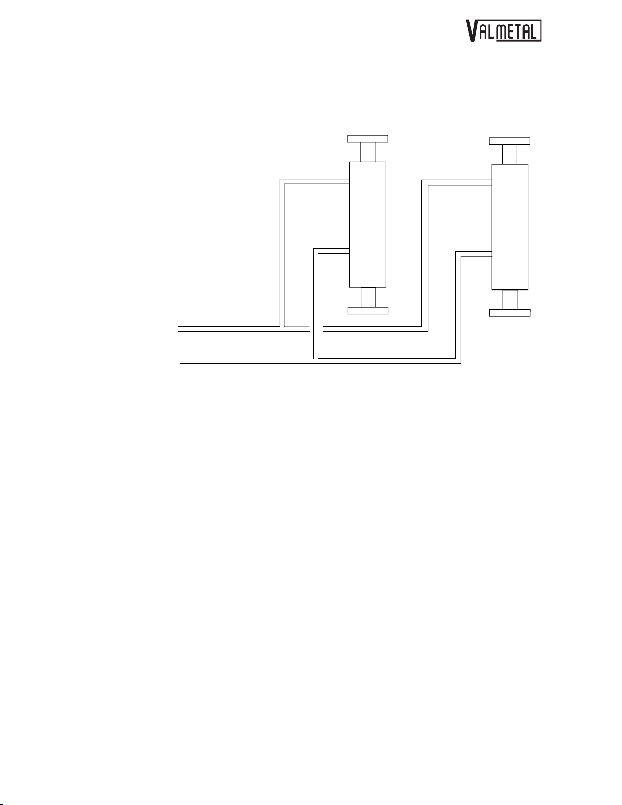
7.4 HYDRAULIC CIRCUIT
SPECIFICATIONS
48
GRATE CYLINDERS
TO TRACTOR


3
2
17
CHASSIS
FRAME
53
52
51
14
10
15
16
17
4
5
6
9
12
11
31
1
7
8
8
18
19
37
47
49
50
46
13
21
20
23
24
22
26
25
29
32
27
28
33
30
34
54
35
36
52
38
53
40
40
39
41
45
44
48
43
42
A

A
A
AGRI-CHOPPER (MOD:5500-H & 5600-H)
REF. PART NO DESCRIPTION QTY
1 17A50-0000 BODY (MOD.5500) 1
17A50-0002 BODY (MOD:5600) 1
2 17A01-1550 TUB BEARING GUARD 3
3 17A05-2020 BEARING HOLDER'S BRACKET 1
4 17A55-0005 TUB BEARING COMPL."BEARING INCLUDED"
17A21-0000 TUB BEARING
14C75-0070 BALL BEARING 6205-2RS X Ø 1" 2
5 17A09-1220 BUSHING 1" Dia. X Ø 3/4" X 2.3/8" LG 1
6 17A09-0500 FLAT WASHER 1 3/4" Dia. X 3/4" X 1/4" LG 1
7 17A55-0010 BALL BEARING COMPL. 4
14C75-0071 BALL BEARING 6207-2RS 2
17A13-2425 ROLLER BEARING SPACER SEAL 2
17A13-2420 ROLLER BEARING SPACER 1
8 17A04-0046 FLAT WASHER 1 3/4" Dia. X Ø 33/64" X 3/16" 2
9 13C45-0018 HYDRAULIC CYLINDER COMPL."BUSHING INCLUDED" 1
17A55-0312 HYDRAULIC CYLINDER COMPL."BUSHING INCLUDED" (PAPER OPTION) 1
17A09-0605 CYLINDRE SPEACER 1 5/8" Dia. X Ø 1 1/4" X 1" LG 1
10 17A50-0045 FRONT HYDRAULIC CYLINDER ARM 1
11 17A57-0030 GRATE ADJUSTMENT BUSHING (KIT) 1
12 17A50-0050 ROTOR COVER (FRONT) 1
13 14C25-0620 V-BELT B-111 (5/8" X 114") (MOD. 5500) 2
14C25-0625 V-BELT B-122 (5/8" X 125") (MOD. 5600) 2
14 17A55-0230 P.T.O. SHAFT ADAPTOR COMPL."BOLT AND NUT INCLUDED" 1
15 17A36-0500 SPROCKET 60B16 X Ø2" KW 1/2" 1
16 17A21-0005 BEFORE -08/92 #00000- ROTOR'S PULLEY 6" Dia. X 2 5/8" LONG 1
17A43-0000
17 14C75-0028 BEFORE -03/99 #19306- FLANGE BEARING UCF 311-32 X Ø 2" X Ø 1/4"-28 1
17A38-0000
18 17A42-0110 NYLON SKATE 1
19 01C09-0010 PLOW BOLT 3/8"-16 X 1" LG "GRADE 5" 3
20 17A05-2010 CHAIN TIGHTNER ARM (AUGER) 1
21 02A39-0605 IDLER PULLEY PI-400 COMPL. 1
22 13C85-0010 GALV.SPRING 1" Dia. X 5 1/2" LG 1
23 01C52-0014 EYE BOLT 3/8"-16 X 5" LG 1
FTER -08/92 #00000- CAST IRON PULLEY 2MB60. X Ø 2" KW 1/2" (SPECIAL) 1
FTER -03/99 #19306- FLANGE BEARING UCF 311-32 X Ø 2" X Ø 1/8 NPT 1
4
1
revised: 2007-07-30
A-1

AGRI-CHOPPER (MOD:5500-H & 5600-H)
A
A
A
A
A
REF. PART NO DESCRIPTION QTY
24 09A41-0900 SQUARE KEY 3/8" X 3/8" X 1 1/2" LG 1
25 17A55-0235 SHEAR PIN HOLDER COMPL."BOLT AND NUT INCLUDED" 1
26 17A55-0380 SHEAR BOLT COMPL.1/4"-20 X 1 1/2" LG "NUT AND FLAT WASHER INCLUDED" 1
27 17A37-1374 BEFORE -06/94 #13625- CHAIN #60 X 66"+ 1/2 MAILLE LG (VIS 12"Dia.) 1
17A37-1375
28 17A55-0015
17A36-0505 BEFORE -06/94 #13625- SPROCKET 60B60 X Ø 1 3/4" 1
13C80-0056 BEFORE -06/94 #13625- OILITE BHSHING 1 1/2" Dia. X Ø 1 3/4" X 1 3/4" LG 1
17A55-0020
17A36-0510
13C80-0056
29 14C75-0025 BEFORE -03/99 #19306- FLANGE BEARING UCF 208-24 X Ø 1 1/2 X Ø 1/4"-28 1
17A38-0010
30 13C80-0061 BUSHING 5/8" X 1/2" X 3/8" 4
31 17A05-1100 ROTOR COVER BRACKET 1
32 17A09-1200 BUSHING 1" X 1/2" X 2" LG 1
33 17A55-0035 IDLER PULLEY COMPL."BALL BEARING INCLUDED" 1
17A21-0010 IDLER PULLEY 1
14C75-0070 BALL BEARING 6205-2RS X Ø 1" 2
34 17A50-0040 BELT TIGHTNER ARM (TUB) 1
35 13C85-0010 GALV.SPRING 1" Dia. X 5 1/2" LG 1
36 01C52-0014 EYE BOLT 3/8"-16 X 5" LG 1
37 01C45-0256 METRIC BOLT 12MM X 25MM (GRADE 8.8) 8
38 14C62-0020 TAPERED QD BUSHING SK 1 3/8" KW 5/16" 1
39 14C62-0090 CAST IRON SHAVE PULLEY 2B7.4 SK 1
40 01A41-0915 SQUARE KEY 5/16" X 5/16" X 1 1/2" LG 2
41 17A34-0100 TRANSMISSION ANGLE GEAR BOX 1
13C65-0003 GALV.ELBOW 90° 3/8 FEM. NPT X 3/8 MALE NPT 1
01C64-0186 AIR VENT 3/8"-18 NPT 1
42 17A04-2800 CHA1N LIGHTNER SUPPORT 1
43 17A05-2000 CHAIN TIGHTNER (TUB) 1
44 17A57-0000 SPROCKET ADJUSTMENT BUSHING (KIT) 1
45 01C64-0029 RETAINING RINGS 2" Dia. 1
46 17A55-0045 SPROCKET 80B18 X SD COMPL."TAPERED QD BUSHING INCLUDED" 1
FTER -06/94 #13625- CHAIN #60 X 79" + 1/2 MAILLE LG 1
BEFORE -06/94 #13625- SPROCKET 60B60 X Ø 1 3/4 COMPL." OILITE BUSHING INCLUDED " (VIS
12"Dia.) 1
FTER -06/94 #13625- SPROCKET 60B80 X Ø 1 3/4 COMPL." OILITE BUSHING INCLUDED " (VIS
16"Dia.) 1
FTER -06/94 #13625- SPROCKET 60B80 X Ø 1 3/4 " 1
FTER -06/94 #13625- OILITE BHSHING 1 1/2" Dia. X Ø 1 3/4" X 1 3/4" LG 1
FTER -03/99 #19306- FLANGE BEARING UCF 208-24 X Ø 1 1/2 X Ø 1/8 NPT 1
revised: 1999-01-01
A-2

AGRI-CHOPPER (MOD:5500-H & 5600-H)
REF. PART NO DESCRIPTION QTY
17A36-0600 SPROCKET 80B18 1
14C62-0006 TAPERED QD BUSHING SD 1 3/8" KW 5/16" 1
47 13C85-0003 EXTENSION SPRING 1 1/2" Dia. X 6 1/2" LONG 1
48 17A50-0055 BOLT 7/16"-14 X 5 1/2" LG (SPECIAL) 1
49 17A55-0040 SPROCKET 80B17 X Ø 1" COMPL."BEARING INCLUDED" 1
17A36-0605 SPROCKET 80B17 1
14C75-0070 BALL BEARING 6205-2RS X Ø 1" 2
50 17A09-1215 BUSHING 1" Dia. X Ø 1/2" X 1 1/2" LG 1
51 17A55-0394 SINCE -03/99 #19306- GREASE HOSE 1/4"-H ASS. X 28" LG 1
52 13C65-0001 SINCE -03/99 #19306- BRASS COUPLING 1/4 NPT X 7/8" LG 2
53 01C69-0798 SINCE -03/99 #19306- GREASE FITTING 1/4 NPT X DROIT 2
54 17A55-0391 SINCE -03/99 #19306- GREASE HOSE 1/4"-H ASS. X 10" LG 1
revised: 1999-01-01
A-3

10
CHASSIS (SUITE)
1
2
4
5
7
5
17
FRAME (CONT'D)
8
7
9
17
ValMetal
1006, rue Principale, Wickham, Qué
11
3
6
18
. Canada J0C 1S0
16
14
13
15
12
B

AGRI-CHOPPER (MOD:5500-H & 5600-H)
REF. PART NO DESCRIPTION QTY
1 17A50-0005 FINE CUT GRATE (MOD. 5500) 1
17A50-0010 FINE CUT GRATE (MOD. 5600) 1
17A50-0240 GRATE (PAPER OPTION) MOD.5500 1
17A50-0245 GRATE (PAPER OPTION) MOD.5600 1
2 09A41-0900 SQUARE KEY 3/8" X 3/8" X 1 1/2" LG 1
3 17A55-0165 ROTOR COMPL."STANDARD" 156 KNIVES (MOD.5500) 1
17A50-0290 ROTOR SHAFT (STANDARD) MOD. 5500 1
4 13C22-0002 SINGLE KNIVES 108
5 17A50-0345 HEAVY DUTY KNIVES (4 FIRST ROW ON EACH SIDE) 48
01C37-0058 BOLT HEX.5/16"-24 X 3/4" LG (GRADE 8) 216
01C37-0059 BOLT HEX.5/16"-24 X 7/8" LG (GRADE 8) 96
01C94-0002 STOVER LOCKNUT 5/16"-24 312
3 17A55-0170 ROTOR COMPL."STANDARD" 180 KNIVES (MOD.5600) 1
17A50-0295 ROTOR SHAFT (STANDARD) MOD. 5600 1
4 13C22-0002 SINGLE KNIVES 120
5 17A50-0345 HEAVY DUTY KNIVES (5 FIRST ROW ON EACH SIDE) 60
01C37-0058 BOLT HEX.5/16"-24 X 3/4" LG (GRADE 8) 240
01C37-0059 BOLT HEX.5/16"-24 X 7/8" LG (GRADE 8) 120
01C94-0002 STOVER LOCKNUT 5/16"-24 360
3 17A55-0175 ROTOR COMPL."FINE CUT" 312 KNIVES (MOD.5500) 1
17A50-0290 ROTOR SHAFT (STANDARD) MOD. 5500 1
4 13C22-0002 SINGLE KNIVES 216
5 17A50-0345 HEAVY DUTY KNIVES (4 FIRST ROW ON EACH SIDE) 96
01C37-0058 BOLT HEX.5/16"-24 X 3/4" LG (GRADE 8) 432
01C37-0059 BOLT HEX.5/16"-24 X 7/8" LG (GRADE 8) 192
01C94-0002 STOVER LOCKNUT 5/16"-24 624
3 17A55-0180 ROTOR COMPL."FINE CUT" 360 KNIVES (MOD.5600) 1
17A50-0295 ROTOR SHAFT (STANDARD) MOD. 5600 1
4 13C22-0002 SINGLE KNIVES 240
5 17A50-0345 HEAVY DUTY KNIVES (5 FIRST ROW ON EACH SIDE) 120
01C37-0058 BOLT HEX.5/16"-24 X 3/4" LG (GRADE 8) 480
01C37-0059 BOLT HEX.5/16"-24 X 7/8" LG (GRADE 8) 240
01C94-0002 STOVER LOCKNUT 5/16"-24 720
3 17A55-0185 ROTOR COMPL."STANDARD" (PAPER OPTION) 156 KNIVES (MOD.5500) 1
revised: 1999-01-01
B-1

AGRI-CHOPPER (MOD:5500-H & 5600-H)
A
A
Â
A
A
REF. PART NO DESCRIPTION QTY
17A50-0300 ROTOR SHAFT (PAPER OPTION) MOD. 5500 1
5 17A50-0345 HEAVY DUTY KNIVES 156
01C37-0059 BOLT HEX.5/16"-24 X 7/8" LG (GRADE 8) 312
01C94-0002 STOVER LOCKNUT 5/16"-24 312
3 17A55-0190 ROTOR COMPL."STANDARD" (PAPER OPTION) 180 KNIVES (MOD.5600) 1
17A50-0305 ROTOR SHAFT (PAPER OPTION) MOD.5600 1
5 17A50-0345 HEAVY DUTY KNIVES 180
01C37-0059 BOLT HEX.5/16"-24 X 7/8" LG (GRADE 8) 360
01C94-0002 STOVER LOCKNUT 5/16"-24 360
3 17A55-0195 ROTOR COMPL."FINE CUT" (PAPER OPTION) 312 KNIVES (MOD.5500) 1
17A50-0300 ROTOR SHAFT (PAPER OPTION) MOD. 5500 1
5 17A50-0345 HEAVY DUTY KNIVES 312
01C37-0059 BOLT HEX.5/16"-24 X 7/8" LG (GRADE 8) 624
01C94-0002 STOVER LOCKNUT 5/16"-24 624
3 17A55-0200 ROTOR COMPL."FINE CUT" (PAPER OPTION) 360 KNIVES (MOD.5600) 1
17A50-0305 ROTOR SHAFT (PAPER OPTION) MOD.5600 1
5 17A50-0345 HEAVY DUTY KNIVES 360
01C37-0059 BOLT HEX.5/16"-24 X 7/8" LG (GRADE 8) 720
01C94-0002 STOVER LOCKNUT 5/16"-24 720
6 17A41-0900 SQUARE KEY 1/2" X 1/2" X 7 1/2" LG 1
7 17A55-0060 BEFORE -12/94 #14223- HYDR.HOSE 1/2-H ASS.1/2-14 MALE RIG.X 1/2-14 MALE SWI.X 60" LG 4
17A55-0061
17A55-0065 BEFORE -12/94 #14314- HYDR.HOSE 1/2-H ASS.1/2-14 MALE RIG.X 1/2-14 MALE SWI.X 66" LG 4
17A55-0066
8 17A55-0070 HYDR.HOSE 1/2-H ASS.1/2-14 MALE RIG.X 1/2-14 MALE SWI.X 140" LG 2
17A55-0075 HYDR.HOSE 1/2-H ASS.1/2-14 MALE RIG.X 1/2-14 MALE SWI.X 146" LG 2
9 13C45-0014 QUICK DISCON.COUPLER 1/2 NPT 2
10 13C45-0033 BEFORE -12/94 #14314- T 1/2 FEM. NPT X 1/2 FEM. NPT X 1/2 M
13C45-0024 BEFORE -12/94 #14314- 90° COUDE 1/2 FEMALE NPT X 1/2 FEMELLE NPT 2
17A21-0200
11 17A34-0031 PTO SHAFT (T80) 1 3/8" 6 SPLINES X 46 7/16" LG 1
12 17A50-0070 BEFORE -08/94 #13697- AUGER 12" Dia. (MOD.5500) 1
17A50-0080
17A50-0075 BEFORE -06/94 #13625- AUGER 12" Dia. (MOD.5600) 1
FTER -12/94 #14223- HYDR.HOSE 3/8-H ASS.3/8-18 MALE RIG.X 3/8-18 MALE SWI.X 60" LG 4
FTER -12/94 #14314- HYDR.HOSE 3/8-H ASS.3/8-18 MALE RIG.X 3/8-18 MALE SWI.X 66" LG 4
LE NPT 2
FTER -12/94 #14314- HYDRAULIC DOUBLE T BLOC 1
FTER -08/94 #13697- AUGER 16" Dia. (MOD.5500) 1
revised: 1999-01-01
B-2

AGRI-CHOPPER (MOD:5500-H & 5600-H)
A
REF. PART NO DESCRIPTION QTY
17A50-0085
13 17A11-3515 AUGER'S SPACER BUSHING 1
14 17A55-0295 FRONT GUARD COMPL."STICKER INCLUDED" (MOD.5500) 1
17A55-0296 FRONT GUARD COMPL."STICKER INCLUDED" (MOD.5600) 1
15 17A55-0291 GEAR BOX GUARD "STICKER INCLUDED" (MOD.5500) 1
17A55-0292 GEAR BOX GUARD "STICKER INCLUDED" (MOD.5600) 1
16 17A55-0385 JACK "COTTER PIN INCLUDED" 1
17 17A42-0135 HYDRAULIC HOSE PROTECTOR 1
18 17A55-0345 AUGER ACCESS DOOR COMPL."STICKER INCLUDED" 3
FTER -06/94 #13625- AUGER 16" Dia. (MOD.5600) 1
revised: 1999-01-01
B-3

37
38
48
47
17
SOUFFLEUR (MODÈLE H)
BLOWER (MODEL H)
40
41
10
42
46
48
32
30
31
24
25
28
23
39
36
33
35
34
47
28
29
49
21
3
2
15
14
1
11
16
17
19
18
20
22
43
45
44
inc.
8
9
4
6
7
5
12
13
26
27
ickham, Québec J0C 1S0
Valmetal
1006, rue Principale, W
C

A
A
AGRI-CHOPPER (MOD:5500-H & 5600-H)
REF. PART NO DESCRIPTION QTY
1 14C70-0012 WHEEL 15" COMPL. 2
14C70-0052 TIRE 1
14C70-0009 RIM 1
14C70-0016 TUBE 1
2 17A55-0100 WHEEL'S HUB COMPL. 2
17A46-0615 HUB 1
14C70-0014 TAPERED BEARING 1
14C70-0017 SEAT FOR TAPERED BEARING 1
14C70-0015 TRUST BEARING 1
14C70-0018 SEAT TRUST BEARING 1
14C70-0010 SEAL 1
14C70-0060 FLAT WASHER 1 3/4" Dia. X Ø 1 1/8" X 1/8" 1
14C70-0007 CASTLE NUT 1"-14 UNF 1
14C70-0008 COTTER PIN 3/16" X 1 1/2" LG 1
14C70-0006 DUST CAP 1
14C70-0005 WHEEL BOLT 6
3 17A46-0645 WHEEL AXLE 1 3/4" Dia. X 10 " LG 2
4 17A55-0090 BELT TIGHTNER COMPL."BEARING INCLUDED" 1
5 17A50-0140 BELT TIGHTNER 1
6 17A50-0030 IDLER PULLEY SUPPORT 1
7 17A55-0383 IDLER PULLEY AXLE "BOLT AND NUT INCLUDED" 1
8 17A55-0095 IDLER PULLEY COMPL."BEARING INCLUDED" 1
17A21-0020 IDLER PULLEY 6" Dia. X 3 1/2" LG 1
14C75-0070 BALL BEARING 6205-2RS X Ø 1" 2
9 17A09-1210 BUSHING 1" X 1/2" X 3 1/2" LG 1
10 17A04-0050 BELT ROLLER BRACKET 2
11 17A55-0330 BELT ROLLER STOPPER COMPL."BEARING INCLUDED" 1
12 13C85-0022 GALV. RESSORT 1 3/8" Dia. X 9 1/2" LG 4
13 14C25-0576 V-BELT B-62 (5/8" X 65") 3
14 14C62-0107 CAST IRON SHAVE PULLEY 4B6.6 1
14C62-0005 BEFORE -02/97 #16436 TAPERED QD BUSHING SD 1 1/4" 1
14C62-0007
15 01A41-0910 BEFORE -02/97 #16436 SQUARE KEY 1/4" X 1/4" X 1 1/2" LG 1
12A41-0915
FTER -02/97 #16436 TAPERED QD BUSHING SD 1 1/2" 1
FTER -02/97 #16436 SQUARE KEY 3/8" X 3/8" X 1 3/4" LG 1
revised: 1999-01-01
C-1

AGRI-CHOPPER (MOD:5500-H & 5600-H)
A
A
A
A
A
A
REF. PART NO DESCRIPTION QTY
16 17A42-0010 BEFORE -02/97 #16436 JACK SHAFT PROTECTOR 1 1/4" Dia. X 10 3/8" LG 1
17A42-0025
17 14C75-0034 BEFORE -02/97 #16436 PILLOW BEARING UCP 207-20 X Ø 1 1/4" 1
14C75-0035
18 14C62-0104 CAST IRON SHAVE PULLEY 3B9.4 SK 1
14C62-0019 BEFORE -02/97 #16436 TAPERED QD BUSHING SK Ø 1 1/4" K.W. 5/16" (PTO) 1
14C62-0021
19 01A41-0910 BEFORE -02/97 #16436 SQUARE KEY 1/4" X 1/4" X 1 1/2" LG 1
12A41-0915
20 17A20-0050 BEFORE -02/97 #16436 JACK SHAFT 1 1/4" Dia. X 20 1/4" LG 1
17A13-2435
21 13C80-0004 LOCK 1
22 17A55-0080 IMPELLER COMPL. 1
17A50-0115 IMPELLER' HUB 1
23 17A50-0120 PADLE 4
24 17A50-0125 PADLE LOCKER PIN 4
25 17A55-0325 COVER COMPL."STICKER INCLUDED" 1
26 17A55-0337 ACCESS DOOR "STICKER INCLUDED" 1
27 17A55-0323 BELT'S GUARD "STICKER INCLUDED" 1
28 14C75-0024 BEFORE -03/99 #19306- FLANGE BEARING 4 Ø UCF 207-20 X Ø 1 1/4" X Ø 1/4"-28 1
17A38-0005
29 12A09-1015 BUSHING 2" X 1 1/4" X 3/4" LG 1
30 14C62-0100 CAST IRON SHEAVE PULLEY 3B5.6 1
14C62-0005 TAPERED QD BUSHING SD 1 1/4" 1
31 01A41-0910 SQUARE KEY 1/4" X 1/4" X 1 1/2" LG 1
32 17A55-0328 BOLT 3/8"-16 X 10" LG (GRADE 2) "NUT AND LOCK WASHER INCLUDED" 2
17A55-0327 BOLT 3/8"-16 X 9" LG (GRADE 2) "NUT AND LOCK WASHER INCLUDED" 11
17A55-0326 BOLT3/8"-16 X 2 1/2" LG (GRADE 2) "NUT AND LOCK WASHER INCLUDED" 3
33 17A55-0240 BELT'S TIGHTNER COMPL."IDLER PULLEY INCLUDED" 1
17A50-0130 BLOWER BELT'S TIGHTNER 1
34 17A55-0085 IDLER PULLEY COMPL."BEARING INCLUDED" 1
17A21-0015 IDLER PULLEY 6" Dia. X 2 7/8" LG 1
14C75-0070 BALL BEARING 6205-2RS X Ø 1" 2
35 17A09-1205 BUSHING 1" X Ø 1/2" X 2 3/4" LG 1
FTER -02/97 #16436 JACK SHAFT PROTECTOR 2 3/8" Dia. X 10 1/8" LG 1
FTER -02/97 #16436 PILLOW BEARING UCP 208-24 X Ø 1 1/2" 2
FTER -02/97 #16436 TAPERED QD BUSHING SK 1 1/2" KW 3/8" 1
FTER -02/97 #16436 SQUARE KEY 3/8" X 3/8" X 1 3/4" LG 1
FTER -02/97 #16436 JACK SHAFT 1 3/4" Dia. X 20 1/2" LG 1
FTER -03/99 #19306- FLANGE BEARING UCF 207-20 X Ø 1 1/4" X Ø 1/8 NPT 1
revised: 1999-01-01
C-2

AGRI-CHOPPER (MOD:5500-H & 5600-H)
A
A
A
A
A
REF. PART NO DESCRIPTION QTY
36 13C85-0022 GALV. RESSORT 1 3/8" Dia. X 9 1/2" LG 2
37 17A55-0321 TOP BELT'S GUARD "STICKER INCLUDED" 1
38 17A42-0105 NYLON RING 2
39 17A05-1100 ROTOR COVER BRACKET 1
40 17A50-0110 BACK COVER (ROTOR) 1
41 17A50-0330 BACK HYDRAULIC CYLINDRE ARM 1
42 14C75-0028 BEFORE -03/99 #19306- FLANGE BEARING UCF 311-32 X Ø 2" X Ø 1/4"-28 1
17A38-0000
43 14C62-0109 CAST IRON SHAVE PULLEY 4B9.4 1
09A39-0370 TAPERED QD BUSHING SK 1 3/4" (SPECIAL) 1
44 09A41-0900 SQUARE KEY 3/8" X 3/8" X 1 1/2" LG 1
45 14C25-0603 V-BELT B-89 (5/8" X 92") 4
46 17A55-0392
47 13C65-0001
48 01C69-0798
49 17A55-0393
FTER -03/99 #19306- FLANGE BEARING UCF 311-32 X Ø 2" X Ø 1/8 NPT 1
FTER -03/99 #19306- GREASE HOSE 1/4"-H ASS. X 12" LG 1
FTER -03/99 #19306- BRASS COUPLING 1/4 NPT X 7/8" LG 2
FTER -03/99 #19306- GREASE FITTING 1/4 NPT X DROIT 2
FTER -03/99 #19306- GREASE HOSE 1/4"-H ASS. X 24" LG 1
revised: 1999-01-01
C-3

13
12
CUVE
17
2
TUB
15
14
1
4
11
10
9
10
9
R
R
E
E
P
P
P
P
H
H
C
C
7
6
5
3
8
17
19
18
16
D

REF. PART NO DESCRIPTION QTY
1 17A55-0299 ROUND TUB COMPL."STICKER INCLUDED" (MOD:5500) 1
17A55-0300 ROUND TUB COMPL."STICKER INCLUDED" (MOD:5600) 1
2 17A55-0278 RIGHT DOOR COMPL."STICKER INCLUDED" (MOD:5500) 1
17A55-0279 RIGHT DOOR COMPL."STICKER INCLUDED" (MOD:5600) 1
3 17A55-0276 LEFT DOOR COMPL."STICKER INCLUDED" (MOD:5500) 1
17A55-0277 LEFT DOOR COMPL."STICKER INCLUDED" (MOD:5600) 1
4 17A50-0185 HINGE'S (MOD.5500) 1
17A50-0190 HINGE'S (MOD.5600) 1
5 17A50-0195 DOOR'S LOCK 1
6 13C15-0009 RUBBER HANDLE 1
7 17A55-0110 COMPLET MANUAL WINCH W/HANDLE 1
13C80-0038 MANUAL WINCH WO/HANDLE 1
17A50-0340 WINCH HANDLE ONLY 1
8 17A37-1450 CHAIN #80 X 292" LG (MOD.5500) 1
17A37-1451 CHAIN #80 X 332" LG (MOD.5600) 1
9 17A42-0115 PULLEY 4" Dia. X 1 1/4" LG 2
10 12A09-0100 BUSHING 3/4" Dia. X Ø 1/2" X 1 5/16" LG 2
11 17A55-0115 CABLE 78" LG COMPL."MALLEABLE WIRE ROPE INCLUDED" (MOD.5500) 1
17A55-0120 CABLE 102" LG COMPL."MALLEABLE WIRE ROPE INCLUDED" (MOD.5600) 1
12 17A01-1535 BEFORE -12/94 #14314- SHOCK GUARD 2
17A55-0125 BEFORE -12/94 #14314- AIR SHOCK COMPL. 2
13C80-0144 BEFORE -12/94 #14314- AIR SHOCK 2
17A21-0100 BEFORE -12/94 #14314- AIR VALVE ADAPTOR 2
01C84-0001 BEFORE -12/94 #14314- AIR VALVE 1/8 NPT 2
17A09-0100 BEFORE -12/94 #14314- BUSHING 11/16" X Ø 1/2" X 1 5/8" LG 4
17A55-0126 AFTER -12/94 #14314- SPRING ABSORBER COMPL. 2
17A44-0010 AFTER -12/94 #14314- SPRING ABSORBER 1
17A50-0230 AFTER -12/94 #14314- TOP LEG 1
17A50-0235 AFTER -12/94 #14314- LOWER LEG 1
17A09-0105 AFTER -12/94 #14314- BUSHING 3/4" X Ø 1/2" X 2 1/8" LG 2
13 13C15-0034 RUBBER ABSORBER 4
14 17A50-0200 PADLERS'S ARM (MOD:5500) 1
17A50-0205 PADLERS'S ARM (MOD:5600) 1
15 13C85-0007 SPRING 1 3/8" Dia. X 18" LG 2
AGRI-CHOPPER (MOD:5500-H & 5600-H)
revised: 1999-01-01
D-1

REF. PART NO DESCRIPTION QTY
AGRI-CHOPPER (MOD:5500-H & 5600-H)
16 17A05-0000 RUBBER BRACKET (MOD:5500) 2
17A05-0005 RUBBER BRACKET (MOD:5600) 2
17 17A42-0035 RUBBER SEAL (MOD:5500) 1
17A42-0040 RUBBER SEAL (MOD:5600) 1
18 01C17-0006 HEX.BOLT 1/4"-20 X 1" LG (GRADE 2) (MOD:5500) 46
01C17-0006 HEX.BOLT 1/4"-20 X 1" LG (GRADE 2) (MOD:5600) 52
19 01C96-0009 HEX.NUT BLOC.NYLO.NC Z 1/4"-20 (MOD:5500) 46
01C96-0009 HEX.NUT BLOC.NYLO.NC Z 1/4"-20 (MOD:5600) 52
revised: 1999-01-01
D-2

CHUTE MANUELLE
17
9
6
6
7
MANUAL CHUTE
5
7
8
1
2
2
4
3
E

REF. PART NO DESCRIPTION QTY
1 17A55-0342 UNLAODING CHUTE'S BASE COMPL.(MANUAL) "STICKER AND RUBBER HANDLE INCLUDED" 1
2 13C15-0009 RUBBER HANDLE 2
3 17A55-0340 MANUAL DEFLECTOR CONTROL HANDLE W/RUBBER 1
17A50-0225 MANUAL DEFLECTOR CONTROL HANDLE WO/RUBBER 1
4 13C15-0009 RUBBER HANDLE ONLY 1
5 17A50-0215 SQUARE STEEL ELBOW 90 1
6 13C85-0008 SPRING 7/8" Dia. X 5" LG 2
7 17A42-0140 CABLE GUIDE 2
8 17A55-0130 DEFLECTOR CABLE 70" LG COMPL."MALLEABLE WIRE ROPE INCLUDED" 1
9 17A50-0220 DÉFLECTOR 1
AGRI-CHOPPER (MOD:5500-H & 5600-H)
revised: 1999-01-01
E-1

17
CHUTE HYDRAULIQUE (ROTATION ET DÉFLECTEUR)
HYDRAULIC CHUTE (ROTATION AND DEFLECTOR)
18
18
1
17
4
17
16
9
2
8
6
5
3
7
10
21
11
14
12
12
19
15
19
13
F

É
Â
Â
AGRI-CHOPPER (MOD:5500-H & 5600-H)
REF. PART NO DESCRIPTION QTY
1 17A50-0215 SQUARE STEEL ELBOW 90 1
2 17A55-0362 SAFETY GARDE "STICKER INCLUDED" 1
3 17A55-0361 HYDRAULIC CHUTE BASE COMPL.(DEFLECTOR AND ROTATION) "STICKER INCLUDED" 1
4 17A50-0220 D
5 17A42-0145 NYLON SPACER 4
6 17A50-0275 HYDRAULIC MOTOR BRACKET 1
7 14C45-0005 HYDRAULIC MOTOR 1
8 17A50-0280 DRIVE GEAR 1
9 17A01-1580 TAPER WASHER 1
10 17A45-6000 OIL RESTRICTOR 2
11 17A50-0260 HYDRAULIC CYLINDER "SPECIAL" 1
12 13C45-0037 STREET ELBOW 3/8" NPT 2
13 17A55-0145 HYDR.HOSE 1/4-H ASS.3/8-18 MALE RIG.X 3/8-18 MALE RIG.X 258" LG (MOD.5500) 2
17A55-0150 HYDR.HOSE 1/4-H ASS.3/8-18 MALE RIG.X 3/8-18 MALE RIG.X 270" LG (MOD.5600) 2
14 17A55-0155 HYDR.HOSE 1/4-H ASS.3/8-18 MALE RIG.X 3/8-18 MALE RIG.X 218" LG (MOD.5500) 2
17A55-0160 HYDR.HOSE 1/4-H ASS.3/8-18 MALE RIG.X 3/8-18 MALE RIG.X 230" LG (MOD.5600) 2
15 13C45-0014 QUICK DISCON.COUPLER 1/2 NPT 2
16 17A55-0131 DEFLECTOR CABLE 65" LG COMPL."MALLEABLE WIRE ROPE INCLUDED" 1
17 17A42-0140 CABLE GUIDE 2
18 13C85-0008 SPRING 7/8" Dia. X 5" LG 2
19 13C45-0031 HEX.REDUCER 3/8 FEM. NPT X 1/2 M
21 13C45-0075 HEX.REDUCER 1/2 M
FLECTOR 1
LE NPT 2
LE NPT X 3/8 FEM. TOUR. NPSM 2
revised: 1999-01-01
F-1

17
CHUTE SEMI-HYDRAULIQUE (ROTATION)
SEMI-HYDRAULIC CHUTE (ROTATION)
16
16
1
15
4
15
14
9
2
8
6
5
3
7
10
12
18
11
13
18
17
G

É
É
Â
Â
AGRI-CHOPPER (MOD:5500-H & 5600-H)
REF. PART NO DESCRIPTION QTY
1 17A50-0215 SQUARE STEEL ELBOW 90 1
2 17A55-0362 SAFETY GARDE "STICKER INCLUDED" 1
3 17A55-0372 CHUTE BASE COMPL.(HYDRAULIQUE ROTATION) "STICKER INCLUDED" 1
4 17A50-0220 D
5 17A42-0145 NYLON SPACER 4
6 17A50-0275 HYDRAULIC MOTOR BRACKET 1
7 14C45-0005 HYDRAULIC MOTOR 1
8 17A50-0280 DRIVE GEAR 1
9 17A01-1580 TAPER WASHER 1
10 17A45-6000 OIL RESTRICTOR 2
11 17A55-0340 D
17A50-0225 CONTROL HANDLE 1
12 13C15-0009 RUBBER HANDLE 1
13 17A55-0155 HYDR.HOSE 1/4-H ASS.3/8-18 MALE RIG.X 3/8-18 MALE RIG.X 218" LG (MOD.5500) 2
14 17A55-0130 DEFLECTOR CABLE 70" LG COMPL."MALLEABLE WIRE ROPE INCLUDED" 1
15 17A42-0140 CABLE GUIDE 2
16 13C85-0008 SPRING 7/8" Dia. X 5" LG 2
17 13C45-0031 HEX.REDUCER 3/8 FEM. NPT X 1/2 M
18 13C45-0014 QUICK DISCON.COUPLER 1/2 NPT 2
19 13C45-0075 HEX.REDUCER 1/2 M
FLECTOR 1
FLECTOR CONTOL HANDLE "COMPL. "RUBBER HANDLE INCLUDED" 1
LE NPT 2
LE NPT X 3/8 FEM. TOUR. NPSM 2
revised: 1999-01-01
G-1

17
CHUTE MANUELLE (DÉFLECTEUR)
MANUAL CHUTE (DEFLECTOR)
5
4
4
6
3
6
2
1
2
7
12
11
9
10
9
8
H

É
Â
AGRI-CHOPPER (MOD:5500-H & 5600-H)
REF. PART NO DESCRIPTION QTY
1 17A55-0373 MANUAL UNLAODING CHUTE'S BASE COMPL."STICKER AND HANDLE RUBBER INCLUDED" 1
2 13C15-0009 RUBBER HANDLE 2
3 17A50-0215 SQUARE STEEL ELBOW 90 1
4 13C85-0008 SPRING 7/8" Dia. X 5" LG 2
5 17A50-0220 D
6 17A42-0140 CABLE GUIDE 2
7 17A55-0131 DEFLECTOR CABLE 65" LG COMPL."MALLEABLE WIRE ROPE INCLUDED" 1
8 17A50-0260 HYDRAULIC CYLINDER "SPECIAL" 1
9 13C45-0037 STREET ELBOW 3/8" NPT 2
10 17A55-0145 HYDR.HOSE 1/4-H ASS.3/8-18 MALE RIG.X 3/8-18 MALE RIG.X 258" LG (MOD.5500) 2
11 13C45-0031 HEX.REDUCER 3/8 FEM. NPT X 1/2 M
12 13C45-0014 QUICK DISCON.COUPLER 1/2 NPT 2
FLECTOR 1
LE NPT 2
revised: 1999-01-01
H-1

AGRI-CHOPPER (MOD:5500-H & 5600-H)
REF. PART NO DESCRIPTION QTY
17A58-0015 STICKER KIT (MOD.5500) 1
17A58-0020 STICKER KIT (MOD.5600) 1
01A60-0000 VALMETAL (16" X 4 1/2") LARGE 3
01A60-0040 MAXIMUM 540 RPM (3 1/4" X 1 5/8) 2
01A60-0070 WARNING MISSING SHIELD HAZARD...(3 1/2" X 4") 1
01A60-0100 WARNING MOVING PART HAZARD...(5 5/8" X 5") 1
01A60-0105 WARNING MISSING SHIELD HAZARD .INSTALL AND SECURE...(5 3/4" X 4 7/8") 1
01A60-0110 WARNING ROTATING PART HAZARD...(4 1/2" X 3 1/2") 7
01A60-0115 WARNING ROTATING PART HAZARD...(6 9/16" X 4 7/8") 1
01A60-0120 WARNING TUB HAZARD DO NOT CLIMB INTO MACHINE WHEN...(5 3/4" X 5") 2
01A60-0125 WARNING KEEP ALL GUARDS AND SHIELDS IN PLACE...(5 5/8" X 5") 1
03A60-0005 GREASE GUN (2 3/4" X 1") 6
15A60-0010 WARNING HIGH-PRESSURE FLUID HAZARD...(6 3/8" x 5") 2
17A60-0000 AGRI-CHOPPER (22 3/4" X 7 3/4") 2
17A60-0005 DANGER ROTATING PART HAZARD TO PREVENT...(4 3/4" X 3 1/2") 4
17A60-0010 DANGER THROWN OBJECT HAZARD TO PREVENT...(4 5/8" X 3 1/2") 1
17A60-0015 RIGHT HAND SIDE (47 7/8" X 6 1/4") 1
17A60-0020 FRONT RIGHT SIDE (47 7/8" X 4 3/4") 1
17A60-0025 REAR LEFT SIDE (47 5/8" X 6 1/4") 1
17A60-0030 FRONT LEFT SIDE (47 7/8" X 4 3/4") 1
17A60-0040 5500 (15 3/4" X 4 3/4") 2
17A60-0035 5600 (15 3/4" X 4 3/4") 2
17A60-0045 CANADA & US PATENT 5,215,268 (3 1/8" X 7/8") 1
revised: 1999-01-01
I-1


VALMETAL INC.
230, BOUL. INDUSTRIEL
ST-GERMAIN, QUÉBEC
CANADA, J0C 1K0
TÉL: (819) 395-4282
FAX.: (819) 395-2030
www.valmetal.com
info@valmetal.com
PRINTED IN CANADA
ISSUED DATE: AUGUST 2004 PART NUMBER: 17-98-0006
 Loading...