


Wafer and Globe Style
Silent Check Valve
Operation, Maintenance and
Installation Manual
Manual No.
SCV-OM1-2
INTRODUCTION.................................... 1
RECEIVING AND STORAGE................. 1
DESCRIPTION OF OPERATION...........1
INSTALLATION......................................2
DRAWING SS-974F...............................3
VALVE CONSTRUCTION...................... 4
MAINTENANCE ..................................... 4
TROUBLESHOOTING ........................... 5
DISASSEMBLY...................................... 5
REASSEMBLY....................................... 5
PARTS AND SERVICE.......................... 6
WARRANTY...........................................6
®
VAL-MATIC® VALVE AND MANUFACTURING CORP.
905 RIVERSIDE DR. ELMHURST, IL. 60126
TEL. 630 / 941-7600 FAX. 630 / 941-8042
WAFER AND GLOBE-STYLE SILENT CHECK VALVE
OPERATION, MAINTENANCE AND INSTALLATION
INTRODUCTION
This manual will provide you with the information to
properly install and maintain the valve to ensure a
long service life. The Silent Check Valve is ruggedly
constructed with bronze or stainless steel trim to
give years of trouble free operation. The valve
should be installed in horizontal or vertical pipes
carrying clean water. 14” and larger valves should
be equipped with special springs for operation in
vertical flow down applications.
The Silent Check Valve is designed to open fully to
provide flow in the forward direction and close
rapidly upon flow reversal. The valves are used to
prevent reverse flow through pumps or in piping
systems. The size, cold working pressure, and
model number are stamped on the nameplate for
reference.
This valve is not intended for fluids containing
suspended solids such as wastewater. For
wastewater and other high turbidity applications, use
Val-Matic Series 500 Swing-Flex
CAUTION: This valve is not intended for
fluids containing suspended
solids or hazardous fluids.
®
Check Valves.
RECEIVING AND STORAGE
Inspect valves upon receipt for damage in shipment.
Unload all valves carefully to the ground without
dropping. When lifting, the valve should be secured
by the body and never lifted by the bronze or
stainless steel trim.
The valves should remain crated, clean and dry until
installed to prevent weather related damage. For
long term storage greater than six months, the
rubber surfaces of the seat (when provided) should
be coated with a thin film of FDA approved grease
such as Lubriko #CW-606. Do not expose rubber
seat to sunlight or ozone for any extended period.
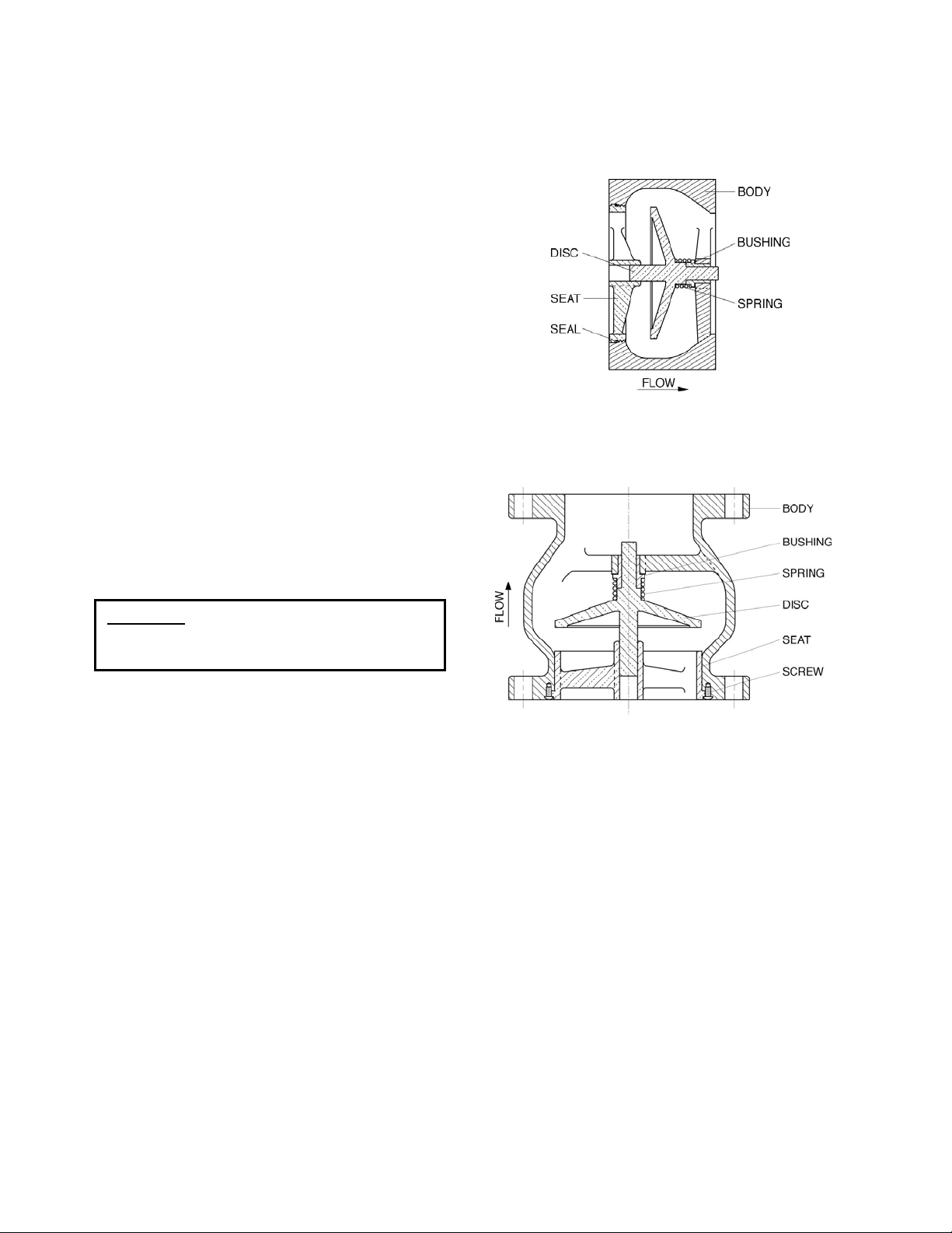
DESCRIPTION OF OPERATION
The silent check valve is designed to prevent
reverse flow automatically. On pump start-up, the
flow of water enters the valve from the seat end (left
side in Figure 1) and forces the disc open, allowing
the passage of fluid through the valve.
Wafer Style
Globe Style
IGURE 1. SILENT CHECK VALVES
F
n pump shut-down, the spring closes the disc
O
efore a flow reversal takes place. This type of
b
losure, which prevents flow reversal, is the factor
c
hich allows “silent” operation and prevents water
w
ammer associated with check valve slam.
h
he valve body is supplied with either compact
T
afer ends as shown in Figure 1 for installation
w
etween mating in a flanged
b flanges or
onfiguration, Figure
The only moving parts in the valve are
pring. The body bushing controls the movement of
s
the plug and assures that the plug contacts the seat
evenly. The valve may have an optional resilient
seal for drop tight service.
1
2. c
the plug and
INSTALLATION
The installation of the valve is important for its
proper operation. The flow arrow on the valve body
or nameplate must point in the direction of flow when
the system is in operation. The valve can be
stalled in horizontal oin
up or down. 14 inch and larger valves may require
extra heavy springs for flow down applications;
consult the factory.
Three diameters of straight pipe upstream of the
alve are recommended tv
treams through the valve, which can cause
s
ibration and wear.
v
When installed in ho
does not have a specific upward orientation. The
valve is usually installed so that the nameplate is
visible on the side of the valve for future reference.
MATING FLANGES: The valve should be installed
between standard flat-face flanges per ANSI B16.5
or AWWA C207. For globe style silent check valves,
the installation req
rawing SS-974F on page 3. The mating flange
D
inside diameter must overlap the valve seat to
provide proper seat retention. Flanges or pipes
having an expanded inside diameter (ductile iron or
mortar-lined pipe) ca
e valve. A ring flange having the maximum inside
th
diameter shown on the drawing must be inserted
between the valve and mortar-lined pipe. The
threaded seat wafer style silent check valves do not
require the mating flange to overlap the seat.
CAUTION: Mating flanges must be flat faced
WARNING: Flanges having an expanded
GASKETS AND BOLTING: The ring-type flange
asket can be rubber or compressed fiber but g
should
d o t
iameters sh wn in Drawing SS-974F. The gaske
must overlap eat to
provide a seal between the seat and the body.
langed valves with ring gaskets should use ASTM
F
A307 Grade B or SAE Grade 2 Carbon Steel bolts.
Higher strength bolts should only be used with fullface gaskets.
be a maximum of 1/16" thick with the
r vertical lines with the flow
o prevent turbulent flow
rizontal lines, the check valve
uirements are illustrated in
nnot be used on the inlet side of
or damage to the valve may
result.
inside diameter such as mortarlined pipe cannot be used on the
inlet side of the valve or damage
may occur. Seat support rings
are needed.
the bronze or stainless steel s
A A valve
DJACENT V LVES: When mating the check
with butterfly isolation valves, the clearance between
the butterfly d e
stem must be s
also shown on .
isc and the fully open check valv
checked. The location of the stem i
the check valve submittal drawings
10 inch and smaller flanged end check valves have
sufficient clearance for most butterfly valves.
However, on 12 inch and larger valves, the plug
shaft extends beyond the flange face and may
interfere with the operation of adjacent valves. A
short run of pipe or spacer may be needed between
the check valve and the isolation valve.
INSTALLATION: Lower valve over mating flange
using slings or chains around the valve body.
Lubricate the flange bolts or studs and insert them
around the flange. Lightly turn bolts until gaps are
eliminated. The
tightening of the bolts should then
be done in graduated steps using the crossover
tightening method. Recommended lubricated
torques for use with resilient gaskets (75 durometer)
are given in Table 1.
If leakage occurs, allow gaskets to absorb fluid and
check torque and leakage after 24 hours. Do not
exceed bolt rating or crush gasket more than 50 per
cent of its thickness.
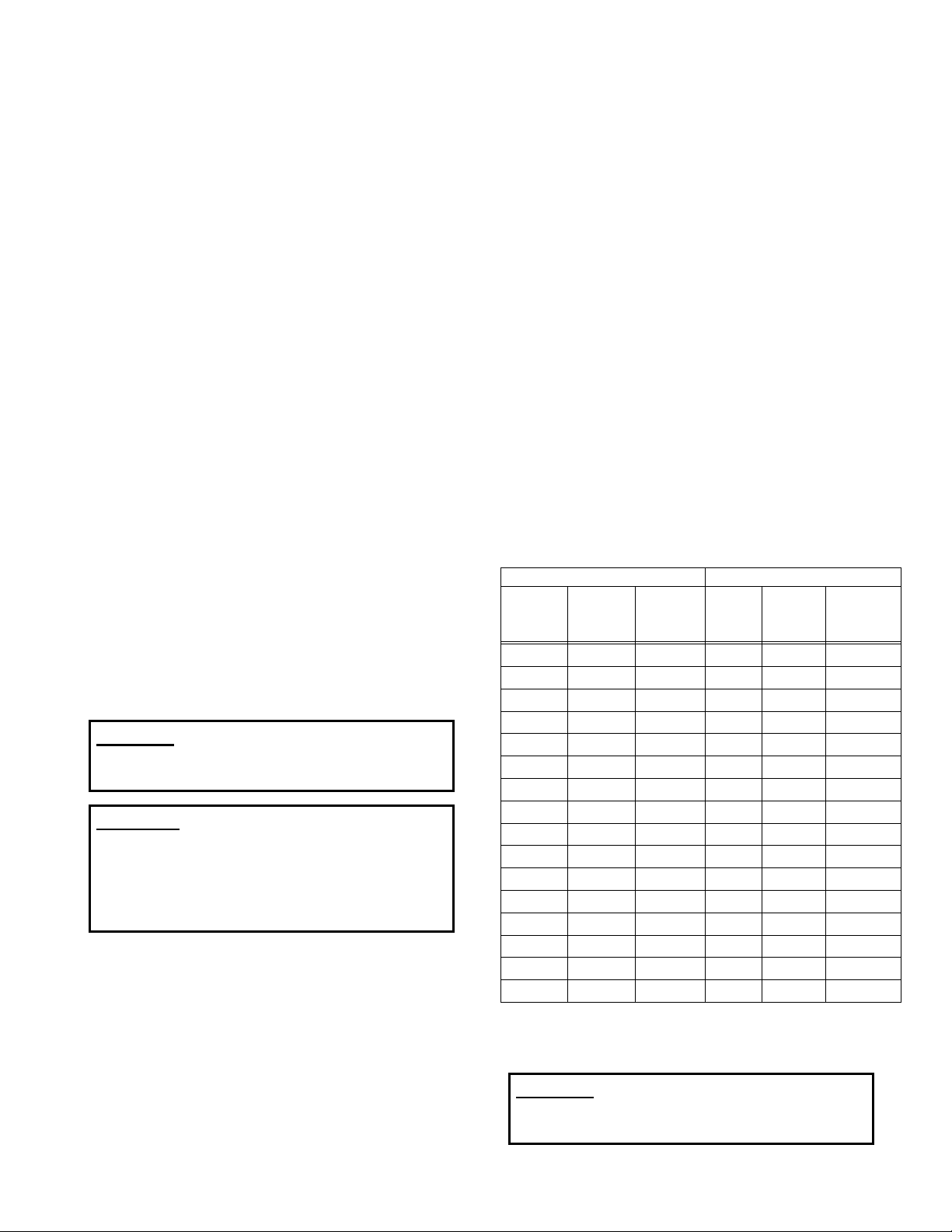
125# FLANGE DATA 250# FLANGE DATA
Valve
Size
(in) (in) (ft-lbs) (in)
2.5 5/8
3 5/8
4 5/8
5 3/4
6 3/4
8 3/4
10 7/8
12 7/8
14 1
16 1
18 1 1/8
20 1 1/8
24 1 1/4
30 1 1/4
36 1 1/2
42 1
Bolt
Dia.
1/2 42 2
Bolt
Torque
25-75
25-75
30-90
30-90
30-90
40-120
45-150
65-200
80-250
90-300
100-350
120-450
150-500
180-600
250-750
300-900
Valve
Size
Bolt
D
ia.
(in)
2.5 3/4
3 3/4
4 3/4
5 3/4
6 3/4
8 7/8
10 1
12 1 1/8
14 1 1/8
16 1 1/4
18 1 1/4
20 1 1/4
24 1 1/2
30 1 3/4
36 2
Bolt
Torque
(ft-lbs)
25-75
35-75
50-150
70-150
70-150
90-200
110-300
160-450
140-450
180-600
190-600
220-600
350-900
500-1500
700-2000
800-2500
TABLE 1. FLANGE BOLT TORQUES
C TIONAU : The u raise face es
se of d- flang or
xce olt que m
e ssive b tor ay
am e es.
d age valv flang
2

3
3

FIGURE 3. GLOBE STYLE CHECK VALVE
VALVE CONSTRUCTION
The standard check valve body (1) is constructed of
iron. See the specific Materials List submitted for
the order if other than standard iron construction.
The internal metal components are bronze or
stainless steel. The disc (3) and spring (4) are the
only moving parts and require no maintenance or
lubrication. The general details of construction are
illustrated in Figures 2 and 3.
The body (1) is either compact wafer style to fit
between two pipe flanges or flanged style for
connection to two pipe flanges. The globe style
valve seat (2) is retained in the body (1) with screws
(6) to allow assembly in the pipeline. The wafer
style valve seat and the 2-1/2” globe style seat are
threaded seats where no seat screws (6) are used.
The seat screws will not retain the seat against full
pressure. The mating flange must properly retain
the seat. Do not remove the upstream flange while
the pipeline is full of water or the seat (2) may
become dislodged from the body.
WARNING: Removal of mating flanges
without draining the pipeline may
cause injury or damage to the
valve.
FIGURE 4. WAFER STYLE CHECK VALVE
ITEM DESCRIPTION MATERIAL
1 Body Cast Iron
2 Seat
3 Disc
(Optional Resilient)
4 Spring
5 Bushing
2
6
Screw1 Stainless Steel
3
O-Ring1 EPDM
6
1. Recommended Spare Part
2. Globe style valve
3. Wafer style valve
1
Bronze or SS
1
Bronze or SS
1
Stainless Steel
1
Bronze
TABLE 2. CHECK VALVE PARTS LIST
MAINTENANCE
Silent Check Valves require no scheduled lubrication
or maintenance.
INSPECTION: Periodic inspection for leakage can
be performed by listening for leakage noise from the
valve while the pump is shut down. If leakage is
heard, drain the pipeline, remove the valve, and
inspect the seating surfaces for wear or mineral
deposits. Clean, lap, or repair trim as needed.
4

TROUBLESHOOTING
Several problems and solutions are presented below
to assist you in trouble shooting the valve assembly
in an efficient manner.
•
Valve Chatters or Vibrates: Verify that velocity is
at least 4 feet per second. Noise sounding like
rocks in the line can be cavitation due to high
velocities, low downstream pressure, or an
upstream expanded. Verify that there are three
diameters of straight pipe upstream.
•
Valve Leakage: Check upstream gasket and
flange to verify that inside diameter meets the
maximum “A” dimension given in Drawing SS-974.
Drain line, remove valve, and inspect seating
surfaces. If seat (2) is lifted above flange
then mating flange and gasket are not securing
the seat properly.
Valve Does Not Pass Flow: Check flow arrow
•
direction on valve body. Verify that downstream
isolation valve is open and there is no line
blockage downstream.
Valve Slams: Remove valve and inspect spring.
•
Heavier springs can be furnished for severe highhead applications. Consult factory if the valve is
installed in a vertical pipe with the flow downward.
face,
DISASSEMBLY
The valve should be removed from the pipeline for
disassembly. A skilled mechanic with proper tools
should perform all work on the valve. Refer to
Figure 2 or 3.
WARNING: The line must be drained before
removing the valve or pressure
may be released causing injury.
1. Lay valve on flat surface or bench with the
arrow facing down. 12” and larger valves require
support for th
2x4 board across the seat (2) and secure with Cclamps to th flange. For the globe style
valve, remove the seat retaining screws (6) and
seat (2). For the wafer style valve and 2-1/2”
globe style valve, unthread the seat (2) from the
body (2) in a counterclockwise direction.
2. For the globe style valves, examine narrow flange
on the outside diameter of the seat (2). The
retaining screws should have left a shallow dimple.
If a deep depression is present, the gasket and
flange internal diameters should be checked to
verify that they are greater than “A” on drawing
SS-974.
e spring during disassembly. Place a
e valve
flow
3. Flip the seat (2) over and inspect the seating
surface. Some minor dents and discoloration are
normal. Grooves or wear areas will cause leakage
and requires seat replacement. Note: Replace
seat if the optional resilient seat o-ring is worn or
damaged.
4. Lift disc (3) from body. Inspect shafts and seating
surfaces for wear. The shaft diameter is normally
about 1/32” smaller in diameter than the hole in
the seat (2) and bushing (5). Some minor dents
and discoloration are normal. Wear areas will
cause leakage and require seat replacement.
Heavy mineral deposits should be removed with
lapping compound or fine sand paper.
5. Remove spring (4) and check for wear or cracks.
6. Remove bushing (5) and inspect for wear. The
inside diameter of the bushing should be about
1/32” larger in diameter than the shaft.
REAS MBLY
b cleaned with a stiff w rush in the direc
1 Insert bushing (5 into body (1). The bushing is )
2. Lay spring (4) and disc (3) over bushing (5).
3 stall seat (2) with the ret
4. Install new gaskets and valve. Tighten flange
SE
ll parts ust be clean and gasket surfacA
e ire b tion of
a als should during
.
. In aining screws (6). 12”
m es should
e hine parts,
serrations r mac marks. Worn th o
skets, and e be replacedg s
a
ssembly. re
r
e ined by the pring. ta s
an y require a 2x4 board and C-
d larger valves ma
clamps to compress the spring into the body. For
the the
thread seat valves, tighten the seats to
follo
wing values:
Threaded Seat Torque
Valve Size Torque
2”-3” 25 ft-lbs
4”-10” 50 ft-lbs
bolts evenly using the crossover tightening method
and the torque values given in Table 1 on page 2.
5

t
t
Y
PARTS AND SERVICE
Parts and service are available from your local
representative or the factory. Make note of the
Valve Size and Model
ameplate and contact:
n
Val-Matic Valve and Manufacturing Corp.
905 Riverside Drive
Elmhurst, IL 60126
Phone: (630) 941-7600
Fax: (630) 941-8042
www.valmatic.com
sales representative will quote prices for parts or
A
rrange for service as needed.
a
Number located on the valve
LIMITE
D WA
All products are warranted t
shipment, subject to the limitations below.
If the purchaser believes a product is defective, the purchase
permission to return the product; (b) if permission is given, re
for return and found to be defective, the manufacturer will, at
60 days of receipt, or refund the purchase price. Other tha
manufacturer shall not be liable for any loss, costs, expenses or damages of any kind arising out of the product, its use, installation
or replacement, label
warnings or lack of an
WARRANTIES OF FITNESS FOR A PARTICULAR PURP
AFFIRMATION OF FACT, PROMISE, DESCRIPTION OF PRODU
FROM MANUFACTURER, UNLESS SIGNED BY THE PRESIDE
sold or intended for personal, family or household purposes.
o be free of defects in material and workm
n to repair, replace or refund as described above, purchaser agrees tha
ing, instructions, information or technical da l,
y of the foregoing. NO OTHER WARRA
RRANTY
anship for a period of one year from the date of
r shall:
(a) Notify the manufacturer, state the alleged defect and reques
turn th
e product with transportation prepaid. If the product is accepted
his dis
cretion, either repair or replace the product, f.o.b. factory, within
ta of any kind, description of product use, sample or mode
NTIES, SS OR IMPLIED, INCLUDING THE
OSE A D E MADE OR AUTHORIZED. NO
CT OF USE OR SA RRANT
NT OF factured,
WRITTEN OR ORAL, EXPRE
MERCHANTABILITY, AR
N
THE MANUFACTURER. These products are not manu
MPLE OR MODEL SHALL CREATE ANY WA
®
MATIC VALVE AND MANUFACTURING CORP.
VAL-
905
TEL.
®
RIVE IDE DR. ELMHURST, IL. 60126
RS
630 41-7600 FAX. 630 / 941-8042
/ 9
6
 Loading...