


Manual No.
TDCV-OM1-4
Val-Matic®
®
Tilted Disc
Check Valve
Operation, Maintenance and
Installation Manual
INTRODUCTION ............................................... 1
RECEIVING AND STORAGE ........................... 1
DESCRIPTION OF OPERATION ...................... 1
INSTALLATION ................................................ 2
VALVE CONSTRUCTION ................................. 3
MAINTENANCE ................................................ 4
TROUBLESHOOTING ...................................... 4
DISASSEMBLY ................................................. 5
REASSEMBLY .................................................. 5
OPTIONAL BMOD ............................................ 8
OPTIONAL TMOD ............................................ 11
OPTIONAL BYPASS ......................................... 15
PARTS AND SERVICE ..................................... 15
WARRANTY ..................................................... 16
VAL-MATIC
905 Riverside Dr. ● Elmhurst, IL 60126
Phone (630) 941-7600 ● Fax (630) 941-8042
www.valmatic.com
®
VALVE AND MANUFACTURING CORP.
TILTED DISC® CHECK VALVE
OPERATION, MAINTENANCE AND INSTALLATION
INTRODUCTION
This manual will provide you with the information to
properly install and maintain the check valve to
ensure a long service life. The Tilted Disc Check
Valve is ruggedly constructed with aluminum-bronze
or stainless steel trim to give years of trouble free
operation. The valve should be installed in water
pipelines three diameters downstream of pumps to
prevent reverse flow.
For valves with Top Mounted Dashpots, DO
NOT paint exposed surfaces of the
connecting rod or the cylinder piston rod or
damage will result to the hydraulic seals.
The valve is designed to open after pump start and
allow water to flow through the pipeline or water
main while creating a minimal amount of headloss.
A top or bottom mounted oil dashpot may be
included to control the opening and closing of the
valve. The valve size, cold working pressure, and
model number are stamped on the nameplate for
reference.
This valve is not intended for fluids containing
suspended solids such as wastewater. For
wastewater and other high turbidity applications, use
Val-Matic Series 500 Swing-Flex
The Tilted Disc Check Valve is not intended
for use with sewage or fuel service.
RECEIVING AND STORAGE
Inspect valves upon receipt for damage in shipment.
Unload all valves carefully to the ground without
dropping. When lifting, the valve should be lifted
with straps or bolts in the flange holes. The valve
should never be lifted by the dashpot assembly.
The valves should remain crated, clean and dry until
installed to prevent weather related damage. For
long-term storage greater than six months, the
valves should be stored indoors or the ends of the
valve should be sealed with plastic wrap to prevent
weather related damage.
CAUTION
CAUTION
Check Valve.
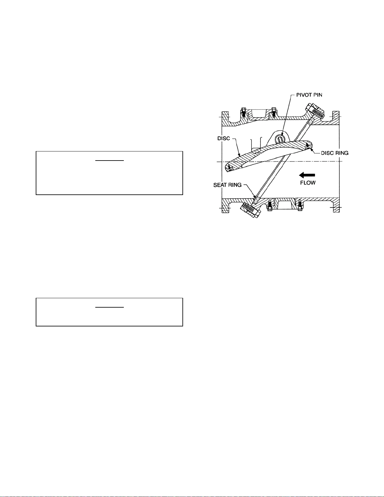
FIGURE 1. Tilted Disc
Check Valve
DESCRIPTION OF OPERATION
The Tilted Disc Check Valve consists of two body
sections bolted together at a central 55-degree
diagonal flange assembly, forming a single valve
body. The inlet body section contains a seat ring
positioned and captured by the diagonal flanges.
The outlet section contains two eccentrically located
pivot pins from which a disc, containing a beveled
disc ring, pivots 40 degrees from the closed to the
fully open position.
The location of the eccentric pivot trunnions allows
the seating surface of the disc ring to rotate away
from the seating surface of the seat ring, without
contact, when the valve opens. Conversely, during
closing the seating surface of the disc ring moves
into the seating surface of the seat ring without
contact, until final sealing contact is made. A small
amount of clearance exists between the pivot pin
and the pivot pin bushing when the disc ring makes
full contact with the seat ring to ensure a tight seal.
The flow area throughout the valve equals or
exceeds the flow area of the pipe, thus minimizing
the head loss through the valve.
1
DESCRIPTION OF OPERATION (cont’d)
p
Upon pump start-up, the forward flow of water will
start to rotate the disc about the pivot pins until the
disc rotates through a 40-degree arc and contacts
the integral body stops. The partially balanced disc
assists in opening the disc and stabilizes the disc in
low-flow cases where the valve remains partially
open.
On pump shutdown, the forward velocity of the water
starts to diminish, until the disc is no longer held
against the body stops and the partially balanced
disc will move to the closed position. When the
forward velocity reaches zero, the disc will have
moved to the closed position and the reversal of flow
is checked. The 40-degree travel of the disc and the
partially balanced disc reduces the potential for
check valve slam and water hammer normally
associated with conventional swing check valves.
However, ideal hydraulic conditions are not always
predictable and the potential for water hammer can
still exist. Applications with a potential for valve slam
include high-head pumping, multiple high service
pumps, and the use of hydro-pneumatic surge tanks.
If the reversal of flow occurs before the disc has a
chance to fully close, it will be driven to the closed
position by the rapid flow reversal.
For these rapid flow reversal conditions, a bottom
mounted hydraulic dashpot can be fitted in the
bottom inspection port, provided that sufficient
clearance is provided for installation. The bottom
mounted oil dashpot will control the last 10 degrees
of disc travel between 1 and 5 seconds. A top
mounted dashpot can also be used. A top mounted
oil dashpot performs the same function as a bottom
dashpot and in addition, independently controls the
full open and closing strokes between 5 and 30
seconds to prevent line surges.
INSTALLATION
The installation of the valve is important for its
proper operation. The Tilted Disc Check Valve can
only be used for horizontal flow or vertical flow-up
applications.
For horizontal flow applications, the valve must
be installed with both of the eccentric pivot pin
trunnions located above the horizontal
centerline of the valve and they must be level
to the horizontal
Each valve is provided with a flow arrow integrally
cast on the valve body and a flow arrow printed on
the metal label attached to the valve. These flow
arrows must point in the direction the water will flow,
when the system is operating. ANSI Class 125 and
Class 250 Cast Iron valves are furnished with flat
CAUTION
lane of the valve.
faced flanges and should be mated with flat faced
companion flanges. The valve and adjacent piping
must be supported and aligned to prevent
cantilevered stress being transferred to the valve’s
flanges when installing the flange bolts or studs. For
raised face applications, a ductile iron valve body
should be specified.
CAUTION
The valve must be mated with flat-faced
flanges or damage may result. The use of
excessive bolt torque can damage the valve.
When mating the check valve with butterfly isolation
valves, the clearance between the butterfly disc and
the fully open check valve stem must be checked. A
spacer pipe is sometimes needed. See the valve
arrangement drawing for disc clearance dimensions.
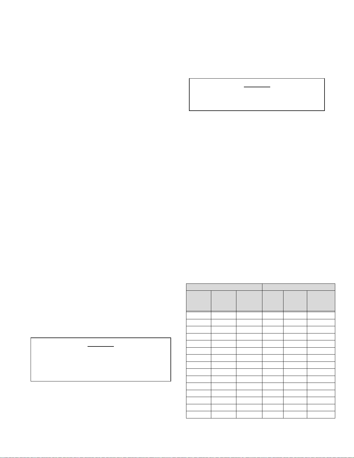
FLANGED ENDS: The flange should be mated with
flat-faced pipe flanges equipped with resilient
gaskets. When ring gaskets are used, the bolt
material shall be ASTM A307 Grade B or SAE
Grade 2 Carbon Steel. Higher strength bolts should
only be used with full-face gaskets.
INSTALLATION: Lower valve into the pipeline using
slings or chains around the valve body. Eye bolts or
bars can also be used in the bolt holes. Lubricate
the flange bolts and insert them around the flange.
Lightly turn bolts until gaps are eliminated. The
tightening of the bolts should then be done in
graduated steps using the cross-over tightening
method. Recommended lubricated torques for use
with resilient gaskets (75 durometer) is given in
Table 1. Do not exceed bolt rating or crush gasket
more than 50 percent of its thickness.
125# FLANGE DATA 250# FLANGE DATA
Valve
Size
(in)
4 5/8 30-90 4 3/4 50-150
6 3/4 30-90 6 3/4 70-150
8 3/4 40-120 8 7/8 90-200
10 7/8 45-150 10 1 110-300
12 7/8 65-200 12 1 1/8 160-450
14 1 80-250 14 1 1/8 140-450
16 1 90-300 16 1 1/4 180-600
18 1 1/8 100-350 18 1 1/4 190-600
20 1 1/8 120-450 20 1 1/4 220-600
24 1 1/4 150-500 24 1 1/2 350-900
30 1 1/4 180-600 30 1 3/4 500-1500
36 1 1/2 250-750 36 2 700-2000
42 1 1/2 300-900 42 2 800-2500
48 1 1/2 400-900 48 2 900-1800
54 1 3/4 400-1200 - - -
Bolt
Dia.
(in)
Bolt
Torque
(ft-lbs)
Valve
Size
(in)
Bolt
Dia.
(in)
Bolt
Torque
(ft-lbs)
TABLE 1. Flange Bolt Torques
2
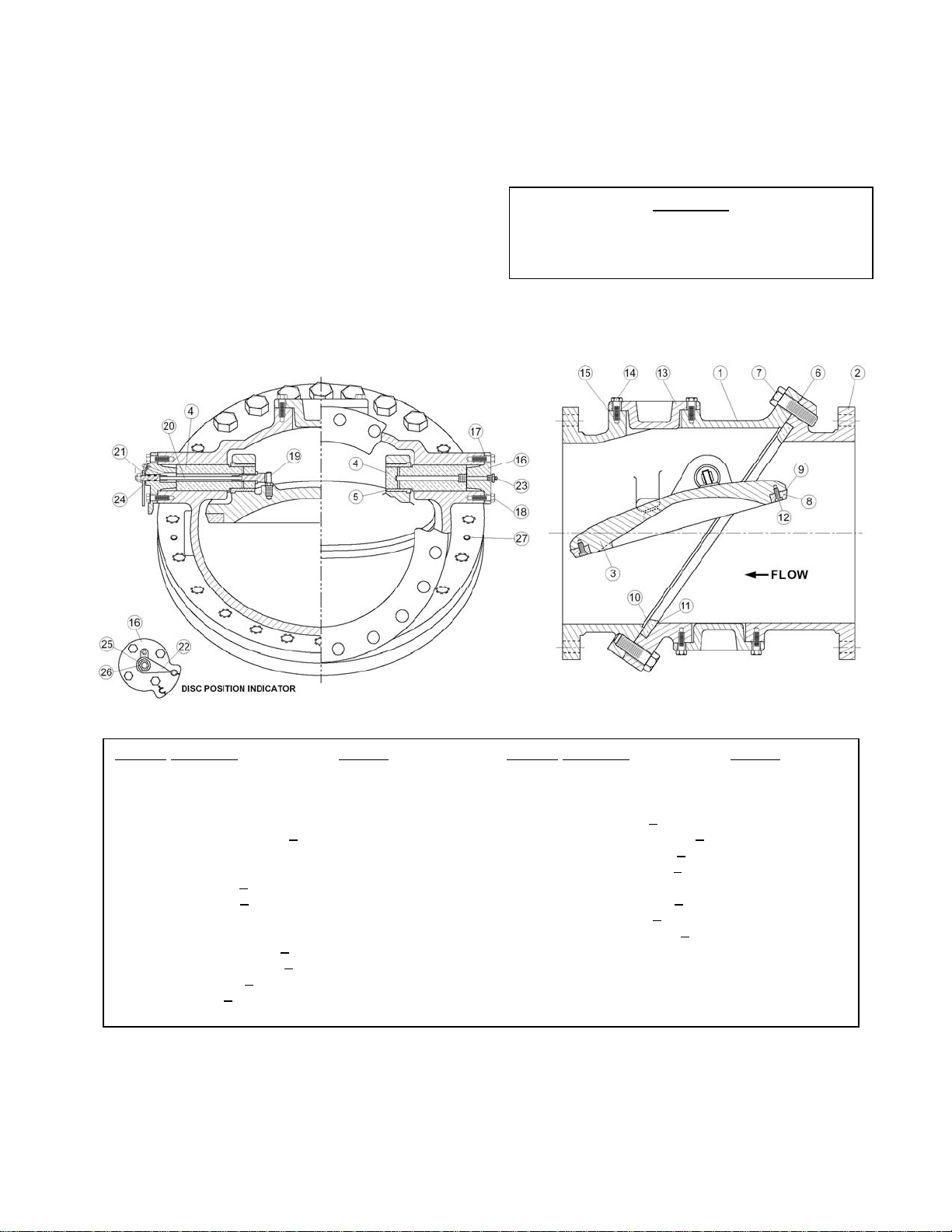
VALVE CONSTRUCTION
The standard Tilted Disc Check valve is ruggedly
constructed of cast iron. See the specific Materials
List submitted for the order if other than standard
iron construction. The internal metal components
are aluminum bronze or stainless steel. The pivot
pins (4) are fixed in the body (1) and support the
disc (3). Grease fittings (23) are provided to allow
regular lubrication of the pivot pin. The general
details of construction are illustrated in Figure 2.
The body is flanged to connect to a pipe flange. The
body consists of a pivot body half (1) and a seat
pivot half (2). The seat (11) is held in place by the
two body halves. Top and bottom inspection hole
covers (13) are provided for servicing the valves and
to allow installation of dashpots. Do not remove the
inspection covers while the pipeline is under
pressure or the cover may release pressure
suddenly.
Removal of inspection covers without draining
the pipeline and valve may cause serious
injury.
WARNING
Figure 2. Basic Valve Construction
Part No. Part Name Material Part No. Part Name Material
1 Pivot Body Half Cast or Ductile Iron 16 Pivot Pin Cover Cast Iron
2 Seat Body Half Cast or Ductile Iron 17* Pivot Pin Cover Gasket Non-Asbestos
3 Disc Cast or Ductile Iron 18 Pivot Pin Cover Bolt Alloy Steel
4* Pivot Pin Alum. Brz. 19 Indicator Pin (>6”) Stainless Steel
5* Pivot Pin Bushing (>12”) Alum. Brz. 20 Indicator Shaft Assy (>6”) Stainless Steel
6* Body Seal Buna-N 21 Indicator Washer (>6”) Stainless Steel
7 Body Flange Bolt Alloy Steel 22 Indicator Pointer (>6”) Carbon Steel
8 Disc Ring (>12”) Alum. Brz. 23* Grease Fitting Stainless Steel
9 Ring Seal (>12”) Buna-N 24* Indicator O-rings (>6”) Buna-N
10 Seat Ring Alum. Brz. 25 Lock Washer (>6”) Stainless Steel
11 Seat Ring Seal Buna-N 26 Indicator Jam Nut (>6”) Stainless Steel
12 Ring Ret. Screw (>12”) Stainless Steel 27 Locating Pins Plated Steel
13 Inspection Cover (>6”) Cast Iron
14 Cover Bolt (>6”) Alloy Steel
15* Gasket (>6”) Non-Asbestos
*Recommended Spare Part
3
MAINTENANCE
The operation of the valve can be seen by observing
the movement of the indicator pointer on the side of
the valve (6” and larger sizes). The valve should
move about 40 degrees from the closed to the fully
open position. It is normal for the valve to not fully
open in cases where the fluid velocity is less than 8
ft/sec or a Top Mounted Oil Dashpot is installed.
Dashpot assemblies require regular maintenance.
See the dashpot section in this manual.
LUBRICATION: The Tilted Disc Check Valve is
provided with grease fittings (23) located on the
pivot pin covers. The valve’s pivot trunnions must
be lubricated at least monthly or as conditions
dictate with a waterproof, FDA or ANSI/NSF 61
approved grease such as Lubriko #CW-606 (Master
Lubricants Co., Philadelphia, Pa). Using a cartridge
grease gun, pump grease into each grease fitting
using 8 full strokes of the grease gun lever.
INSPECTION: Periodic inspection for leakage can
be performed by placing a listening device or an ear
on the valve while it is closed and the line is under
pressure. If leakage is heard, close the isolation
valve and drain the valve connection, and inspect
the seating surfaces for wear or mineral deposits.
Clean or repair trim as needed.
Removal of inspection covers without draining
the pipeline and valve may cause serious
injury.
The inspection hole covers can be removed from the
valve to facilitate internal inspection of the valve. A
hoist or jacking mechanism should be used to lift the
disc to inspect the seating surfaces. If replacement
of the disc, pivot pin bushings, disc ring, or seat ring
is required, the valve must first be removed from the
line.
WARNING
TROUBLESHOOTING
Several problems and solutions are presented below
to assist you in trouble shooting the valve assembly
in an efficient manner.
TROUBLESHOOTING BASIC VALVE: The valve
opens automatically without the need of a power
source to allow forward flow. The valve may not
open to the full open position depending on fluid
velocity but it will always open far enough to pass
the flow with a minimal headloss. The valve will
automatically close to prevent reverse flow through
the pump. The valve has metal seats and a
moderate bang during closing is normal.
1. Leakage at Valve Inspection Covers (13): Retighten bolts evenly or replace non-asbestos
sheet gasket.
2. Leakage at Grease fitting: Inject grease or
replace grease fitting (23).
3. Leakage at Mating Flanges: Re-tighten bolts
using the cross-over method or replace mating
flange gasket. Flange gaskets are typically 70
durometer resilient material. Check alignment
of mating pipe.
4. Valve Leaks when Closed: Flush debris from
seat by cycling valve. Verify that valve is subject
to a minimum differential pressure of at least 10
psi when closed and the isolation butterfly or
gate valve is open. If leakage persists, inspect
interior of valve. Clean seating surfaces. When
used with a power operated control valve, there
may not be sufficient reverse flow to seat the
valve. These types of installations require a
power outage for proper valve seating so that
the pump is tripped while the control valve is
open.
5. Valve Fails to Open: Check pressure differential
across disc; upstream pressure must be greater
than downstream pressure. Verify that the
suction and discharge shutoff valves are open
and there is no line blockage. Drain pipe on
both sides of the valve, remove inspection cover
(13), and inspect disc ring (8) and seat ring (10)
for damage or wedged debris.
6. Noisy Operation: Flow noise is normal. Loud
flow noise similar to hammering may be
cavitation from dropping high pressures across
valve; review flow velocity through valve and
pump application.
4

DISASSEMBLY OF BASIC VALVE
The valve should be removed from the pipeline for
disassembly. All work on the valve should be
performed by a skilled mechanic with proper tools.
Refer to Figure 2.
The line must be drained before removing the
valve or pressure may be released causing
injury.
WARNING
1. Lay valve on flat surface or bench with the inlet
flange face down.
2. Using a flat-nosed punch, drive out the two
locating pins (27).
3. Remove the indicator jam nut (26), lockwasher
(25), pointer (22), pivot pin cover bolts (18) and
covers (16).
4. Remove the pivot pins (4). The end of the pin is
tapped for insertion of a 9/16”-18 or 3/4”-16
threaded rod.
5. Attach a hoist to the outer flange of the valve to
support the weight of the outlet body section of
the valve and remove the diagonal flange bolts
(7).
6. Using the hoist, raise the outlet body section of
the valve. If the valve sections are joined tightly
by the gasket, lift the valve 1/8” and hammer the
inlet body section down with a soft-blow hammer
or block of wood. Once the body sections are
separated, raise the outlet section to clear the
disc pivot trunnions and place the outlet section
on a wooden skid.
7. Remove the pivot pin bushings (5) from the disc
pivot trunnions on 12” and larger valves. They
may be set in place with sealant so apply heat to
the disc trunnions with a propane torch to soften
the Loctite if necessary.
8. Thread an eye bolt into one of the threaded holes
in the disc’s rectangular pad. Using a nylon sling
through the disc trunnions and eye bolt, lift the
disc straight up while maintaining its 55 degree
tilt.
9. Place the disc on a wooden skid and using the
nylon sling through just the eye bolt, turn the disc
over with the disc ring (8) facing up.
All parts can now be easily inspected for wear or
damage and replacement parts can be ordered as
needed. If replacing the seat (10) or disc ring (8), it
is recommended that they be replaced as a set. The
pivot pins (4) should fit tightly in the body, but there
should be ample clearance (at least 1/32”) between
the pins (4) and the bushings (5).
REASSEMBLY OF BASIC VALVE
All parts must be clean and gasket surfaces should
be cleaned with a stiff wire brush in the direction of
the serrations or machine marks. Worn parts,
gaskets, and seals should be replaced during
reassembly.
1. Place the seat body half (2), with the inlet flange
face down on a wooden skid.
2. Install a lightly lubricated seat ring seal (11) in the
register of the seat body half.
3. Install the seat ring (10) with the serrated surface
toward the seal, into the register of the body seat
half.
4. With the disc on a wooden skid, and the disc ring
register up, place a lightly lubricated disc ring
seal (9) onto the disc register.
5. Assemble the disc ring with the serrated face
toward the seal.
6. Place a small amount of Loctite thread locking
compound on each of the retaining screws (12)
and thread them into the tapped holes in the disc.
Tighten them initially hand tight and then using
the cross-over tightening method, torque each
screw in graduated steps, according to the
following chart.
Valve Sizes Torque
12” to 14” 13 ft-lbs
16” to 24” 20 ft-lbs
30” 28 ft-lbs
36” and larger 40 ft-lbs
7. Thread in eye bolt into one of the threaded holes
in the disc’s rectangular pad. Insert a nylon sling
through the eye bolt and attach the loops of the
sling to the hook of a hoist. Carefully turn over
the disc, using the hoist, making sure that the
beveled seating surface of the disc ring does not
make contact with metal or hard surfaces.
8. Install the pivot pin bushings into the disc pivot
trunnions with Loctite 680.
9. Remove the nylon sling from the eye bolt and
place it through the disc’s pivot trunnions bores
and attach the loops of the sling to the hoist.
Attach a short chain from the hoist’s hook to the
eyebolt and adjust the length of the chain to keep
the disc at a 55 degree angle when housing the
disc.
5

REASSEMBLY OF VALVE (Cont’d)
10. Slowly lower the disc into the beveled seat ring,
using care not to drop or allow the disc to swing
into the seat ring. After the disc is in place,
carefully align the disc’s pivot trunnions, so they
are at equal distance from the diagonal flange
locating pin holes and that the disc ring is parallel
to the seat ring.
11. Lightly lubricate and install the diagonal flange
gasket or O-ring seal (after 2013) on the face of
the seat body half diagonal flange and align the
holes in the gasket with the holes in the flange.
The two small holes must be aligned with the two
locating pin holes (27).
12. Install two temporary slip-fit locating pins into the
seat body half’s diagonal flange. Hoist the pivot
body half over the seat body half and lower the
diagonal flange with 1/2” of the mating flange.
Align the locating pin holes (27). Once the
diagonal flanges are aligned, the pivot body half
can be lowered.
13. Apply a lubricant to the flange bolt threads (7).
Once all of the diagonal flange bolts are inserted,
tighten them hand tight. The torquing of the
diagonal flange bolts should then be done in
three graduated steps using the cross-over
tightening method to load the bolts evenly.
14. Remove the temporary slip-fit locating pins from
the diagonal flange and install the permanent
locating pins (27).
15. Insert the indicator shaft assembly (20) through
the 9/16” diameter hole in the indicator pivot pin
(19) and insert the assembly into the body
trunnions bore. Align the slot in the indicator pin,
which is threaded into the disc. Install the pivot
pin into the opposite trunnions bore.
16. Install the two indicator o-ring seals into the
grooves of the indicator shaft. Make sure that the
seals are not twisted within the grooves. Apply
some grease on the seals. Lightly lubricate the
pivot pin cover gasket and place it on the
machined face of the indicator pin cover (16) and
install the cover (16) over the indicator shaft.
Insert the pivot pin cover bolts (18) and tighten
hand tight. The torquing of the bolts should be
done in two graduated steps using the cross-over
tightening method to load the bolts evenly.
17. Install the external indicator washer (21) over the
indicator shaft. Place the indicator pointer (22)
on the end of the indicator shaft. The pointer
should point toward the letter “C” cast on the
indicator pivot pin cover. Slip the indicator
lockwasher (25) and jam nut (26) while holding
the indicator pointer. Do not over-tighten.
18. Lightly lubricate the opposite pivot pin cover
gasket (17) and place it on the machined face of
the pivot pin cover (16) and install the cover to
the other pivot body half’s trunnions boss. Insert
the pivot pin cover bolts (18) and tighten hand
tight. The torquing of the bolts should be done in
two graduated steps using the cross-over
tightening method to load the bolts evenly.
19. Lightly lubricate the inspection hole gasket (15)
on the machined face of the inspection hole cover
(13) and install the cover to the inspection hole
port located on each body half. Insert the cover
bolts (14) and tighten hand tight. The torquing of
the bolts should be done in two graduated steps
using the cross-over tightening method to load
the bolts evenly.
20. The pivot trunnions must be lubricated with a
waterproof, FDA approved grease, as outlined in
the maintenance section. Install grease fittings
(23) and pump grease into each fitting until the
grease is observed at the interface of the pivot
pin bushing’s inside diameter (5) and the pivot
pin’s outside diameter (4).
21. Operate the valve several times, with the use of a
hoist, to ensure correct operation before reinstalling the valve.
6

OPTIONAL BOTTOM DASHPOT
DESCRIPTION: The Bottom Mounted Oil Dashpot
(BMOD), when required, is installed in the bottom
inspection port of the Tilted Disc Check Valve. This
unit provides control of the disc’s final 10% of travel
to the close position to reduce water hammer
normally associated with rapid flow reversal
conditions that exist on pump shut down. The unit
consists of a high-pressure hydraulic cylinder,
adjustable flow control valve, pressurized oil
reservoir and piping.
A dashpot spacer which provides an air gap,
connects the hydraulic cylinder and the dashpot
cover, to prevent pressurized hydraulic fluid from
entering the valve housing and contaminating the
water system. The dashpot cover contains a
snubber rod bushing and snubber rod which
contacts the disc and the spring retainer assembly
that is attached to the piston rod of the hydraulic
cylinder.
OPERATION: Upon start-up, the forward flow of the
water will open the check valve. The snubber rod is
extended by the piston spring and the pressurized
hydraulic fluid in the cylinder. On pump shutdown,
the reversal of flow will close the check valve. Prior
to the valve fully closing, the disc will make contact
with the snubber rod and the hydraulic fluid will
slowly bleed through the adjustable flow control
valve, thus allowing the disc to move slowly into the
seat. Some reverse flow and pump backspinning
may occur during this process.
INSTALLATION: The BMOD may be installed at the
factory (valves larger than 12”) or it may be installed
in the field as follows.
1. Remove the valve bottom inspection hole cover
(13) and gasket (14).
2. Clean the gasket residue from the face of the
inspection hole port.
3. Place the o-ring (70) into the groove of the
dashpot cover (60).
4. Install the dashpot unit into the inspection hole
port, aligning the snubber rod bushing to the
notch in the inspection hole port.
5. Install the dashpot cover bolts (14) and tighten.
6. Start the unit with the flow control valve (38) in
the full open position (fully counterclockwise).
Figure 3. Bottom Mounted Oil Dashpot
7. The BMOD has been filled with oil at the factory.
Using a bicycle tire pump inject air into the air
fitting (55) until the pressure is 50 psi higher than
the water system pressure on the discharge side
of the check valve. The air pressure acts to
counter-balance the force created by the internal
water pressure acting on the area of the snubber
rod (63). The air pressure and spring (71) work
to extend the snubber rod when the check valve
opens.
8. Start the pump and allow the check valve to fully
open.
9. Shut down the pump and observe the action of
the valve closure. If a slam occurs, the flow
control valve can be gradually turned down
(clockwise), until optimum operation is achieved,
see Figure 9. The BMOD unit is designed to
control the closing time between 1 and 5
seconds.
Flow control valves should not be used at
settings below the blue band (second from the
bottom). Lower settings will allow small
particles of silt present in the hydraulic fluid
to clog the valve and cause the BMOD to bind
and result in damage to the valve or dashpot.
CAUTION
7

OPTIONAL BOTTOM DASHPOT (Cont’d)
It is recommended that the person making
adjustments to the flow control valve be familiar with
the sounds created by water hammer and valve
slam and not confuse them with the metallic sounds
created by the valve upon metal seat closure. An
over control situation should be avoided so that
cavitation (loud rumbling) does not occur. After
setting the flow control valve, tighten the locknut or
set screw on the valve. Record the flow control
valve setting and air pressure for future reference.
Valve Size FCV Setting Air Pressure
CHECKING OIL AND GREASE LEVELS:
1. The check valve should be closed.
2. The air in the oil reservoir must be bled from the
reservoir, using the air valve mounted on the
reservoir.
3. Remove the pipe plug from the oil reservoir fill
port.
4. Add hydraulic fluid equal to Mobil #DTE 24 until
fluid is up to level indicated on the reservoir.
Replace pipe plug.
5. Recharge the reservoir with air pressure to a
minimum of 50 psi over the water line pressure.
6. The grease level can not be checked but it is
recommended that the grease fitting be charged
with grease twice a year. Use a cartridge grease
gun and pump grease into the fitting using two full
strokes. An FDA approved grease such as
Lubriko #CW-606 should be used (Master
Lubricants Company, Philadelphia, PA)
DASHPOT SEAL REPLACEMENT: There are
several seals in the unit that may require
replacement.
TROUBLESHOOTING VALVE WITH BOTTOM
MOUNTED OIL DASHPOT: The bottom mounted oil
dashpot engages the disc for the last 10% of travel
and the flow control valve (38) controls the speed of
closure in the 1-5 second range.
1. Leakage of Oil: Wipe down controls and identify
the location of the leak. Tighten fittings where
needed. Cylinder seal kits can be used if cylinder
leakage persists.
2. Leakage of Air: With a minimum of 50 psi in the
tank, apply soap solution to tank, gauge, and pipe
plug and observe bubbles. Tighten fittings where
needed. Replace gauge or pipe plug using
Loctite PST pipe sealant (allow 4 hrs for full
cure).
3. Valve Does Not Close Fully: Check air pressure
in reservoir; the pressure should be 50 psi over
the water line pressure. Open flow control valve
further to allow greater oil flow. Readjust flow
control valve until slam is diminished. A
differential pressure across of the disc of at least
10 psi is typical for dashpot valves. If the
pressure is lower, the dashpot is probably not
needed and may interfere with valve operation.
Start and stop pump again with the isolation
butterfly or gate valve fully open.
4. Valve Slams Closed: Dashpot should prevent
slamming by controlling the last 10% of valve
closure. Throttle down the flow control valve to
slow down valve closure. If problem persists, the
snubber rod (63) may not be extending. The
extension can be viewed through the 3/8”
diameter drain holes in the dashpot spacer (62).
Apply grease to grease fitting (23) in dashpot.
Increase air pressure in 25 psi increments to 150
psi over line pressure. If problem persists,
remove, disassemble, clean, and install new
seals in dashpot assembly; apply lubricant to
seals and sliding surfaces before installation.
INSTALLING NEW DASHPOT SEALS:
1. Depressurize and drain the valve and pipeline.
2. Remove the dashpot from the valve and remove
the 4 nuts holding the dashpot spacer.
3. Replace the (2) rod wipers (68) and o-ring seals
(66 and 67).
4. If the oil cylinder is leaking oil, tighten the tie rod
nuts. The cylinder should be returned to the
factory for rebuilding if leakage persists.
5. Reinstall and charge the unit with air as listed
above for a new unit.
8

OPTIONAL BOTTOM DASHPOT Cont’d)
FIGURE 4. Bottom Mounted Oil Dashpot (BMOD) Construction
Part No. Part Name Material Part No. Part Name Material
1 Pivot Body Half Cast or Ductile Iron 66* Snubber Rod O-Ring Buna-N
2 Seat Body Half Cast or Ductile Iron 67* Bushing O-Ring Buna-N
3 Disc Cast or Ductile Iron 68* Rod Wiper Molythane
38 Flow Control Valve Brass 69* Retaining Ring Buna-N
54* Pressure Gauge Brass 70* Cover O-Ring Buna-N
55* Air Inlet Valve Stainless Steel 71 Spring Steel (plated)
60 Dashpot Cover Ductile Iron 72 Lower Bushing Bronze
61 Dashpot Cylinder NFPA, Steel 73 Spring Retainer Stainless Steel
62 Dashpot Spacer Ductile Iron 74 Mounting Screw Alloy Steel
63 Snubber Rod Stainless Steel 75 Oil Reservoir Carbon Steel
64 Snubber Rod Bushing Alum Bronze 78 Dashpot Piping Steel
65 Spring Guide Alum. Bronze
*Recommended Spare Part
9

OPTIONAL TOP DASHPOT
DESCRIPTION: The Top Mounted Oil Dashpot
(TMOD), when required, is installed in the top
inspection port of the Tilted Disc Check Valve and is
attached with linkage to the disc. This unit provides
single-stage speed control of valve opening and twostage speed control of valve closing to reduce
pressure surges on pump start-up and shut-down.
The dashpot unit consists of a high-pressure oil
hydraulic cylinder, two adjustable flow control valves,
a pressurized oil reservoir, a non-pressurized oil
reservoir, and piping. A dashpot spacer which
provides an air gap, connects the hydraulic cylinder
and the dashpot cover, to prevent pressurized
hydraulic fluid from entering the valve housing and
contaminating the water system. The dashpot
spacer also contains the connecting rod bushing,
bushing retainer plate and screws, o-ring seals,
external and internal rod wipers, and the connecting
rod which is connected to the piston rod of the
hydraulic cylinder with a special quick coupling
assembly. The connecting rod is attached to the
check valve disc via links and pins.
OPERATION: Upon start-up, the forward flow of the
water will open the check valve. The hydraulic fluid
within the top portion of the dashpot cylinder is
slowly bled through the top external flow control
valve, until the valve travels to the full open position.
On pump shutdown, the reversal of flow will start to
drive the disc to the closed position. For the first
90% of the disc travel, the hydraulic fluid within the
bottom portion of the dashpot cylinder is slowly bled
through the bottom flow control valve. The cylinder’s
internal cushion plunger then enters the cushion
cavity located in the head of the hydraulic cylinder,
provides a finer speed control (second stage) over
the final 10% of disc travel to the closed position.
INSTALLATION: Follow the installation instructions
for the basic valve for installation of the valve in the
line. Use the following steps to start up the TMOD.
1. The external flow control valves should be set in
the full open position (counterclockwise).
2. The cylinder’s internal cushion adjustment screw
in the face of the head is factory set at 4 turns
from being bottomed out, see Figure 6.
3. The dashpot has been filled with oil in the factory
and no additional fluid is required unless external
leakage is observed. (See maintenance section
on how to check fluid level).
4. Using a bicycle pump, charge the pressurized
reservoir until the air pressure equals 20% of the
water pressure on the discharge or downstream
side of the check valve.
Figure 5. Top Mounted Oil Dashpot (TMOD)
5. Start the pump and observe the action of the
valve through the opening cycle and allow the
water system pressure to stabilize.
6. Shut down the pump and observe by sound and
by observing the indicator the closing action of
the valve.
7. If pressure surging is observed on the valve
opening or if water hammer noises exist on valve
closure, the appropriate external flow control
valve can be gradually turned to a smaller
number setting until optimum valve operation is
achieved, see Figure 9. The unit is designed to
control the operating time between 5 and 30
seconds.
Figure 6. Internal Cushion Adjustment
10

OPTIONAL TOP DASHPOT (Cont’d)
Flow control valves should not be used at
settings below the blue band (second from the
bottom). Lower settings will allow small
particles of silt present in the hydraulic fluid to
clog the valve and cause the TMOD to bind and
result in damage to the valve or dashpot.
It is recommended that the person making
adjustments to the flow control valve be familiar with
the sounds created by water hammer and valve
slam and not confuse them with the metallic sounds
created by the valve upon metal seat closure. An
over control situation should be avoided so that
cavitation (loud rumbling) does not occur. After
setting the flow control valve, tighten the locknut or
set screw on the valve. Record the flow control
valve setting and air pressure for future reference.
Valve
Size
MAINTENANCE: The Top Mounted Oil Dashpot
(TMOD) unit should be checked occasionally for the
proper air pressure within the pressurized oil
reservoir while the TDCV is in the fully closed
position. The air pressure should be maintained at a
pressure equal to 20% of the water system pressure
on the discharge or downstream side of the valve. If
the air pressure can not be maintained, the leak
within the dashpot unit must be found and corrected.
The hydraulic fluid level within the pressurized oil
reservoir and non-pressurized reservoir does not
have to be checked unless external leakage is
observed. The source of leakage must first be
repaired and then the fluid level checked. A small
amount of pipe thread sealant such as Loctite PST
should be used on clean threads to ensure a tight
joint. Allow approximately a one hour period for the
sealant to set before depressurizing the unit.
Open FCV
Setting
CAUTION
Close FCV
Setting
Air
Pressure
CHECKING OIL AND GREASE LEVELS:
1. The check valve should be closed. The pump
should be locked out to prevent startup.
2. The air in the pressurized oil reservoir must be
bled from the reservoir, using the air valve
mounted on the reservoir.
3. Remove the pipe plugs from both reservoir fill
ports.
4. Slowly add hydraulic fluid equal to Mobil #DTE 24
until fluid is up to the levels indicated on the
reservoirs. Replace pipe plug with thread
sealant Loctite PST.
5. Using the air connection, recharge the
pressurized oil reservoir to 20% of the water
pressure on the downstream side of the check
valve.
6. Restore power to the pump.
GREASE: The TMOD unit is provided with a grease
fitting located on the dashpot cover. The connecting
rod and connecting rod bushing must be lubricated
at least monthly or as conditions dictate with a
waterproof, FDA approved grease such as Lubriko
#CW-606 grease. Using a cartridge grease gun,
pump grease into the grease fitting 2 full strokes of
the grease lever. It is normal for grease to be forced
out of the rod wiper (52). If the valve is operated
infrequently, apply a thin film of grease to the
exposed surfaces of the cylinder piston rod and
connecting rod. Painting of the connecting or
cylinder rod will void the warranty.
For valves with Top Mounted Dashpots, DO
NOT paint exposed surfaces of the
connecting rod or the cylinder piston rod or
damage will result to the hydraulic seals.
WARNING
11

OPTIONAL TOP DASHPOT (Cont’d)
Figure 7. Top Mounted Oil Dashpot (TMOD) Construction
Part No. Part Name Material Part No. Part Name Material
1 Pivot Body Half Cast or Ductile Iron 44 Bushing Retainer Plate Cast Iron
2 Seat Body Half Cast or Ductile Iron 45 Retainer Plate Screw Stainless Steel
3 Disc Cast or Ductile Iron 46 Linkage Stainless Steel
34A Coupling Stainless Steel 47 Linkage Pin Stainless Steel
34B Coupling Retainer Stainless Steel 48 Linkage Pin Retainer Stainless Steel
35 Dashpot Spacer Cast Iron 49 Dashpot Spacer Bolts Alloy Steel
36 Dashpot Cylinder NFPA, Steel 50 Non-Pres. Reservoir Stainless Steel
37 Pressurized Reservoir Carbon Steel 51 Mounting Screws Alloy Steel
38 Flow Control Valve Brass 52* Rod Wiper Molythane
39 Dashpot piping Steel and Rubber Hose 53 Breather/Filter Steel, Plated
40 Connecting Rod Stainless Steel 54* Pressure Gauge Brass
41 Spacer Bushing Aluminum Bronze 55* Air Inlet Valve Stainless Steel
42* Connecting Rod O-Ring Buna-N 56 Oil Fill Port Brass
43* Bushing O-ring Buna-N
*Recommended Spare Part
12

OPTIONAL TOP DASHPOT (Cont’d)
Figure 8. Quick Change Coupling
The Quick Change Coupling provides for easy
removal and maintenance of the dashpot assembly
while the check valve is under pressure. The
coupling also provides a self-aligning connection
which prolongs the life of the seals and bushings in
the cylinder and dashpot assembly.
The coupling is formed in two half-sections. The
sections are joined together around the ends of the
cylinder rod and the connecting rod and secured
with an outer slip-type coupling retainer.
TROUBLESHOOTING VALVE WITH TOP
MOUNTED OIL DASHPOT: The top mounted oil
dashpot is linked directly to the disc. Flow control
valves (38) control the opening and closing speeds
in the 5-30 second range. The last 10% of closure is
also controlled by the cylinder cushion control.
1. Valve Does Not Close Fully: Check air pressure
in reservoir; should be at least 20% of the water
system pressure on the downstream side of the
valve or 10 psig minimum. The pressure can be
increased until the valve closes but the opening
stroke may be reduced. Add grease to dashpot
fitting (23). Open lower flow control valve (38)
further to allow greater oil flow. Readjust flow
control valve until slam is diminished. A
differential pressure across of the disc of at least
50 psig is typical for dashpot valves. If the
pressure is lower, the dashpot is probably not
needed and may interfere with valve operation.
2. Valve Slams Closed: Dashpot should prevent
slamming by controlling the valve closure.
Throttle down the bottom flow control valve (38)
to slow down valve closure. If problem persists,
check oil level in unit per the Instruction Manual.
3. Valve Does Not Open: Open top flow control
valve (38) fully counterclockwise. Check pressure
differential across disc; upstream pressure must
be greater than downstream pressure. Verify that
downstream shutoff valve is open and there is no
line blockage. Add grease to valve and dashpot
grease fittings (23). Lower pressure on air tank
(pressure should be 20% of water system
pressure). Pressure can be temporarily reduced
to 0 psig to assist in valve opening. Drain the
pipe on both sides of the valve, remove
inspection cover (13), and inspect disc ring (8)
and seat ring (10) for damage or wedged debris.
If debris is wedged in the valve, it may de
necessary to jack open the disc with a hydraulic
jack. See “Inspection of Valve” on page 1 of this
guide for further information.
4. Noisy Operation or Vibration: Flow noise is
normal. Loud flow noise similar to hammering
may be cavitation from dropping high pressures
across valve during opening and closing. Open
flow control valves (38) to provide shorter
operating times.
5. Pump Backspins: Valve is closing too slowly.
Open bottom flow control valve (38) further. If
surges in the pipeline result, surge relief devices
on the pipeline probably need attention.
6. Pressure Surges: Throttle down bottom flow
control valve (38) further to increase closing time.
13

OPTIONAL TOP DASHPOT (Cont’d)
Figure 9. Adjustment of Flow Control Valve
7. Leakage of Oil: Wipe down controls and Identify
location of leak. Tighten fittings where needed.
Check that cylinder rod is clean with no paint or
buildup. Cylinder seal kits can be used if cylinder
leakage persists. An air tank pressure of at least
10 psi is needed to energize the rod seals.
8. Leakage of Water through Dashpot: Replace
seals (42) and (43) in bushing assembly.
FLOW CONTROL VALVE ADJUSTMENT: Flow
control valves are specialized needle valves that
allow free flow in one direction and controlled flow in
the other direction. They are used to control the flow
out of hydraulic cylinders. Hence, the “Controlled
Flow” arrow marked on the valve must point away
from the cylinder.
The flow control valve has color-coded bands and a
numbered dial that allows the operator to make fine
adjustments to the valve operating speed. Turning
the numbered dial clockwise will close the flow
control valve. The exposed color bands just below
the bottom of the dial indicate the flow control
position. The red band on the bottom represents the
valve’s full open position. The flow control valve can
be adjusted in increments of 1/10 of a turn by
aligning the numbers (0 through 9) on the dial, with
the scribed line on the flow control valve body. One
full revolution of the knob will expose or remove a
color band. Do not be used at settings below the
blue band or clogging may occur. After all
adjustments are made, the set screw should be
locked into place to prevent accidental changes in
the flow control valve setting.
Flow control valves should not be used at
settings below the blue band (second from the
bottom). Lower settings will allow small
particles of silt present in the hydraulic fluid to
clog the valve and cause the BMOD to bind and
result in damage to the valve or dashpot.
CAUTION
14

OPTIONAL BYPASS PIPING
DESCRIPTION: Bypass piping can be factory
installed on one or both sides of the valve as shown
in Figure 10. The bypass piping include a ball valve
Figure 10. TDCV Bypass Piping
PARTS AND SERVICE
Parts and service are available from your local
representative or the factory. Make note of the
Valve Size and Model Number located on the valve
nameplate and contact:
Val-Matic Valve and Manufacturing Corp.
905 Riverside Drive
Elmhurst, IL 60126
Phone: (630) 941-7600
Fax: (630) 941-8042
www.valmatic.com
A sales representative will quote prices for parts or
arrange for service as needed.
so that water can be allowed to flow past the closed
check valve to drain the downstream piping or wash
the pump suction piping or screens. The bypass ball
valves should normally be kept in the closed
position.
15

WARRANTY
All products are warranted to be free of defects in material and workmanship for a period of one year from the date
of shipment, subject to the limitations below.
If the purchaser believes a product is defective, the purchaser shall: (a) Notify the manufacturer, state the alleged
defect and request permission to return the product; (b) if permission is given, return the product with
transportation prepaid. If the product is accepted for return and found to be defective, the manufacturer will, at his
discretion, either repair or replace the product, f.o.b. factory, within 60 days of receipt, or refund the purchase
price. Other than to repair, replace or refund as described above, purchaser agrees that manufacturer shall not be
liable for any loss, costs, expenses or damages of any kind arising out of the product, its use, installation or
replacement, labeling, instructions, information or technical data of any kind, description of product use, sample or
model, warnings or lack of any of the foregoing. NO OTHER WARRANTIES, WRITTEN OR ORAL, EXPRESS
OR IMPLIED, INCLUDING THE WARRANTIES OF FITNESS FOR A PARTICULAR PURPOSE AND
MERCHANTABILITY, ARE MADE OR AUTHORIZED. NO AFFIRMATION OF FACT, PROMISE, DESCRIPTION
OF PRODUCT OF USE OR SAMPLE OR MODEL SHALL CREATE ANY WARRANTY FROM MANUFACTURER,
UNLESS SIGNED BY THE PRESIDENT OF THE MANUFACTURER. These products are not manufactured, sold
or intended for personal, family or household purposes.
LIMITED WARRANTY
VAL-MATIC
905 Riverside Dr. ● Elmhurst, IL 60126
Phone (630) 941-7600 ● Fax (630) 941-8042
www.valmatic.com
®
VALVE AND MANUFACTURING CORP.
16
 Loading...