

w
n
p
n
L
v
r
s
U
C
P
S
E
E
A
U
N
C
r
n
e
M
t
C
N
V
C
a
k
d
W
o
o
e
M
O
U
V
N
l
r
h
e
c
a
A
r
0
d
n
V
C
2
0
Ma
SWC
ual No.
-OM1-2
Swi
ith
Le
a
O
d/o
erati
In
INTROD
RECEIVI
VALVE
g
eve
er a
Sid
Cu
on,
talla
CTION
NG AND S
ONSTRU
hec
an
d
M
shi
aint
ion
TORAGE
TION
Va
Sp
eig
unt
n
nan
anu
ve
ing,
t,
d Ai
e an
l
2
2
3
r
DESCRI
INSTALL
VALVE
TROUBL
DISASS
RE-ASS
PARTS
START-
WARRA
TION OF
ATION
TART-UP
ESHOOTI
MBLY
MBLY
ND SERV
P OBSER
TY
OPERATI
PROCED
G
ICE
ATION R
VAL-MATI
905 Rive
Phone (63
www.valm
N
RE
ECORD
®
VALVE A
rside Dr.
0) 941-7600
atic.com
3
4
5
6
6
10
11
12
13
ND MANUF
● Elmhu
● Fax (63
CTURING
st, IL 601
) 941-8042
ORP.
6
VAL-MATIC'S SWING CHECK VALVE
OPERATION, MAINTENANCE AND INSTALLATION
INTRODUCTION
Val-Matic's Swing Check Valve has been designed
to give many years of trouble free operation. All
parts are inspected prior to final assembly to
insure complete interchangeability of parts. After
assembly, each valve receives a hydrostatic seat
test, using a pressure equal to the valves rated
working pressure and a hydrostatic shell test,
using a pressure equal to the hydrostatic shell test
pressure outlined in AWWA C508 for the valve's
flange class. The valves are designed to meet
AWWA C508 which covers 2” through 24”. The
pressure rating of the 2” through 24” is 250 psi.
The 30” through 48” valves meet the intent of
C508 and are design for 150 psi in cast iron or 250
psi in ductile iron.
This manual will provide you with the information
needed to properly install and maintain the valve
and to ensure a long service life. The valve is
opened by the fluid flow in one direction and
closes automatically to prevent flow in the reverse
direction.
Optional lever and spring, lever and weight and air
cushion may be mounted on the valve to allow for
better control of surges and valve slamming
closed.
Optional Limit Switches may be mounted on the
valve to provide local and remote position
indication.
The valve is capable of handling a wide range of
fluids including flows containing suspended solids.
The size, flow direction, maximum working
pressure, and model no. are stamped on the
nameplate for reference.
CAUTION
Do not use valve for line testing at pressures
higher than nameplate rating or damage to
valve may occur.
The "Maximum Working Pressure" is the nonshock pressure rating of the valve at 150
valve is not intended as an isolation valve for line
testing above the valve rating.
o
F. The
RECEIVING AND STORAGE
Inspect valves upon receipt for damage in
Page 2 of 13
shipment. Unload all valves carefully to the ground
without dropping. Valves should remain crated,
clean and dry until installed to prevent weather
related damage. When lifting the valve for
installation, make sure that lifting chains, slings or
straps are not attached to or allowed to come in
contact with the seat areas, hinge pin,
counterweight arm or the side mounted air cushion
assembly. Use hoist rings or lifting eyebolts in
cover lifting tapped holes or use hoist rings
through the flange holes on large valves.
WARNING
Use caution if using threaded holes in
cover for lifting the valve. All three eye
bolts should share the entire weight
directly and equally.
Use of additional slings and/or straps is
recommended for safety and ease of
orientation during installation.
Table 1. Cover Lifting Eye Bolts
Valve Lifting Valve Lifting
Size Eye Bolt Size Eye Bolt
14” M14 30” M24
16” M16 36” M24
18” M20 42” M30
20” M20 48” M30
24” M20
Do not rest the weight of the valve on the hinge
pin, counterweight arm or the side mounted air
cushion assembly.
This precision equipment must remain crated,
clean and dry until installed; to prevent weather
related damage to the valve or to the pneumatic
cylinder. Improper storage and installation
procedures will void warranty.
For long term storage greater than six months, the
rubber surfaces of the disc should be coated with
a thin film of FDA approved grease such as
Lubriko #CW-606. Do not expose disc to sunlight
or ozone for any extended period.
VAL-MATIC'S SWING CHECK VALVE
OPERATION, MAINTENANCE AND INSTALLATION
VALVE CONSTRUCTION
The Swing Check Valve housing consists of a
body section having integrally cast inlet and outlet
flanges. The top portion of the body has a large
integrally cast flanged access port, to which the
top access cover is bolted. The size of this access
port permits full access to the disc and seat
components for maintenance or replacement.
The flow area through the body inlet, body seat
ring and the body outlet is equal to 100% of the
nominal inside area of the standard pipe. The
center portion of the body is expanded to allow for
the area that is occupied by the disc and because
of the expanded area thru the center of the valve,
the disc at 20 to 25 degrees open reaches a full
flow area.
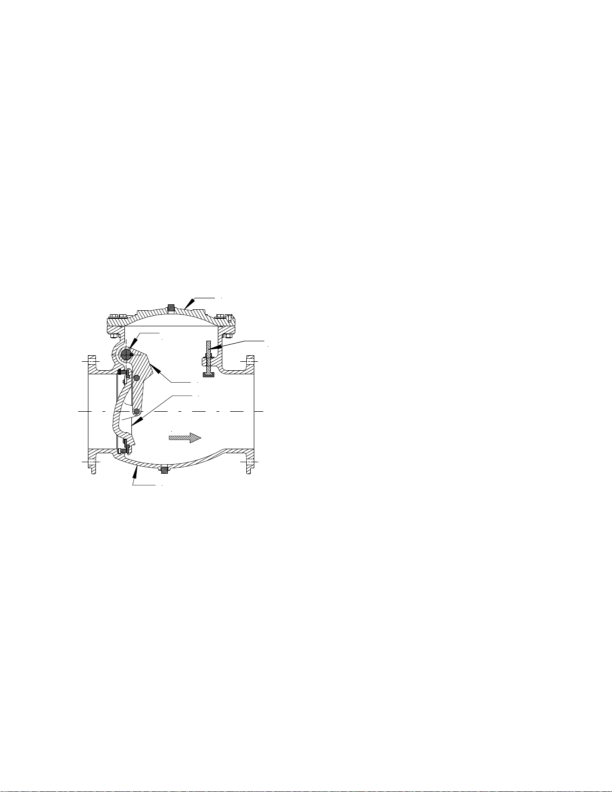
COVER
HINGE
PIN
YOKE ARM
DISC
FLOW
BODY
FIGURE 1. SWING CHECK VALVE
The body has two eccentrically located hinge pin
trunnions that contain the hinge bushings and
hinge packing. A continuous stainless steel hinge
pin passes through the bushings and the disc yoke
arm. The disc yoke arm is keyed to the hinge to
lock them together rotationally. The disc is
attached to the disc arm with two stainless steel
pins, making the disc and disc yoke arm a solid
assembly. The Buna-N disc seal ring fits into a
recessed register in the face of the disc and is
captured and retained by a large circular retaining
ring or segments and stainless steel screws. The
Buna-N disc seal has O-ring type sealing beads
that provide low pressure sealing when it contacts
the stainless steel seat ring, located in a machined
register in the body. The seat ring has a groove on
its outside diameter, which accepts an O-ring, that
STOP
BOLT
creates a seal between the interface of the inside
diameter of the body register and the outside
diameter of the seat ring.
The stainless steel body seat ring is threaded into
the body in 2” through 12” sizes and retained to
the body with stainless steel set screws that
engage a groove within the body seat register in
larger sizes. The exterior portion of the body has
machined mounting pads on each side of the
valve. The lower portion of the air cushion
assembly is mounted to these pads. An additional
pad accepts a spring assembly.
The counterweight arm assembly is keyed to the
extended portion of the pivot shaft. The
counterweight arm assembly has additional
keyways to allow for multiple mounting positions
such as horizontal or about 30° below when
closed. The counterweights are located on the
counterweight arm and are secured to the lever
with a bolt.
The body and the top cover are provided with
plugged ports. The body port serves as a drain
port and the top cover's port serves as a
connection point for an automatic air release valve
or as a vent port. A drain valve may also be
connected to the body port.
DESCRIPTION OF OPERATION
The valve is designed to prevent reverse flow
automatically. During system flow conditions, the
movement of the fluid forces the disc to the open
position allowing 100% un-restricted flow area
through the valve. Under reverse flow conditions,
the disc automatically returns to the closed
position to prevent reverse flow.
Upon pump start-up the forward flow of the water
will start to rotate the disc about the hinge until the
disc contacts the stop bolt in the valve body. The
disc rotates through a 60 to 70 degree arc from
the closed to the fully open position. On pump
shut down the forward velocity of the water will
start to diminish, as the forward velocity of the
water is further reduced, the disc will start its travel
to the closed position. When the forward velocity
of the water reaches zero, the disc has moved to
the closed position and the reversal of the flow is
checked. Under these ideal hydraulic conditions
the valve should close without water hammer.
However, ideal hydraulic conditions are not always
predictable and the potential for water hammer
exists. If the reversal of flow happens before the
Page 3 of 13

VAL-MATIC'S SWING CHECK VALVE
OPERATION, MAINTENANCE AND INSTALLATION
disc has a chance to react to the diminishing
forward velocity of the water, the disc will be
driven to the closed position by the rapid flow
reversal. Depending on how fast the reversal of
flow takes place, a water hammer of different
magnitudes will develop.
The valve is available with an adjustable lever and
weight, an optional and adjustable lever and
spring assembly and a side mounted air cushion.
These assemblies and adjustments may be used
to vary the valve’s closing operation in order to
reduce the magnitude of the closing water
hammer.
The side mounted air cushion was designed to
solve minor water hammer problems. It should be
stated, that because the control media is only a
small volume of air at atmospheric pressure, that
is compressed to a maximum of 200 PSI and then
vented to the atmosphere thru a small flow control
valve, it should not be considered as a total
solution for severe water hammer problems.
INSTALLATION
The swing check valve with spring, weight and
lever, or weight, lever and
cushion can only be used for horizontal flow or
vertical flow-up applications. The valve must be in
a laminar flow region of the piping system. Avoid
locating the valve immediately downstream of a
pipe elbow or in a cavitation zone because the
turbulence in these regions will cause excessive
disc motion and will result in premature wear.
For horizontal flow applications the valve must be
installed with both of the pivot trunnions located
above the horizontal center-line of the valve and
the common center-line of the hinge trunnions
must be level to the horizontal plane of the valve.
For vertical flow up applications the counterweight
arm should be in the horizontal or about 30° below
horizontal position when the valve is
position. The counterweight arm has multiple
keyways to allow for mounting in several
orientations.
Before installing the valve in the space provided,
check to make sure that the pump discharge
piping is free of foreign objects such as lumber,
tools, rocks, etc., which can damage the swing
check valve when it is placed in service.
side mounted air
in the closed
When lifting the valve for installation, make sure
that lifting chains or straps are not attached to or
allowed to come in contact with the hinge pin,
counterweight arm or the side mounted air cushion
assembly. Also do not allow the weight of the
valve to rest on the hinge pin, counterweight arm
or the side mounted air cushion assembly.
Each valve is provided with a flow arrow integrally
cast on the valve cover. The flow arrow must
point in the direction the water will flow, when the
system is operating.
AWWA C508 swing check valves are furnished
with flat faced flanges and should only be mated to
a flat faced companion flange. A full faced or ring
gasket, that has been lubricated with a gasket joint
compound, must be installed between the valve's
flange and the companion flange to effect a seal.
Flange bolting shall be in accordance with ANSI
B16.1 Section 5.2 for cast iron bodies and ANSI
B16.42 for ductile iron bodies. Note: Val-Matic
does not recommend the use of high strength
flange bolting with these valves.
Before installing the flange bolting, the valve and
the adjacent piping must be supported and aligned
to prevent cantilevered stress being transferred to
the valve's flanges when installing the flange bolts
or studs.
Apply a thread lubricant to the flange bolt threads
and install the flange bolts and nuts around the
flange. Once all the flange bolts or studs are
inserted around the flange bolt circle, tighten them
hand tight.
Recommended flange bolt lubricated target torque
values for use with resilient gaskets (75
durometer) are given in Table 1. If leakage
occurs, allow gaskets to absorb system fluid and
check torque and leakage after 24 hours. Do not
exceed the bolt rating, the maximum torque of
Table 1, compress to more than the gasket
manufacturer’s thickness recommendation or
extrude gasket.
Page 4 of 13

VAL-MATIC'S SWING CHECK VALVE
OPERATION, MAINTENANCE AND INSTALLATION
TABLE 2.
FLANGE BOLT TARGET TORQUE
Valve Bolt Recommended Maximum
Size Dia. Torque Torque
(in) (in) (ft-lbs) (ft-lbs)
2” to 4” 5/8 25 90
6”-8” 3/4 30 150
10”-12” 7/8 45 205
14”-16” 1 80 300
18”-20” 1 1/8 100 425
24”-30” 1 1/4 150 600
36”-42” 1 1/2 300 900
48” 1 1/2 300 1,000
The target torque for flange bolting is based on the
flange construction, system pressure, system
temperature, and the gasket material. The valve
flange construction is per ASME B16.1 Class 125
(cast iron bodies) or ASME B16.42 Class 150
(ductile iron bodies). The gasket material and
design is often the limiting factor for the flange bolt
target torque and should best be obtained from the
gasket manufacturer. Note: Flange joint leakage
can be caused by exceeding the recommended
target torque as well as inadequate or non-uniform
bolt torque.
The flange bolt torque should be applied in several
graduated steps using the cross-over bolt
tightening method to load the bolts evenly to
eliminate concentrated stresses which could
fracture or crack the valve's flange. See ASME
PCC-1-2010 for details of the cross-over bolt
tightening sequence and torque methods. Note
that the target torque values provided in ASME
PCC-1-2010 are based on the ANSI/ASME steel
flange pressure and temperature ratings which
exceed those of AWWA and are, therefore, often
higher than appropriate for AWWA rated iron
valves and flanges.
The use of ring gaskets or excessive bolt
torque may damage valve flanges.
VALVE START-UP PROCEDURE
When the swing check valve with weight arm,
spring, and/or side mounted air cushion is
completely installed, follow the steps outlined
below to place valve into service. A combination
of the weight, spring and side mounted
CAUTION
adjustments may be necessary depending on the
valve’s optional equipment configuration and the
installed system performance.
Become familiar with the following adjustments
that will affect the closing characteristics of the
swing check valve's disc.
There is a “Start-Up Observation Record” form at
the end of this manual that may be useful during
start-up operations and recording the “Final, As
Left” set-up configuration.
LEVER AND WEIGHT ADJUSTMENTS
Moving the weight in towards the hinge pin centerline will increase the disc's closing time and
moving the weight out away from the pivot shaft
center-line will decrease the disc's closing time.
Note that the position of the weights can also
affect how far the valve's disc opens under low or
moderate flow conditions.
LEVER AND SPRING ADJUSTMENTS
Moving the spring connection in towards the hinge
pin center-line will increase the disc's closing time
and moving the spring connection out away from
the pivot shaft center-line will decrease the disc's
closing time. Note that the position of the spring
connection can also affect how far the valve's disc
opens under low or moderate flow conditions.
Increasing the spring tension will decrease the
disc's closing time and decreasing the spring
tension will increase the disc's closing time.
AIR CUSHION FLOW CONTROL VALVE
ADJUSTMENTS
There are two speed control valves externally
mounted on the air cushion cylinder ports. To
increase the cushioning effect (increase closure
time) the upper (cylinder rod end) speed control
should be full open and the lower (cylinder cap
end) speed control is used to control the
cushioning effect. Turning the lower external
speed control valve's adjustment knob of the side
mounted air cushion clockwise will increase the
cushioning effect and increase the valve's closing
time and turning the lower external speed control
valve's adjustment knob counter-clockwise will
decrease the cushioning effect and decrease the
valve's disc closing time. If the lower speed
control valve is fully opened and a reduction in the
closure time is desired, the upper (cylinder rod
end) speed control valve should be fully closed
while the swing check valve is in the full closed
position. This will add a pressure boost to the
initial portion of the closing stroke.
Page 5 of 13

VAL-MATIC'S SWING CHECK VALVE
OPERATION, MAINTENANCE AND INSTALLATION
INITIAL SETTINGS
1. Before starting pump and placing valve into
service, care must be taken to insure that the
pump's intake structure is free of foreign
objects such as lumber, tools, rocks, etc.,
which can damage the swing check valve.
2. If equipped with a side mounted air cushion,
the upper (cylinder rod end) external speed
control valve of the side mounted air cushion
will be factory set in the full closed position
and the lower (cylinder cap end) external
speed control valve of the side mounted air
cushion will be factory set in a full open
position. These settings provide a pressure
boost to the initial portion of the closing stroke.
3. If equipped with a weight and lever, connect
the weight as far as possible from the centerline of the hinge pin and bolt to hold the weight
secure.
4. If equipped with a spring assembly, connect
the spring as far as possible from the centerline of the hinge pin and the tension of the
spring should be adjusted with the bolt to hold
the spring secure.
CAUTION
These initial settings provide the fastest
check valve closure.
The closure time should be selected,
tested, set, and determined by the user or
his designee who is expert in the installed
piping system as the system’s response to
the valve’s closure can vary greatly and the
system induced transient pressure can
cause severe damage to the valve and
other piping system components.
TROUBLESHOOTING
Several problems and solutions are presented
below to assist you in troubleshooting the valve
assembly in an efficient manner.
Leakage at Hinge Pin: Adjust or replace
packing.
Leakage at Cover or Flanges: Tighten cover or
flange bolts, replace cover seal or flange
gasket.
Valve Leaks When Closed: Inspect disc
rubber seat for damage or debris. Clean or
replace as needed. Inspect body stainless
steel seating surface for damage or debris.
Clean, polish, or replace as needed.
Valve Does Not Open: Check for obstruction
in valve or pipeline; see disassembly
procedure. Operating pressure may be less
than cracking pressure. If less than 0.5 psig,
review application with factory.
DISASSEMBLY
The valve can be disassembled without removing
it from the pipeline. The valve may also be
removed from the pipeline. All work on the valve
should be performed by a skilled mechanic with
proper tools and a power hoist for larger valves.
Disassembly may be required to inspect the disc
for wear or the valve for debris or deposits.
Refer to Figure 2 for parts identification. Always
relieve pressure and drain pipeline before working
on the valve.
WARNING
The pipeline must be relieved of all
pressure and drained before removing the
valve or the valve cover or pressure may be
released causing bodily harm.
SPRING REMOVAL
1. For safety, wrap, restrain and tie the spring
(50) with rags, slings, or rope in case of a
sudden release.
2. Carefully remove nut (57) and spring bolt (52).
Note: The spring bolt (52) may be match
marked to assure re-assembly to the same
tension setting.
3. Remove Spring (50).
4. Remove Lever (51).
5. Remove Key (54).
6. Remove spring bracket (53), bolts (55) and
washers (56).
WEIGHT AND LEVER REMOVAL
1. Support or prepare to lift weight (31).
Carefully remove nut (35), washer (36), and
bolt (34).
2. Remove weight (31). Note: Mark or record
the weight (31) location on the lever arm (30).
3. Remove bolt (33) and lever (30).
4. Remove Key (32).
5. Remove weight and lever and cylinder bracket
(40), bolts (46) and washers (47).
Page 6 of 13

VAL-MATIC'S SWING CHECK VALVE
OPERATION, MAINTENANCE AND INSTALLATION
AIR CUSHION REMOVAL
1. Support or prepare to lift cylinder (42).
Carefully remove clevis pins (43 and 44).
2. Remove cylinder (42).
3. Remove bolt (46) and lever (45).
4. Remove Key (32).
5. Remove weight and lever and cylinder bracket
(40), bolts (46) and washers (47).
VALVE DISASSEMBLY
1. Remove the cover bolts, nuts, and washers
(24, 28, & 29) on the top cover.
2. Pry cover (2) loose and lift off valve body.
Valves 14” and larger have 3 tapped holes in
cover for lifting eyes. See Table 2 for lifting
eye bolt sizes.
3. If desired, remove stop bolt (60), washer (61)
and nut (62). The stop bolt (60) should be
match marked to assure re-installation to the
same extension length.
4. Sling and support yoke arm (4) and disc (3)
slightly off the seat (23)
5. Remove bolts (20), washers (19) and o-ring
(22) from blind hinge cover (18-2).
6. Remove bolts (20) and washers (19) from
through hinge cover (18-1).
7. Remove packing (16) and packing shim (15).
8. Push hinge pin from keyed end out of blind
end side until retaining ring (21) can be
removed. Remove retaining ring (21).
9. Continue to push hinge pin out until blind end
bushing (14) moves out and can be removed.
Remove bushing (14).
10. Push hinge pin back into the blind end until the
bushing (14) on the keyed and of the hinge pin
is moved enough to remove. Remove bushing
(14).
11. Slide the supported yoke arm (4) and disc (3)
back and forth on the hinge pin until the key
(6) can be removed from between the yoke
arm (4) and the body (1). Note: Take care not
to damage the disc seat (8) or the body seat
(11) while moving yoke arm (4) and disc (3).
Remove key (6)
12. Remove hinge pin (5) from keyed end.
13. Lift the supported yoke arm (4) and disc (3)
and place on a clean floor or pallet.
14. If desired, disassemble yoke arm (4), retaining
rings (25), disc pins (24), and disc (3).
15. Remove seat retaining bolts (10), washer (9),
seat retaining segments (7) and rubber seat
(8).
16. Remove body seat (11). In 12” and smaller
valves, the seat (11) is screwed into the body
and must be threaded into place. In 14” and
large the seat (11) is held into the body with
set screws (12). Remove he body seat (11),
set screws (12), and o-ring (23).
17. Clean and inspect parts. Replace worn parts
as necessary and lubricate parts with FDA
grease such as Lubriko #CW-606.
Page 7 of 13

VAL-MATIC'S SWING CHECK VALVE
OPERATION, MAINTENANCE AND INSTALLATION
SWING CHECK VALVE
PARTS CONSTRUCTION
FOR VALVE DIMENSIONS AND WEIGHTS
SEE THE SUBMITTAL DRA W INGS
19 20
21
14
6
14
15
16
17
18-1
5
2
26
7
9 10
4
24
3
11
12
1
18-2
19 20
292827
8
25
23
22
NOTE:
1.) VALVES CONFORM TO AWW A C508,
LATEST E DITION (2" T H RU 24")
2.) SEE TABLE 2 FOR STANDARD
MATERIALS OF CONSTRUCTION OR
SUBMITTAL DRAW ING FOR SPECIAL
CONSTRUCTION
13
FLOW
13
WITH LEVER
& AIR CUSHION
6160
62
WITH LEVER
32
46
33
& WEIGHT
42
54
& SPRING
44
45
30
FLOW
51
55 56
53
FLOW
43
3635
SPEED CONTROL
VALVE
(TYP.)
50
52
57
3134
40
45 46
FIGURE 2. SWING CHECK VALVE PARTS CONSTRUCTION
Page 8 of 13

VAL-MATIC'S SWING CHECK VALVE
OPERATION, MAINTENANCE AND INSTALLATION
TABLE 3. PARTS AND MATERIALS OF CONSTRUCTION
PART NO.
1 Body Ductile Iron (2” To 24”), Cast Iron (30” To 48”)
2 Cover Ductile Iron (2” To 24”), Cast Iron (30” To 48”)
3 Disc Ductile Iron
4 Arm Ductile Iron
5 Hinge Pin Stainless Steel
6 Hinge Key Stainless Steel
7 Seat Retaining Segment Ductile Iron
8
9 Flat Washer Stainless Steel
10 Hex Hd. Cap Screw Stainless Steel
11 Seat Stainless Steel
12 Set Screw Stainless Steel
13 Pipe Plug Steel
14 Bushing Aluminum Bronze
15
16
17 Packing (Pop) Shim Stainless Steel
18-1 Hinge Cover - Thru Ductile Iron
18-2 Hinge Cover - Blind Ductile Iron
19 Flat Washer Plated Steel
20 Hex Hd. Cap Screw Plated Steel
21 Retaining Ring Stainless Steel
22
23
24 Disc Pin Stainless Steel
25 External Retaining Ring Stainless Steel
26
27 Flat Washer Plated Steel
28 Hex Hd. Bolt Plated Steel
29 Hex Nut Plated Steel
30 Weight Lever Ductile Iron
31 Weight Ductile Iron
32 Key Steel
33 Bolt Plated Steel
34 Bolt Plated Steel
35 Nut Plated Steel
36 Washer Plated Steel
40 Cylinder Bracket Steel
42 Cylinder Steel
43 Cylinder Pin Plated Steel
44 Clevis Pin Plated Steel
45 Cylinder Lever Ductile Iron
46 Bolt Plated Steel
47 Washer Plated Steel
50 Spring Plated Alloy Steel
51 Spring Lever Ductile Iron
60 Stop Bolt Stainless Steel With Buna N
61 Flat Washer Stainless Steel
62 Hex Nut Stainless Steel
PART NAME MATERIAL
Rubber Seat Buna-N
V-Packing Shim Nylon
V-Packing Buna-N
O-Ring Buna-N
O-Ring Buna-N
O-Ring Buna-N
= Recommended Spare Part
Page 9 of 13

VAL-MATIC'S SWING CHECK VALVE
OPERATION, MAINTENANCE AND INSTALLATION
RE-ASSEMBLY
All work on the valve should be performed by a
skilled mechanic with proper tools and a power
hoist for larger valves.
VALVE RE-ASSEMBLY
1. Lubricate body seat o-ring (23) and body seat
(11) with an FDA grease such as Lubriko
#CW-606. Install body seat o-ring (23) and
body seat (11). In 12” and smaller valves, the
seat (11) is screwed into the body. In 14” and
large the seat (11) is held into the body with
set screws (12). Remove he body seat (11),
set screws (12), and o-ring (23)
2. Install rubber seat (8), seat retaining segments
(7), washers (9), and seat retaining bolts (10)
onto disc. Torque bolts to values listed in
Table 4 below. Note: Take caution to protect
the rubber seat from damage during the
remainder of the assemble process.
Table 4. Seat Retaining Bolt Torque
Valve Size Bolt Size Torque (ft-lbs)
2” to 4” M5 5
6” to 20” M8 10
24” to 48” M10 20
3. Assemble yoke arm (4), retaining rings (25),
disc pins (24), and disc (3).
4. Sling and support yoke arm (4) and disc (3).
5. Lift and hang the supported yoke arm (4) and
disc (3) and place into body (1) with yoke
hinge boss nestled in the hinge pin recess
area.
6. Install hinge pin (5) and yoke key (6) from
keyed end engaging the key into the keyway
of the yoke (4). Note: The hinge pin may be
installed with the key oriented toward either
side of the valve. The keyed end of hinge pin
(5) must be oriented to the side where the
spring assembly, lever & weight assembly,
and /or air cushion assembly is to be mounted.
7. Install bushings (14) from both ends of hinge
pin (5).
8. Push hinge out the non-keyed end of the
hinge pin until the retaining ring (21) can be
installed and install the retaining ring.
9. Push hinge (5) back into the body until
retaining ring (21) is seating at the back of the
bushing (14). Install bolts, (20) washers (19)
and o-ring (22) with blind hinge cover (18-2).
10. Install packing (16) and packing shim (15).
11. Install bolts (20) and washers (19) with
through hinge cover (18-1).
12. Install stop bolt (60), washer (61) and nut (62).
Set at desired extension length.
13. Lubricate cove o-ring (26) and grove on top of
body (1) with an FDA grease such as Lubriko
#CW-606. Install o-ring (26) on top of body
(1). Place cover (2) on top of body in the
correct orientation with the flow arrow pointing
away from the hinge pin.
14. Install cover bolts (28), washers (27), and nuts
(29). Torque bolts and nuts to the values
listed in Table 5 below in several graduated
steps using the cross-over bolt tightening
method.
Table 5. Cover Bolt Torque
Valve Size Bolt Size Torque (ft-lbs)
2” to 2 ½” M10 50
3” to 4” M12 75
6” to 18” M20 250
20” to 36” M24 500
42” to 48” M30 750
15. Install pipe plugs (13) are not installed into
body (1) and Cover (2) if not already installed.
Note: Vent, drain and/or air release valves
may also be installed into these ports in lieu of
the pipe plugs furnished.
16. If desire, pressure test the body for packing
and cover leaks. Adjust or replace as
necessary.
17. Install spring assembly, lever and weight
assembly and/or air cushion assembly.
SPRING RE-ASSEMBLY
1. For safety, wrap, restrain and tie the spring
(50) with rags, slings, or rope in case of a
sudden release.
2. Install spring bracket (53), bolts (55) and
washers (56).
3. Install Key (54).
4. Install Lever (51).
5. Install Spring (50).
6. Carefully Install nut (57) and spring bolt
(52). Set nut (57) and spring bolt (52)to the
desired tension setting
WEIGHT AND LEVER RE-ASSEMBLY
1. Install weight and lever and cylinder bracket
(40), bolts (46) and washers (47).
2. Install key (32).
3. Install lever (30). Note: Lever has multiple
Page 10 of 13

VAL-MATIC'S SWING CHECK VALVE
OPERATION, MAINTENANCE AND INSTALLATION
keyways for installing at various
orientations.
4. Install weight (31) at the desired location.
5. Install nut (35), washer (36), and bolt (34)
on lever (30).
AIR CUSHION RE-ASSEMBLY
1. Install weight and lever and cylinder bracket
(40), bolts (46) and washers (47).
2. Install Key (32).
3. Install bolt (46) and lever (45).
4. Install cylinder (42) with clevis pins (43 and
44).
PARTS AND SERVICE
Parts and service are available from your local
representative or the factory. Make note of the
valve Model No. and Working Pressure located on
the valve nameplate and contact:
Val-Matic Valve and Mfg. Corp.
905 Riverside Drive
Elmhurst, IL 60126
Phone: (630) 941-7600
Fax: (630) 941-8042
A sales representative will quote prices for parts or
arrange for service as needed.
Page 11 of 13

VAL-MATIC'S SWING CHECK VALVE
OPERATION, MAINTENANCE AND INSTALLATION
START-UP OBSERVATION RECORD
Site or Facility
Valve Description
[Size, Location, Tag, &/or EIN]
Equipped Configuration
Weight
Position
On
Lever
RUN
No.
C/L
Hinge
To
C/L
Weight
Bolt
Hole
Inches
Control
Position
Flow
Turns
Open
Lever & Weight Side Mounted Air Cushion
Lever & Spring Other
Spring
Position
On
Lever
C/L
Hinge
To
C/L
Spring
Bolt
Hole
Inches
Extension
Spring
Adjuster
Bolt
Inches
Below
Bracket
Closed
Lever
Arm
Angle
Degrees
From
Level
Open
Arm
Angle
Degrees
From
Level
Results,
Notes
& Comments
1
2
3
4
5
FINAL
AS
LEFT
Data Recorded By: Date:
Page 12 of 13

A
c
h
r
e
a
u
o
N
A
A
N
d
E
n
e
v
.
c
e
h
t
T
R
A
E
M
N
c
u
e
r
o
O
U
Y
p
E
P
T
w
e
e
c
c
b
I
N
C
A
R
e
v
3
A
n
(
a
f
d
s
c
o
M
N
P
E
c
V
S
V
6
h
)
s
a
n
A
O
o
T
m
x
o
m
,
f
p
k
r
O
f
N
0
a
o
c
r
g
o
O
N
R
ll produ
date of s
If the pu
alleged d
transport
at his dis
purchase
manufact
product, i
descripti
WARRA
FITNESS
FFIRM
SHALL C
THE MA
househol
OP
ts are warra
ipment, subj
chaser belie
fect and req
tion prepaid
retion, eith
price. Ot
rer shall no
ts use, instal
n of produc
TIES, WRI
FOR A PA
TION OF F
REATE ANY
UFACTUR
purposes.
VAL-
RATIO
ted to be fre
ct to the limi
es a produ
uest permiss
If the prod
r repair or r
er than to
t be liable f
lation or repl
use, samp
TEN OR
TICULAR P
CT, PROMI
WARRANT
R. These
ATIC'S
, MAINT
LIMI
e of defects i
tations belo
t is defectiv
ion to return
ct is accept
place the pr
epair, repla
r any loss,
acement, la
le or model,
RAL, EXPR
RPOSE AN
SE, DESCR
FROM MA
roducts are
SWING
NANCE
ED WARR
n material a
.
, the purcha
the product;
d for return
duct, f.o.b.
e or refun
osts, expen
eling, instru
warnings
ESS OR I
D MERCHA
PTION OF
UFACTUR
not manufa
HECK
AND IN
NTY
d workmans
ser shall: (a
(b) if permis
nd found to
factory, withi
as describ
ses or dam
tions, inform
r lack of a
PLIED, INC
TABILITY,
RODUCT
R, UNLESS
tured, sold
ALVE
TALLA
ip for a peri
Notify the
ion is given,
be defective
n 60 days o
ed above,
ges of any
ation or tech
y of the fo
LUDING TH
RE MADE
F USE OR
SIGNED BY
r intended
ION
d of one ye
anufacturer,
return the pr
the manufa
receipt, or
urchaser a
ind arising
nical data of
egoing. N
E WARRA
R AUTHOR
SAMPLE O
THE PRESI
or personal,
r from the
state the
duct with
turer will,
efund the
rees that
ut of the
any kind,
OTHER
TIES OF
IZED. NO
MODEL
DENT OF
family or
VAL-M
age 13 of 1
905
Phon
www.
ATIC® VAL
iverside D
(630) 941-7
almatic.com
E AND MAN
r. ● El
00 ● Fa
UFACTURI
hurst, IL 6
(630) 941-8
G CORP.
0126
42
 Loading...