


Manual No.
SBCV-OM1-12
Surgebuster
Check Valve
Operation, Maintenance and
Installation Manual
INTRODUCTION 1
RECEIVING AND STORAGE 1
DESCRIPTION OF OPERATION 1
INSTALLATION 2
VALVE CONSTRUCTION 2
MAINTENANCE 2
TROUBLESHOOTING 3
DISASSEMBLY 3
RE-ASSEMBLY 3
BACKFLOW ACTUATOR (OPTIONAL) 4
MECH. INDICATOR (OPTIONAL) 5
LIMIT SWITCH (OPTIONAL) 5
BOTTOM DASHPOT (OPTIONAL) 6
PARTS AND SERVICE 7
WARRANTY 8
VAL-MATIC
905 Riverside Dr. ● Elmhurst, IL 60126
Phone (630) 941-7600 ● Fax (630) 941-8042
www.valmatic.com
®
VALVE AND MANUFACTURING CORP.
VAL-MATIC'S SURGEBUSTER
CHECK VALVE
OPERATION, MAINTENANCE AND INSTALLATION
INTRODUCTION
The Surgebuster
designed to give years of trouble-free operation.
This manual will provide you with the information
needed to properly install and maintain the valve
and to ensure a long service life. The valve is
opened by the fluid flow in one direction and
closes automatically to prevent flow in the reverse
direction.
An optional backflow actuator may be mounted on
the bottom of the valve to allow manual backflow
through the valve in the reverse direction.
Optional Mechanical Indicators and Limit Switches
may be mounted on the valve cover to provide
local and remote position indication.
The valve is of the swing check type utilizing an
angled seat and fully encapsulated, resilient disc.
It is capable of handling a wide range of fluids
including flows containing suspended solids. The
Size, Flow Direction, Maximum Working Pressure,
and Series No. are stamped on the nameplate for
reference.
Do not use valve for line testing at
pressures higher than nameplate rating or
damage to valve may occur.
The "Maximum Working Pressure" is the nonshock pressure rating of the valve at 150
valve is not intended as an isolation valve for line
testing above the valve rating.
Check Valve has been
CAUTION
o
F. The
RECEIVING AND STORAGE
Inspect valves upon receipt for damage in
shipment. Unload all valves carefully to the ground
without dropping. Do not allow lifting slings or
chains to come in contact with the seat area; use
eyebolts or rods through the flange holes on large
valves.
Do not use threaded holes in cover for
lifting the valve. Serious injury may result.
WARNING
Valves should remain crated, clean and dry until
installed to prevent weather related damage. For
long term storage greater than six months, the
rubber surfaces of the disc should be coated with
a thin film of FDA approved grease such as
Lubriko #CW-606. Do not expose disc to sunlight
or ozone for any extended period.
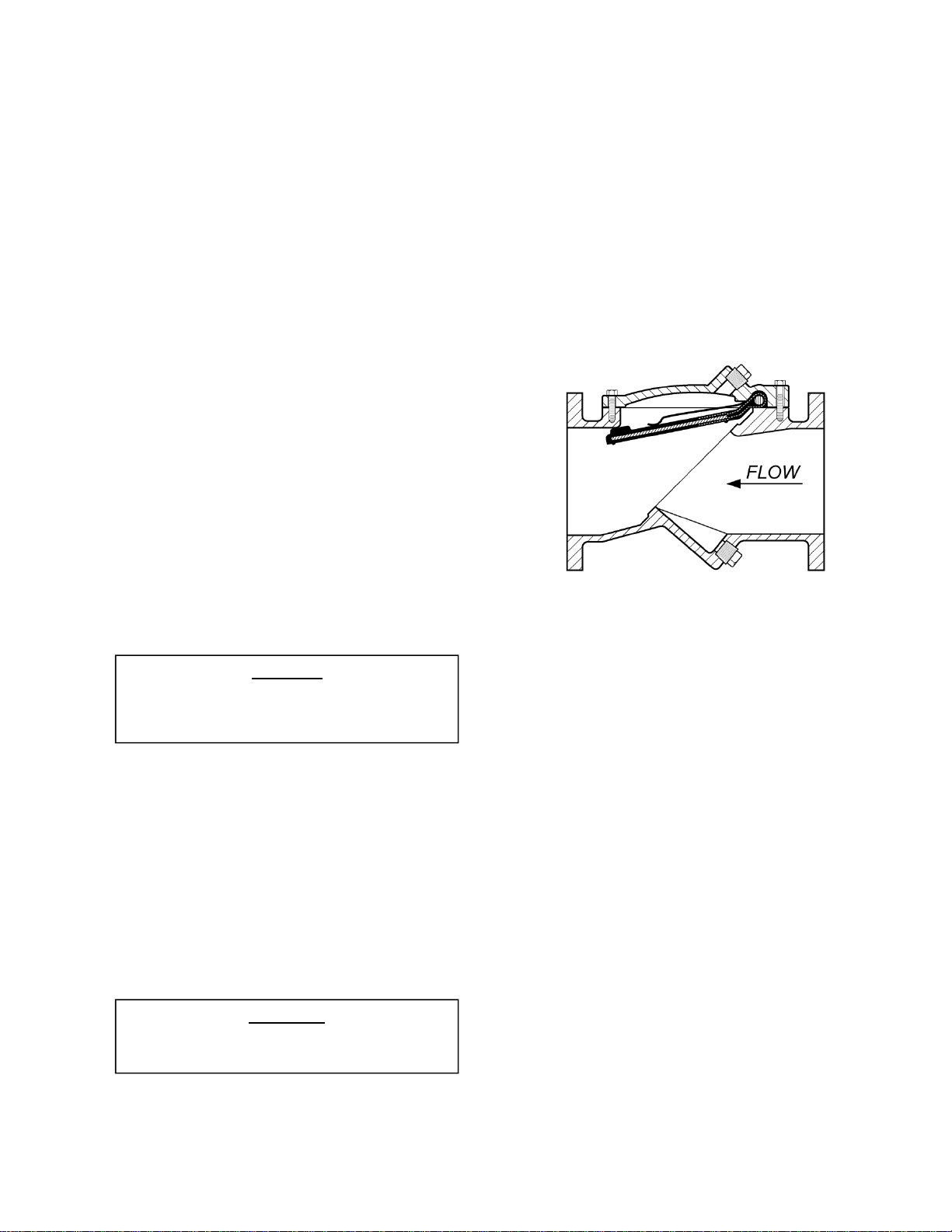
FIGURE 1. SURGEBUSTER
CHECK VALVE
DESCRIPTION OF VALVE OPERATION
The valve is designed to prevent reverse flow
automatically. During system flow conditions, the
movement of the fluid forces the disc to the open
position allowing 100% un-restricted flow area
through the valve. Under reverse flow conditions,
the disc rapidly returns to the closed position to
prevent reverse flow.
Several optional features are a backflow actuator,
mechanical indicator, and limit switch. All of these
options ship loose of the valve and require field
installation.
1
INSTALLATION
Correct installation of the Surgebuster
important for proper operation. It may be installed
in either horizontal or vertical flow-up applications.
However, when horizontal, the valve must be
installed with the nameplate facing up and the
cover level. In all installations, the flow arrow cast
in the valve cover must be pointed in the direction
of flow during normal system operation.
Do not use threaded holes in cover for
lifting the valve. Serious injury may result.
WARNING
FLANGED ENDS: Flanged valves can be mated
with raised or flat-faced pipe flanges equipped with
full-face or ring-type resilient gaskets. The valve
and adjacent piping must be supported and
aligned to prevent cantilevered stress on the
valve. Once the flange bolts or studs are
lubricated and inserted around the flange, tighten
them uniformly hand tight. The tightening of the
bolts should then be done in graduated steps
using the crossover tightening method.
Recommended lubricated torque values for use
with resilient gaskets (75 durometer) are given in
Table 1. If leakage occurs, allow gaskets to absorb
fluid and check torque and leakage after 24 hours.
Do not exceed bolt rating or extrude gasket.
The use of ring gaskets or excessive bolt
torque may damage valve flanges.
CAUTION
Valve Bolt Recom. Max.
Size Dia Torque Torque
(in) (in) (ft-lbs) (ft-lbs)
3 5/8 25 90
4 5/8 25 90
6 3/4 30 150
8 3/4 40 150
10 7/8 45 205
12 7/8 65 205
14 1 80 300
16 1 80 300
18 1 1/8 100 425
20 1 1/8 100 425
24 1 1/4 150 600
30 1 1/4 160 600
36 1 1/2 300 900
42 1 1/2 300 900
Table 1. Flange Bolts Torques
48 1 1/2 300 1,000
is
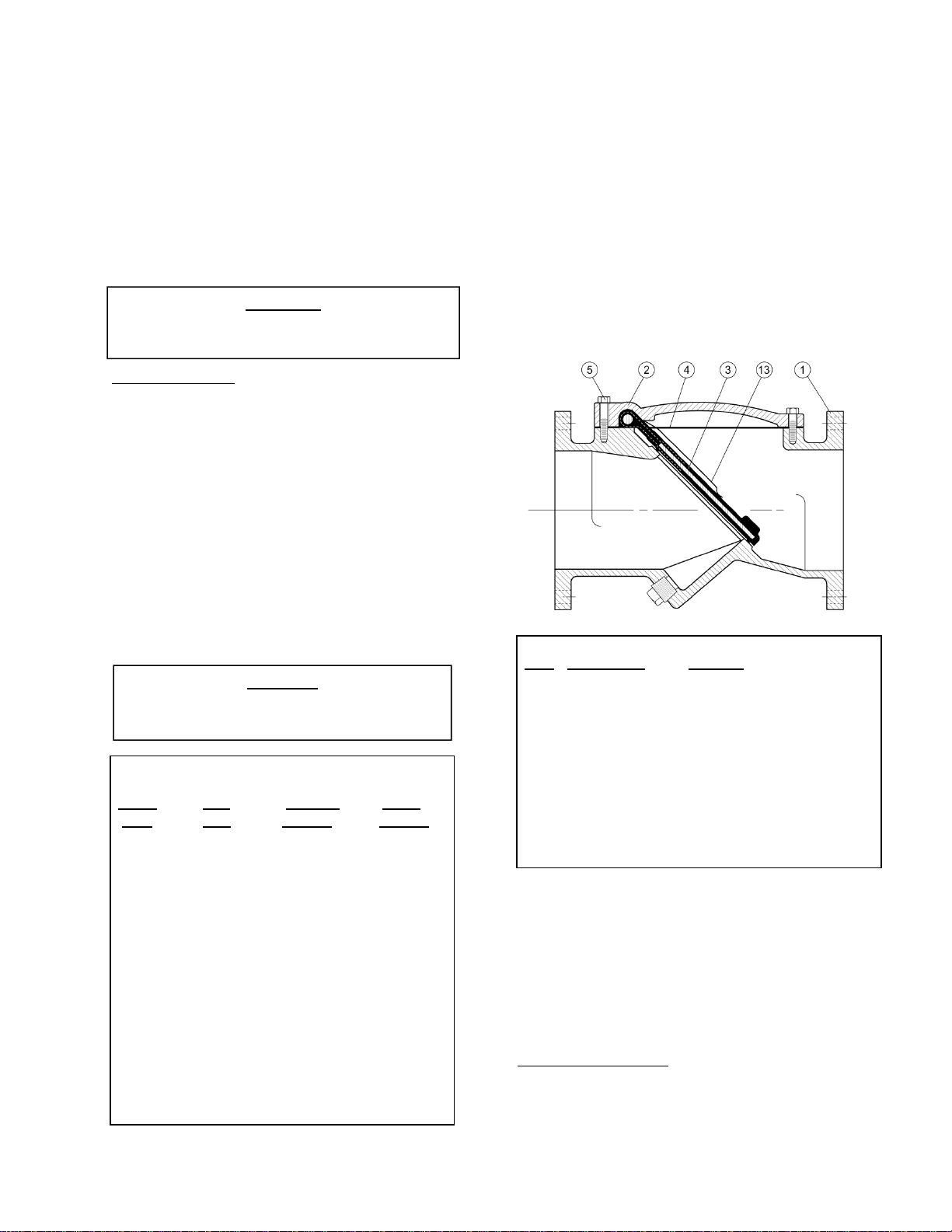
VALVE CONSTRUCTION
The standard Surgebuster
Check Valve is
constructed of rugged cast iron with a rubber
encapsulated disc. See the specific Materials List
submitted for the order if other than standard cast
iron construction. The disc is the only moving part
assuring long life with minimal maintenance. The
general details of construction are illustrated in
Figure 2. The body (1) is flanged for connection to
the pipeline with an open top sealed with a cast
cover (2). The disc (3) and disc accelerator (13)
are retained by the cover.
Item Description Material
1 Body Ductile Iron – 250 psi
Cast Iron – 150 psi
2 Cover Ductile Iron – 250 psi
Cast Iron – 150 psi
3 Disc* Steel With Buna-N Facing
4 Cover Seal* Buna-N or Non-Asbestos
5 Cover Bolt Alloy Steel
13 Accelerator Stainless Steel
*Recommended Spare Part
FIGURE 2. CHECK VALVE CONSTRUCTION
MAINTENANCE
The SurgeBuster
scheduled lubrication or maintenance. For service
or inspection, the valve can be serviced without
removal from the line.
VALVE INSPECTION: If inspection of the valve is
required, follow the Disassembly Instructions given
on page 3.
2
Check Valve requires no

TROUBLESHOOTING
Several problems and solutions are presented
below to assist you in troubleshooting the valve
assembly in an efficient manner.
Leakage at Bottom Actuator: Remove line
pressure and exercise actuator. If leak persists,
replace seals in actuator; see the Backflow
Actuator Seal Replacement Procedure on page
4.
Leakage at Cover or Flanges: Tighten bolts,
replace cover seal.
Valve Leaks when Closed: Inspect disc for
damage and replace. Inspect metal seating
surface and clean if necessary.
Valve Does not Open: Check for obstruction in
valve or pipeline; see Disassembly procedure on
page 4. Operating pressure may be less than
cracking pressure. If less than 0.5 psig, review
application with factory.
Valve Slams Closed: Add additional accelerator.
DISASSEMBLY
The valve can be disassembled without removing
it from the pipeline. Or for convenience, the valve
can be removed from the line. All work on the
valve should be performed by a skilled mechanic
with proper tools and a power hoist for larger
valves. Disassembly may be required to inspect
the disc for wear or the valve for deposits.
The line must be drained before removing
the cover or pressure may be released
causing bodily harm.
1. Relieve pressure and drain the pipeline. Refer
to Figure 2 on page 2. Remove the cover bolts
(5) on the top cover.
2. Pry cover (2) loose and lift off valve body. 14”
and larger valves have tapped holes in cover
for lifting eyes.
3. Remove disc (3) and inspect for cracks, tears
or damage in rubber sealing surface.
4. Clean and inspect parts. Replace worn parts
as necessary and lubricate parts with FDA
grease such as Lubriko #CW-606.
WARNING
RE-ASSEMBLY
All parts must be cleaned. Gasket surfaces should
be cleaned with a stiff wire brush in the direction of
the serrations or machine marks. Worn parts,
gaskets and seals should be replaced during
reassembly.
1. Lay disc (3) over seat with beaded seating
surface directed down.
2. Lay disc accelerator (13) over center of disc
hinge. If two accelerators are provided, stack
them over the center of the disc hinge.
3. Lay cover gasket (4) and cover (2) over bolt
holes and disc hinge. Where o-ring seal is
provided, place o-ring into body groove. O-ring
may be held in place with compatible grease
for re-assembly. Food grade grease should be
used for standard Buna-N o-rings. For EPDM
o-rings, silicone grease should be used.
4. Insert lubricated bolts (5) noting that the bolts in
the hinge area are longer than the other cover
bolts.
5. Cover bolts should be tightened to the following
specifications during assembly.
Table 2. Valve Cover Bolt Torque
Valve Size Torque (ft-lbs)
2”-2.5” 1/2" 75
3” 7/16" 50
4” 1/2" 75
6” 5/8" 150
8” 5/8" 150
10” 7/8" 400
12”-20” 7/8” 400
24” 1” 500
30” 1 1/8” 600
36” 1 1/4” 900
42” 1 1/2" 1,400
48” 1 1/2” 1,400
3

BACKFLOW ACTUATOR FIELD INSTALLATION AND MAINTENANCE (OPTIONAL)
BACKFLOW ACTUATOR OPERATION:
An optional backflow actuator assembly is
available which can be easily installed in the field.
The actuator is not designed to operate at the
valve’s Maximum Working Pressure rating.
Therefore, prior to using the actuator, close the
pump isolation valve and bleed off line pressure.
To operate, turn the handle clockwise. This will
open the valve disc allowing backflow through the
valve. The handle should turn easily. When the
actuator is fully extended into the valve, the disc will
be partially open. Upon completion of the back
flushing operation, turn the handle counterclockwise and the valve will automatically return to
the closed position. Lock the actuator in the closed
position with the jam nut provided. The system is
again ready for normal operation.
Relieve line pressure before using backflow
actuator or damage may occur.
BACKFLOW ACTUATOR FIELD INSTALLATION:
The backflow actuator is supplied as an optional
assembly from the factory, which is shipped loose
with the valve.
Removal of the bottom plug while under
pressure may cause bodily harm.
1. Depressurize and drain the pipeline.
2. Score the coating around and remove the pipe
plug in the bottom boss of the valve.
3. Inspect the backflow rod and place in the nonextended position. (The rod should extend about
1" past the end of the brass bushing.) Apply
Teflon thread sealant to brass threads.
4. Insert the threaded end of the assembly into the
valve boss. Slowly turn the assembly into the
boss taking care not to cross-thread the
bushing. Continue turning the assembly into the
valve for a tight fit.
BACKFLOW ACTUATOR SEAL REPLACEMENT:
There are two parts (8 & 9) on the backflow
actuator that are subject to wear. To replace the
seals, the pipeline must first be depressurized and
drained. Next, remove the backflow assembly from
WARNING
WARNING
the valve by turning the brass bushing (6) counterclockwise. Disassemble the actuator as follows:
1. Remove one of the vinyl caps (12).
2. Remove the T-Handle (10) and jam nut (11)
from the rod (7).
3. Remove the rod (7) from the bushing (6) by
screwing in the rod fully clockwise and pull the
rod through the valve end of the bushing (6).
4. Lubricate new seals with FDA approved grease
such as Lubriko #CW-606 and install in the
bushing end grooves.
5. Clean, lubricate, and reinstall rod in bushing.
6. Re-install jam nut (11) and T-Handle (10).
7. Place vinyl cap (12) on handle (10).
8. Apply Teflon thread sealant to bushing and
carefully thread into valve taking care not to
cross-thread the bushing
FIGURE 3. BACKFLOW ACTUATOR ASSEMBLY
Item Description Material
6 Bushing Lead Free Brass
7 Rod Stainless Steel
8 Rod Wiper* Molythane
9 O-Ring* Buna-N
10 Handle Stainless Steel
11 Jam nut Brass
4
12 Cap* Vinyl
Backflow Actuator Parts List
*Recommended Spare Part

MECHANICAL INDICATOR (OPTIONAL)
The mechanical indicator is an option that fits into
the cover and can easily be installed in the field by
going through the following steps. The mechanical
indicator is used to visually indicate when the valve
is opened or closed.
1. Remove line pressure and drain valve.
Removal of the pipe plug while under
pressure may cause bodily harm.
WARNING
2. Score the coating around and remove the pipe
plug from the cover.
3. Apply pipe joint compound to indicator body (21)
threads.
4. Insert the indicator body (21), without the
indicator plate (27), into the valve cover and
tighten. Make sure that two of the tapped holes
in the indicator body (21) are aligned with the
valve and pipeline. This will ensure proper
orientation of the indicator plate.
5. Remove the two socket head screws (31) from
the indicator body (21).
6. Slide the indicator plate (27) over the indicator
rod (23) and spring (28).
7. Align the indicator plate (27) as shown on the
back of this card and secure with the 5mm
socket head screws (31).
8. Connect the spring (28) to the indicator plate (27)
notch
LIMIT SWITCH (OPTIONAL)
The limit switch is used in conjunction with the
Mechanical Indicator. The standard limit switch is
MICROSWITCH Model Number 914CE20-3. The
limit switch is SCADA (Supervisory Control and
Data Acquisition) compatible for applications
requiring open/close indication.
NEMA Ratings: 1, 2, 4, 6, 6P, 12, 13
UL Ratings: 5 AMPS, 1/10 HP, 125 or 250 VAC,
SPDT
Installation:
1. Attach limit switch assembly to indicator using
the supplied screws (34) and bracket (31).
2. Position the assembly so that the switch trips
when the valve is closed.
3. Connect wiring to either the normally open or
normally closed contact as shown in the
schematic diagram.
FIGURE 4. MECHANICAL INDICATORASSEMBLY
Item Description Material
21 Body Brass
22 Bushing Brass
23 Rod Stainless Steel T316
27 Plate Stainless Steel T316
28 Spring Stainless Steel T302
32 Screws Stainless Steel T316
Mechanical Indicator Parts List
FIGURE 5. LIMIT SWITCH ASSEMBLY

BOTTOM MOUNTED OIL DASHPOT FIELD INSTALLATION AND MAINTENANCE
(OPTIONAL)
DASHPOT FIELD INSTALLATION: The bottom
dashpot is supplied as an optional assembly from
the factory. This unit provides control of the disc’s
final 10% travel to the closed position to reduce
valve slam and water hammer. The 10% travel
time is adjustable between 1 and 5 seconds.
1. Depressurize and drain the valve and pipeline.
Removal of the bottom plug in the valve
while under pressure may cause bodily
2. Score the coating around and remove the pipe
plug in the bottom boss of the valve. Apply
Teflon thread sealant or tape to brass threads
on the dashpot.
3. Insert the threaded end of the assembly into the
valve boss. Slowly turn the assembly into the
boss taking care not to cross-thread the
bushing. Continue turning the assembly into the
valve for a tight fit and so that the tank is upright.
4. Adjust the air pressure in the tank to be a
minimum of 50 psi over the line pressure. Set
the flow control valve in the mid position (i.e. 1
turn open). The dashpot rod should be
extended and hold the disc open about 1 inch.
The water line pressure will close the disc.
FIGURE 6. BOTTOM MOUNTED OIL DASHPOT
WARNING
CHECKING OIL AND GREASE LEVELS:
1. The check valve should be closed.
2. The air in the oil reservoir must be bled from the
reservoir, using the air fill valve mounted on the
reservoir.
3. Remove the pipe plug from the oil reservoir fill
port.
4. Add hydraulic fluid equal to Mobil #DTE 24 until
fluid is up to level indicated on the reservoir.
Replace pipe plug.
5. Recharge the reservoir with air pressure to a
minimum of 50 psi over the water line pressure.
6. The grease level cannot be checked but it is
recommended that the grease fitting be charged
with grease twice a year. Use a cartridge
grease gun and pump grease into the fitting
using two full strokes. An FDA approved grease
such as Lubriko #CW-606 should be used
(Master Lubricants Company, Philadelphia, PA)
DASHPOT SEAL REPLACEMENT: There are
several seals in the unit that may require
replacement.
1. Depressurize and drain the valve and pipeline.
2. Unscrew the dashpot from the valve and remove
the 4 bolts holding the dashpot spacer.
3. Replace the (2) rod wipers and o-ring seal.
4. If the oil cylinder is leaking oil, tighten the tie rod
nuts. The cylinder should be returned to the
factory for rebuilding.
5. Reinstall the unit as listed above for a new unit.

HANDPUMP OPERATION: The Dashpot may be
equipped with a hand pump as shown in Figure 7.
The hand pump can be used to drive the valve
partially open using hydraulic oil pressure.
1. To open the Check Valve, close the round
Release Knob (turn clockwise 3 turns), insert the
pump handle into the pump, and stroke the
pump several times.
2. To close the Check Valve, open the Release
Knob (turn counterclockwise 3 turns) to release
the oil pressure.
Hand pump: Simplex Series P1000.
FIGURE 7. DASHPOT WITH HANDPUMP
PARTS AND SERVICE
Parts and service are available from your local
representative or the factory. Make note of the
valve Model No. and Working Pressure located on
the valve nameplate and contact:
Val-Matic Valve and Mfg. Corp.
905 Riverside Drive
Elmhurst, IL 60126
Phone: (630) 941-7600
Fax: (630) 941-8042
www.valmatic.com
A sales representative will quote prices for parts or
arrange for service as needed.

V
Val-Matic Valve and Manufacturing Corporation warrants the Surgebuster to outperform any manufacturer’s normally equipped
Air Cushion, Weight and Lever Swing Check Valve with respect to surge pressure normally generated by check valve closure
for installations within the manufacturer’s published ratings of the valve with regard to pressure, temperature and installation
orientation. Should the Val-Matic Surgebuster fail to outperform any Air Cushion, Weight and Lever Swing Check Valve during
a period of twelve (12) months from the date of installation or eighteen (18) months from the date of shipment, whichever
comes first, Val-Matic shall pay for the cost of replacement of the Surgebuster with a comparably rated Air Cushion, Weight
and Lever Swing Check valve. This warranty is subject to the following restrictions:
1. This warranty shall not apply when valve performance is or has been affected by misuse, abuse or negligence in either
installation, operation or maintenance.
2. This warranty shall not apply to the cost of maintenance, adjustment, or installation of the Surgebuster.
3. The Surgebuster shall not be operated outside the specifications as published by Val-Matic.
4. Notices of claims against this warranty must be sent via certified mail to Val-Matic within 15 days of the first instance of
an event giving rise to a possible claim against this warranty. Val-Matic shall have the right to test and adjust the
Surgebuster and any replacement valve in the customer’s application with the system operating thru full on/off cycles as
needed.
5. If the customer replaces a Surgebuster valve pursuant to this warranty, the installation and application of the new valve
must be identical to that of the valve being replaced in all respects, including, but not limited to, location and placement of
the Surgebuster valve. Val-Matic shall in no event be liable for costs or expenses in excess of the cost of the
replacement valve.
6. This warranty is limited to pressure surges generated by check valve closure under reverse flow conditions. It does not
apply to pressure surges generated by other system dynamics.
7. If, after the customer replaces the Surgebuster with a normally equipped Air Cushion, Weight and Lever Swing Check
Valve and Val-Matic tests such replacement valve in the customer’s application, such tests shows the Surgebuster valve
producing less surge pressure than the replacement valve, then the customer shall be responsible for the expenses
incurred by Val-Matic. If the tests show the Surgebuster valve, after adjustment produced more surge pressure than the
replacement valve, then Val-Matic shall reimburse customer for the documented cost of replacement of the Surgebuster
valve.
8. Val-Matic’s sole liability and the customer’s sole remedy under this warranty and for any and all other claims arising out
of the purchase and use of the Surgebuster valve shall be limited to replacement of the valve. In no event will Val-Matic
be liable for consequential damages even if Val-Matic has been advised of the possibility of such damages. This
warranty is expressly in lieu of any other expressed or implied warranties, including any implied warranty of
merchantability or fitness for a particular purpose, and any other obligation on the part of
9. If Val-Matic shall, at the request of the customer, render assistance of any kind in operating the valve, or any part of it, or
in remedying any defects at the time, the assistance shall in no case be deemed an acknowledgment on Val-Matic’s part
of a breach by it of this warranty, or excuse for any failure of the customer to fully keep and perform the conditions of this
warranty.
10. This warranty shall be construed according to the laws of the State of Illinois. Any actions brought to enforce this
warranty must be brought in the state or federal courts located in Cook County, Illinois. The prevailing party in any
litigation concerning this warranty shall be entitled to recover its reasonable attorney’s fees and costs from the nonprevailing party.
AL-MATIC SURGEBUSTER LIMITED WARRANTY
Val-Matic.
LIMITED WARRANTY
All products are warranted to be free of defects in material and workmanship for a period of one year from the date
of shipment, subject to the limitations below.
If the purchaser believes a product is defective, the purchaser shall: (a) Notify the manufacturer, state the alleged
defect and request permission to return the product; (b) if permission is given, return the product with
transportation prepaid. If the product is accepted for return and found to be defective, the manufacturer will, at his
discretion, either repair or replace the product, f.o.b. factory, within 60 days of receipt, or refund the purchase
price. Other than to repair, replace or refund as described above, purchaser agrees that manufacturer shall not be
liable for any loss, costs, expenses or damages of any kind arising out of the product, its use, installation or
replacement, labeling, instructions, information or technical data of any kind, description of product use, sample or
model, warnings or lack of any of the foregoing. NO OTHER WARRANTIES, WRITTEN OR ORAL, EXPRESS
OR IMPLIED, INCLUDING THE WARRANTIES OF FITNESS FOR A PARTICULAR PURPOSE AND
MERCHANTABILITY, ARE MADE OR AUTHORIZED. NO AFFIRMATION OF FACT, PROMISE, DESCRIPTION
OF PRODUCT OF USE OR SAMPLE OR MODEL SHALL CREATE ANY WARRANTY FROM MANUFACTURER,
UNLESS SIGNED BY THE PRESIDENT OF THE MANUFACTURER. These products are not manufactured, sold
or intended for personal, family or household purposes.

VAL-MATIC
905 Riverside Dr. ● Elmhurst, IL 60126
Phone (630) 941-7600 ● Fax (630) 941-8042
www.valmatic.com
®
VALVE AND MANUFACTURING CORP.
 Loading...