

Val-Matic Rubber-Seated Ball Valve User Manual

Manual No.
BV-OM1-3
®
Val-Matic
Rubber-Seated Ball Valve
Operation, Maintenance and
Installation Manual
INTRODUCTION ....................................... 2
RECEIVING AND STORAGE .................... 2
DESCRIPTION OF OPERATION .............. 2
VALVE CONSTRUCTION ......................... 3
INSTALLATION REQUIREMENTS ........... 4
MAINTENANCE ......................................... 8
TROUBLESHOOTING ............................. 10
DISASSEMBLY ....................................... 10
REASSEMBLY ........................................ 11
PARTS & SERVICE ................................. 12
WARRANTY ............................................ 12
VALVE AND MANUFACTURING CORP.
905 Riverside Dr. ● Elmhurst, IL 60126
Phone (630) 941-7600 ● Fax (630) 941-8042
www.valmatic.com
y
VAL-MATIC'S 4"-48" SERIES 4000 BALL VALVE
OPERATION, MAINTENANCE AND INSTALLATION
INTRODUCTION
The Series 4000 Ball Valve has been designed to
provide long trouble-free operation. This manual will
provide you with the information to properly install and
maintain the valve to ensure a long service life. The
valve is a resilient seated, quarter-turn valve capable of
handling water and wastewater. The Size, Cold
Working Pressure (CWP), and Model No. are stamped
on the nameplate for reference.
CAUTION: Do not use valve for line test ing at
pressures higher than nameplate
rating or leakage and damage to
valve ma
The "Cold Working Pressure" is the non-shock
pressure rating of the valve at 150
discharge service, the valve is intended for flow toward
the seat end of the valve. The “Seat End” is marked
on the nameplate for single-seated valves. This allows
seat adjustment while the valve is holding system
pressure. Double seated valves can be installed with
flow and pressure in either direction.
RECEIVING AND STORAGE
Inspect valves upon receipt for damage in shipment.
Unload all valves carefully to the ground without
dropping. Do not lift valves with slings or chains
around the actuator or through the seat area. Lift valve
with straps or hooks in the lifting eyes integrally cast on
the body flanges. Extra care must be taken when
handling electric motor and cylinder actuated valves.
Valves should remain crated, clean and dry until
installed to prevent weather related damage. The valve
is shipped slightly open to maintain the resilient seat in
the un-loaded condition.
For long-term storage greater than six months, indoor
storage is recommended. The valve flange covers
must remain in place, the valve must remain slightly
open (3-5 degrees), and the rubber surfaces of the ball
should be coated with a thin film of FDA approved
grease such as Dow Corning # 7. Do not expose the
resilient seat to sunlight or ozone for any extended
period.
occur.
o
F. On pump
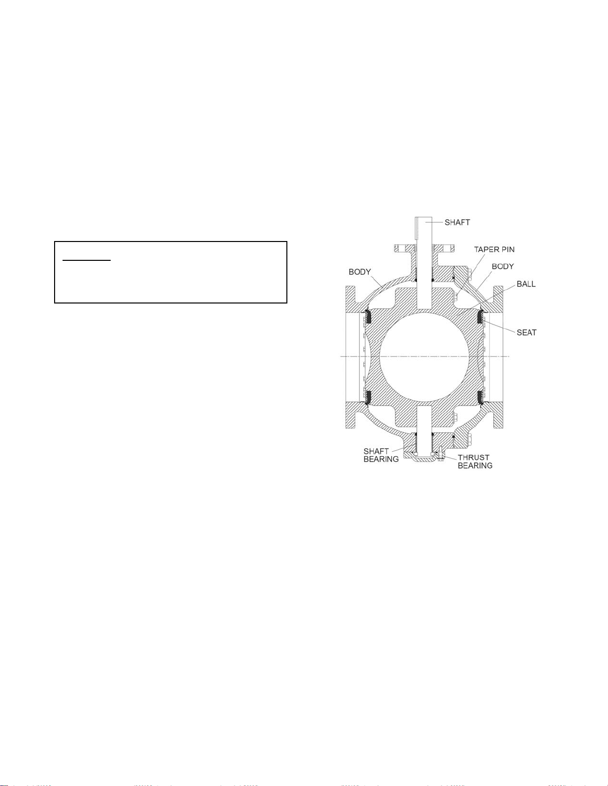
DESCRIPTION OF OPERATION
As shown in Figure 1, the valve consists of a two-piece
body, cast ball, and shafts that rotate in shaft bearings.
The ball is centered in the body with a thrust bearing
assembly. The resilient seats provide drop-tight
shutoff.
FIGURE 1. RESILIENT-SEATED BALL VALVE
The ball is rigidly attached to the shaft with taper pins.
The actuator rotates the valve shaft and ball through
90 degrees of operation. The ball can rotate through
the seat, but is factory set to stop in the center of the
seat to provide tight shut off. Additional torque on the
actuator when against the closed stop of the actuator
will not provide tighter shut off. The valve seat is easily
adjustable or replaceable should wear or damage
occur over time.
The valve is operated with a traveling nut manual
actuator; see Figure 3, which requires multi-turn input
on a handwheel or nut. The valve can also be
automated with power actuators such as an electric
motor or hydraulic cylinder.
2
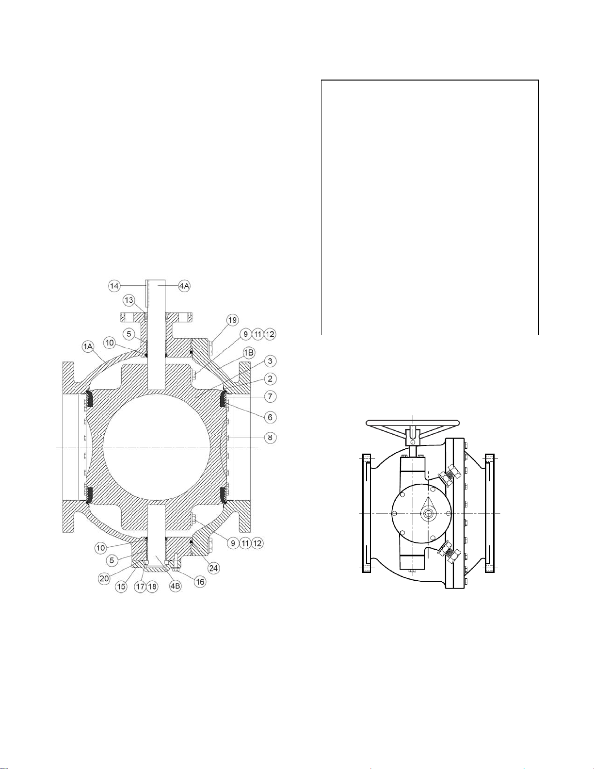
VALVE CONSTRUCTION
The standard Series 4000 Ball Valve is constructed of
rugged cast iron with stainless steel shafts and resilient
seat. See the specific Materials List submitted for the
order if other than standard cast iron construction. The
details of construction are illustrated in Figure 2.
The body (1) is available with Class 150# or Class
300# flanged ends for connection to the pipeline. The
body is equipped with a stainless steel seat (2). The
1/4 turn ball (3) is guided by a stainless steel shaft (4)
which rotates in non-metallic bearings (5) fixed in the
body. Leak-tight closure is made when the resilient
seat (6) located on the ball. If the valve is labeled as a
“Single” seat valve, the seat will be on the right end
and this is the end that is installed toward the pump.
ITEM DESCRIPTION MATERIAL
1 Body Gray or Ductile Iron
2 Body Seat Stainless Steel
3 Ball Gray or Ductile Iron
4 Shaft Stainless Steel
5 Sleeve Bearing* Teflon/Fiberglass
6 Resilient Seat* Resilient
7 Seat Retaining Ring Stainless Steel
8 Ret. Ring Screws* Stainless Steel
9 Taper Pin Stainless Steel
10 Grit Seal * Molythane
11 Taper Pin Bolt Stainless Steel
12 Taper Pin Washer Stainless Steel
13 Packing* Buna-N
14 Key Carbon Steel
15 Thrust Bearing Cap Ductile Iron
16 Cap Screws Carbon Steel, Plated
17 Thrust Brg. Shims Brass
18 Thrust Bearing Bronze
19 Body Bolts Carbon Steel, Plated
20 Cap O-ring Resilient
24 Body O-ring Resilient
*Recommended Spare Part
TABLE 1. STANDARD VALVE PARTS LIST
FIGURE 2. BALL VALVE PARTS LIST
FIGURE 3. VALVE WITH MANUAL ACTUATOR
3
INSTALLATION REQUIREMENTS
Ball valves are a significant component of any water
pumping system or wastewater system. Valve failure
caused by faulty installation, improper operation, or
maintenance in these systems could result in damage,
down time, and costly repairs. In buried or
underground installations, problems or malfunctions
can result in extensive, costly excavation to correct or
eliminate the problem. Many problems with ball valves
can be traced to improper installation, operation, or
maintenance procedures.
OPERATING PARAMETERS: The valve nameplate
lists the maximum pressures and flow rates within
which the valve is intended to operate. If the system
parameters exceed these values, contact the factory
for assistance.
VALVE TYPE: The nameplate will indicate whether
the valve is a “Single” or “Double” seated valve. Flow
direction as discussed below, is important for single
seat valves.
SHAFT ORIENTATION: It is common to install the
valve with the shaft horizontal. This places the
actuator on the side of the pipeline providing good
access to the handwheel, nut, or cylinder actuator
controls. However, the standard valve is designed to
be installed with the shaft in any orientation.
BURIED SERVICE: The valve should be installed with
the shaft horizontal and the actuator nut directed
upwards. The valve box or extension pipe should be
installed so that the actuator nut and extension stem
turn freely.
NOTE: Adjust and test valve prior to backfill.
SEAT ORIENTATION FOR PIPELINE SERVICE: If
the valve is furnished with a single seat, the normal
flow direction is towards the seat end of the valve.
When the flow stops, the return pressure will be held
by the closed ball and the seat bolts (8) can be
adjusted to provide tight shut off should the seat be
worn or damaged. The nameplate is located on the
seat end valve flange. If the valve is furnished with
double seats, flow direction is not important.
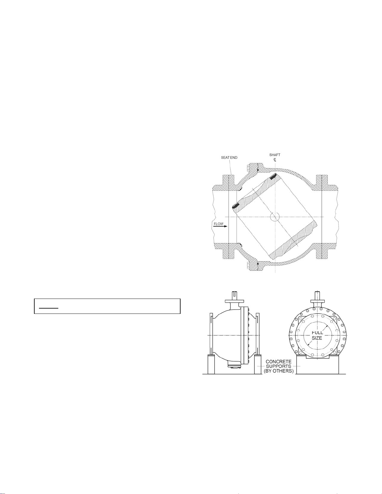
SEAT ORIENTATION FOR PUMP DISCHARGE
SERVICE: On all horizontal pump discharge
applications (Figure 4), the seat end should be towards
the pump to allow seat adjustment with system
pressure against the ball (Figure 4). If the valve is
furnished with double seats, flow direction is not
important.
VALVE SUPPORT: The valve is designed with
integrally cast pads for lifting and supporting the weight
of the valve on a suitable hanger, support, or concrete
pier. The support system should be designed to
support the weight of the valve and not the axial motion
of the piping system, see Figure 5.
FLANGED ENDS: AWWA Class 150 flanged valves
should be mated to ANSI Class 125# flat-faced flanges
equipped with resilient gaskets. When ring gaskets are
used, the bolt material shall be ASTM A307 Grade B or
SAE Grade 2 Carbon Steel. Higher strength bolts may
only be used with full-face gaskets.
FIGURE 4. Flow Direction for Pump Discharge
FIGURE 5. Support Valve Weight
FIELD TESTING
When rubber-seated ball valves are used to isolate
sections of a line for testing, it is important to realize
that these valves are designed or factory adjusted to
hold rated pressure only. If single seated, they hold
pressure in one direction only. Also, test pressures
above valve rated pressure may cause leakage past
the rubber seat and damage to the valve. In order to
4
 Loading...