


Manual No.
CCPV-OM2-3
®
Val-Matic
Cam-Centric® Plug Valve
Operation, Maintenance and
Installation Manual
INTRODUCTION ........................................ 2
RECEIVING AND STORAGE .................... 2
DESCRIPTION OF OPERATION ............... 2
VALVE CONSTRUCTION .......................... 3
INSTALLATION .......................................... 4
MAINTENANCE ......................................... 7
TROUBLESHOOTING ............................... 9
DISASSEMBLY .......................................... 9
REASSEMBLY ......................................... 10
PARTS & SERVICE ................................. 11
WARRANTY ............................................. 11
VALVE AND MANUFACTURING CORP.
905 Riverside Dr. ● Elmhurst, IL 60126
Phone (630) 941-7600 ● Fax (630) 941-8042
www.valmatic.com
VAL-MATIC'S CAM-CENTRIC PLUG VALVE
OPERATION, MAINTENANCE AND INSTALLATION
INTRODUCTION
The Cam-Centric
give years of trouble-free operation. This manual will
provide you with the information to properly install and
maintain the valve to ensure a long service life. The
valve is an eccentric, resilient seated, quarter-turn plug
valve capable of handling many types of fluids
including fluids with suspended solids. The Size,
Cold Working Pressure (CWP), Actuator Rating, and
Model No. are stamped on the nameplate for
reference.
CAUTION: Do not use valve for line testing at
pressures higher than nameplate rating or
leakage and damage to valve may occur.
The "Cold Working Pressure" is the non-shock
pressure rating of the valve at 150
intended as a block valve for line testing above the
valve rating. The “Actuator Rating” is the pressure that
was used to size the actuator for operating conditions
and may be less than the “Cold Working Pressure”.
Because the valve is eccentric, the valve may have a
different actuator rating for reverse and direct pressure.
If the valve is operated at pressures higher than the
actuator ratings, the valve may be difficult to operate or
leak.
RECEIVING AND STORAGE
Inspect valves upon receipt for damage in shipment.
Unload all valves carefully to the ground without
dropping. Do not lift valves with slings or chains
around the actuator or through the seat area.
Valves should remain crated, clean and dry until
installed to prevent weather-related damage. For long
term storage greater than six months, the valve must
remain open and the rubber surfaces of the plug
coated with a thin film of FDA approved grease such
as Dow Corning # 7. Do not expose plug to sunlight or
ozone for any extended period.
DESCRIPTION OF OPERATION
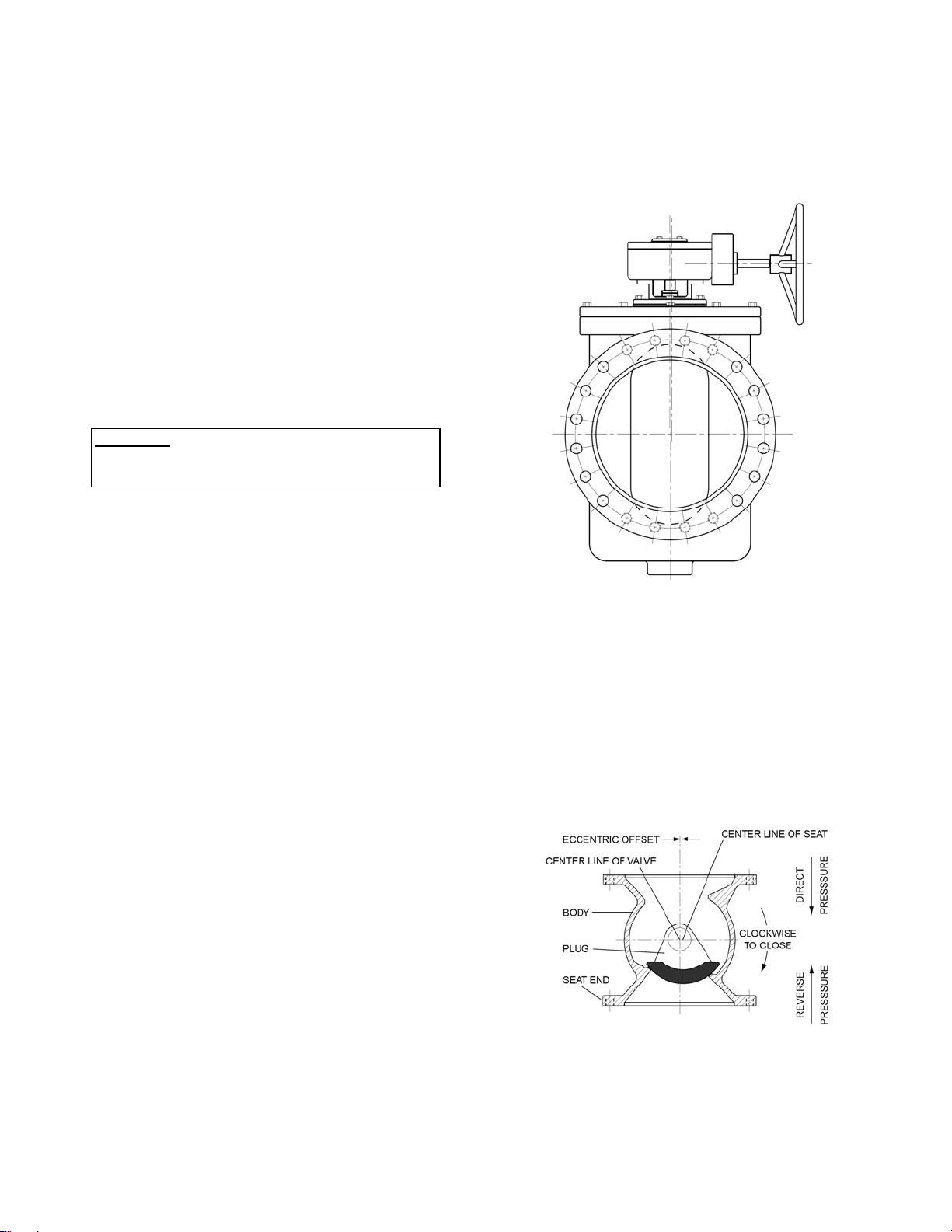
As shown in Figure 2, the valve consists of a body and
quarter-turn plug that is offset from the seat centerline.
Plug Valve has been designed to
o
F. The valve is not
FIGURE 1. PLUG VALVE WITH GEAR ACTUATOR
The eccentric offset causes the plug to lift and rotate
off the seat simultaneously to reduce seat friction and
wear during operation. Direct Pressure pushes the
plug into the seat and Reverse Pressure pushes the
plug away from the seat. The valve can be operated
with a direct nut, lever, or gear actuator. The gear
actuator as shown in Figure 1 requires multi-turn input
on a 2” square nut, handwheel, or chainwheel. The
valve can also be automated with power actuators
such as an electric motor or hydraulic cylinder.
FIGURE 2. PLUG VALVE TERMS
2
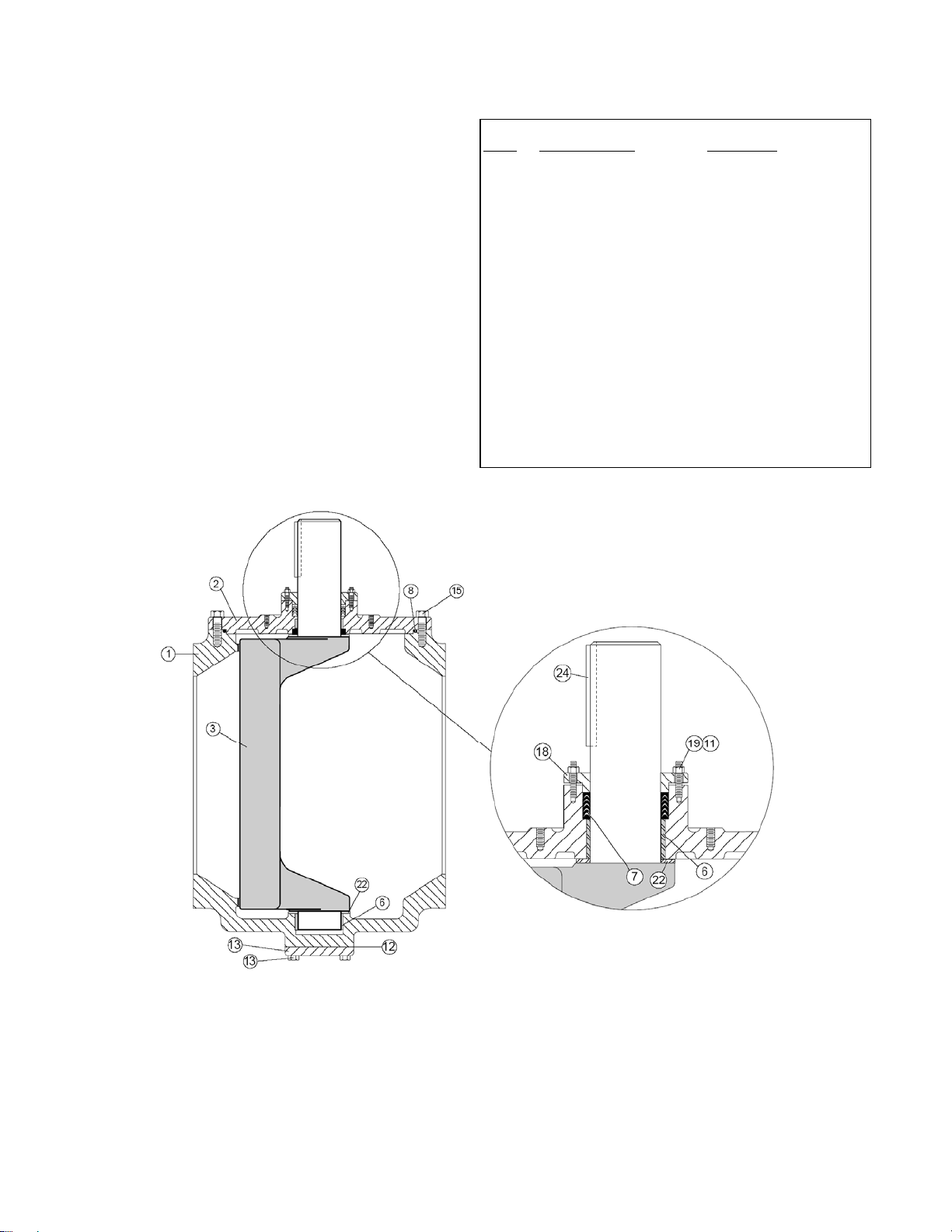
VALVE CONSTRUCTION
The standard Cam-Centric
®
Plug Valve is constructed
of rugged cast iron with a welded nickel seat and
permanently lubricated bearings. See the specific
Materials List submitted for the order if other than
standard cast iron construction. The details of
construction are illustrated in Figure 3.
The body (1) is available with flanged or mechanical
joint ends for connection to the pipeline. The valve is
designed to be serviced in-line by removing the cast
cover (2). The quarter-turn plug (3) is guided by sleeve
bearings (6) located in the cover and lower boss in the
body. Grit-Guard seals (21) are located at the bottom
of the bearings (6) to prevent abrasive material from
wearing the bearing. Leak-tight closure is made when
the rubber-coated plug (3) is rotated into the nickel
seat on the “SEAT END” of the body.
ITEM DESCRIPTION MATERIAL
1 Body Cast Iron with Overlay
2 Cover Cast Iron
3 Plug* Cast Iron with
6 Bearings* 316 Stainless Steel
7 V-Type Packing* Buna-N
8 Cover Seal* Buna-N
15 Cover Bolt Alloy Steel, Gr 5
18 Packing Follower Cast Iron
19 Follower Bolt Alloy Steel, Gr. 5
21 Grit-Guard* Buna-N
22 Thrust Bearing* Teflon
23 Thrust Bearing* 316 Stainless Steel
24 Key Carbon Steel
29 Shims 304 Stainless Steel
*RECOMMENDED SPARE PART
Welded Nickel Seat
Resilient Facing
TABLE 1. STANDARD PLUG VALVE PARTS LIST
FIGURE 3. STANDARD PLUG VALVE CONSTRUCTION
3
INSTALLATION
The installation of the valve is important for its proper
operation. The valve is capable of flow in either
direction but the maximum operating pressure can vary
with the location of the seat end. The words “SEAT
END” are marked on the valve flange. Actuators are
available for pressures up to the full rating in both
direct and reverse pressure orientations. Actuator
ratings will be indicated on the nameplate. Higher
operating pressures may require adjustment of the
closed position stop or a larger actuator; consult the
factory.
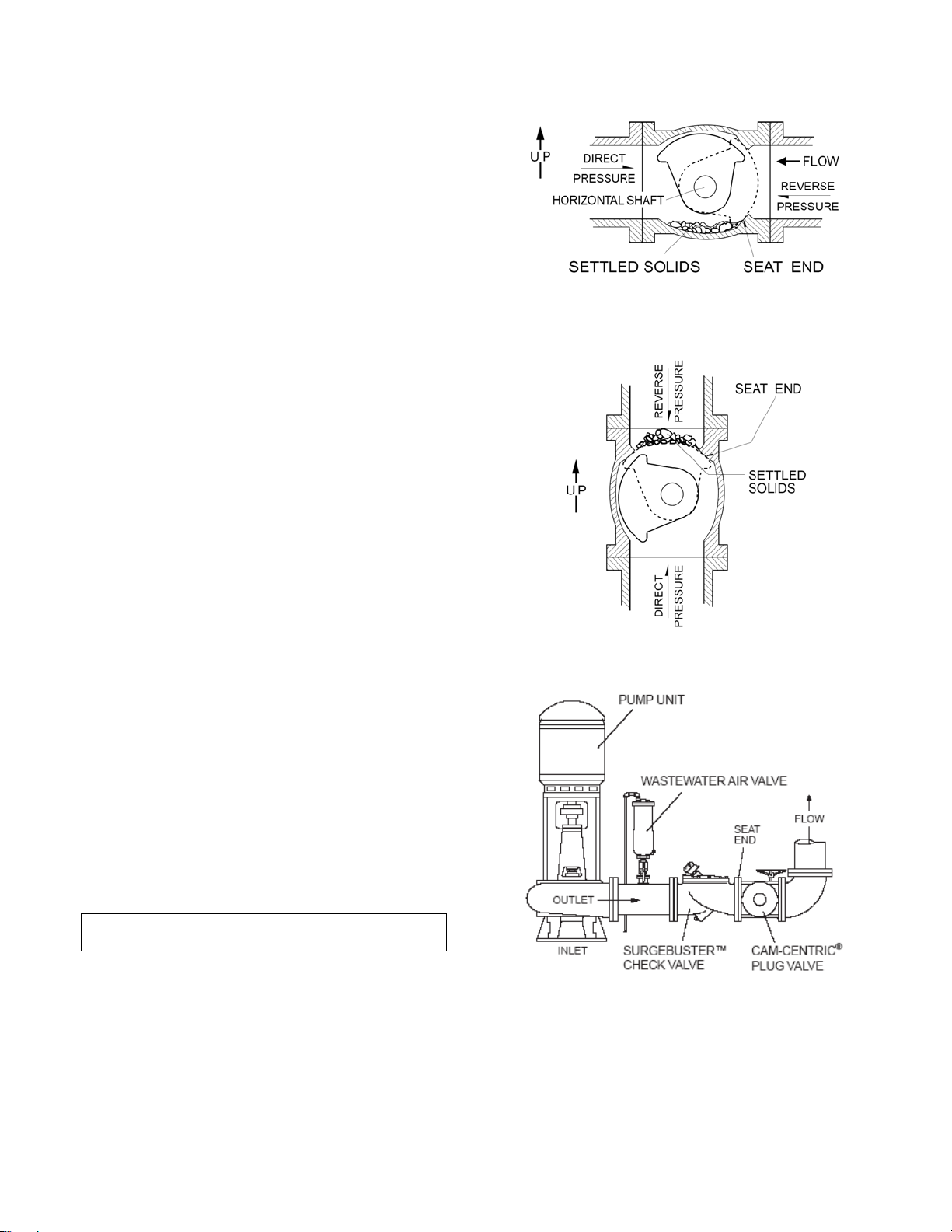
SUSPENDED SOLIDS SERVICE: For fluids
containing suspended solids, special orientations are
needed to prevent debris from collecting in the valve.
For horizontal installations (Figure 4), the valve should
be installed with the flow entering the seat end of the
valve and the shaft in a horizontal position with the
plug up when open. For vertical installations (Figure
5), the valve must be installed with the seat end up
regardless of flow direction.
CLEAN SERVICE: For both horizontal and vertical
installations, install in the direct pressure orientation
(pressure opposite the seat end).
AIR AND GAS SERVICE: Install valve in the direct
pressure orientation (pressure opposite the seat end).
Lubricate plug face with FDA approved silicone grease
such as Dow Corning #7 before installation. Gear
actuators are required for gas service applications.
PUMP DISCHARGE SERVICE: On all horizontal
pump discharge applications (Figure 6), the seat end
should be towards the pump.
BURIED SERVICE: Gear actuators are recommended
for buried valves to hold the valve in position and
provide multi-turn closure to prevent water hammer.
The valve should be installed with the shaft horizontal
and the actuator nut directed upwards. The valve box
or extension pipe should be installed so that the
actuator nut and extension stem turn freely.
NOTE: Adjust and test valve prior to backfill.
FIGURE 4. HORIZONTAL PIPE WITH SOLIDS
FIGURE 5. VERTICAL PIPE WITH SOLIDS
FIGURE 6. PUMP DISCHARGE SERVICE
4

FLANGED ENDS: Flanged valves should be mated
with flat-faced pipe flanges equipped with resilient
gaskets. When ring gaskets are used, the bolt material
should be ASTM A307 Grade B of SAE Grade 2
Carbon Steel. Higher strength bolts may only be used
with full-face gaskets.
The valve and adjacent piping must be supported and
aligned to prevent cantilevered stress on the valve.
Lower valve into line using slings or chains around the
valve body. Lubricate the flange bolts or studs and
insert them around the flange. Lightly turn bolts until
gaps are eliminated.
The torquing of the bolts should then be done in
graduated steps using the cross-over tightening
method. Recommended lubricated torques for use
with resilient gaskets (75 durometer) are given in Table
2. If leakage occurs, allow gaskets to absorb fluid and
check torque and leakage after 24 hours. Do not
exceed bolt rating or crush gasket more than 50
percent of its thickness.
VALVE BOLT RECOM MAX
SIZE DIA TORQUE TORQUE
(in) (in) (ft-lbs) (ft-lbs)
MECHANICAL JOINT ENDS: Clean ends of mating
pipe and valve sockets with soapy water (Figure 7).
3 5/8 25 90
4 5/8 30 90
6 3/4 30 150
8 3/4 40 150
10 7/8 45 205
12 7/8 65 205
14 1 80 300
16 1 90 300
18 1 1/8 100 425
20 1 1/8 120 425
24 1 1/4 150 600
30 1 1/4 175 600
36 1 1/2 175 1000
42 1 1/2 200 1000
48 1 1/2 250 1000
TABLE 2. FLANGE BOLT TORQUES
CAUTION: The use of raised-face flanges
or excessive bolt torque may
damage valve flanges.
Place lubricated gasket and retainer gland over pipe
end prior to installing valve. Install valve socket over
pipe. Press gland and gasket toward valve until gasket
is evenly set into valve socket.
FIGURE 7. MECHANICAL JOINT INSTALLATION
Insert T-bolts in valve flange and hand tighten nuts.
Torque nuts in four graduated steps using the crossover tightening method without exceeding the torque
listed in Table 3. Maintain an equal gap between the
gland and the face of the valve at all points around the
socket.
If a tight connection is not achieved, then the joint
should be disassembled, thoroughly cleaned, and
reassembled. Over-tightening may cause damage to
the valve or gland.
VALVE T-BOLT RECOM MAX
SIZE DIA TORQUE TORQUE
(in) (in) (ft-lbs) (ft-lbs)
3 5/8 45 60
4 3/4 75 90
6 3/4 75 90
8 3/4 75 90
10 3/4 75 90
12 3/4 75 90
14 3/4 75 90
16 3/4 75 90
18 3/4 75 90
20 3/4 75 90
24 3/4 75 90
30 1 100 120
36 1 100 120
42 1-1/4 75 150
48 1-1/4 75 150
TABLE 3. MECHANICAL JOINT NUT TORQUES
5

DIRECT NUT OPERATED VALVES: 8” and smaller
valves may be equipped with a top-mounted nut for
direct quarter-turn operation. The nut is 2” square to fit
most valve wrenches and is mounted directly to the
valve plug. To open the valve, slowly rotate the nut 90
degrees in the counter-clockwise (CCW) direction. The
closed position is adjusted with a set screw and lock
nut, see Figure 8. The open position can be adjusted
by moving the bolt along the curved slot.
FIGURE 8. DIRECT NUT ADJUSTMENTS
DIRECT NUT FRICTION ADJUSTMENT: As shown
in Figure 9, valves with direct nut actuators have a
flanged packing follower (18) above the packing (7)
to hold the valve in the open or closed position. If the
valve is difficult to operate or does not maintain its
set position, adjust the clamp bolt (17) to provide
sufficient friction to hold the valve in position. IF the
valve is equipped with a hand lever, the setting
should allow the valve to be operated with about 80
pounds of force on the end of the pipe handle.
FIGURE 9. FRICTION ADJUSTMENT
LEVER OPERATED VALVES: A wrench head and
lever (Figure 10) are available for use over the 2” nut
for direct quarter-turn operation. Various lever lengths
are available for specific direct and reverse pressure
conditions as shown in Table 4.
VALVE DIRECT PRES. REVERSE PRES.
SIZE 100 psi 175 psi 50 psi 175 psi
2 1/2 22 22 22 22
3 22 22 22 22
4 22 22 22 22
6 44 * 44 *
8 44 * 44 *
*Worm gear recommended due to operating torque
The wrench head is placed over the nut and can be
secured with the set screw provided. To open the
valve, rotate the lever 90 degrees in the CCW
direction. The closed position is adjustable with a set
screw and lock nut mounted below the nut, see Figure
8.
CAUTION: Open and close the valve slowly to
GEAR OPERATED VALVES: 4” and larger plug
valves are available with a multi-turn manual gear
actuator. The gear unit has a self-locking worm gear
which multiplies the turning force on the handwheel or
nut so that the valve can be operated with ease. A
clamp-on chainwheel kit can also be used for
installations high above the floor. An indicator on the
top of the actuator housing indicates the position of the
valve plug. The handwheel or nut must be rotated
through 12-80 turns (depending on model) to open or
close the plug valve. The direction of rotation to open
the valve is indicated on the 2” square actuator nut.
WRENCH LENGTH, (Inches)
TABLE 4. APPLICATION OF LEVERS
FIGURE 10. HANDLEVER
prevent water hammer.
6

GEAR ACTUATOR ADJUSTMENT: The standard
gear actuator is provided with factory-set open and
closed position stops. If the valve does not shut off
tight, the stop bolt can be adjusted allowing the plug to
rotate further into the seat. Loosen the locknut, and
turn the closed stop bolt CCW 1 turn at a time (Figure
11). If the valve continues to leak after all of the
adjustment is taken verify the orientation of the valve
during installation. If a tight shut-off can not be
achieved, a larger gear actuator may be required for
the system operating pressure; consult the factory.
CAUTION: Adjust closed stop bolt for tight
FIGURE 11: GEAR ACTUATOR ADJUSTMENT
shut-off only. Over adjustment
may cause high operating torques
and damage to the plug.
MAINTENANCE
The Cam Centric
lubrication or maintenance other than regular
exercising and occasional inspection of the plug. The
exercising is achieved by fully opening and closing the
valve to verify smooth operation. If operation is
difficult, it may be necessary to flush sediment from the
valve by opening and closing the valve several times
under flowing conditions.
CAUTION: Open and close the valve slowly to
The recommended interval for exercising is every six
months or annually if the valve is regularly operated.
Over the life of the valve, inspection and some regular
adjustments may be needed as given below.
®
Plug Valve requires no scheduled
prevent water hammer.
CLOSED POSITION ADJUSTMENT: The standard
valve is factory-set to seal at the “Actuator Pressure
Ratings” shown on the nameplate for direct and
reverse pressure directions (see Figure 2). Higher
pressure applications may require adjustment of the
closed position stop or a larger actuator; consult the
factory.
If the valve is found to leak in the closed position due
to wear, the plug can be adjusted by loosening the
closed position stop on the actuator and rotating the
plug further into the seat. Because of the eccentric
action of the valve, further rotation will provide
additional interference between the rubber plug surface
and the body seat. Valves that have been in service
for several years may require inspection of the plug for
damage or wear. See the Disassembly Instructions of
this manual.
PACKING ADJUSTMENT: V-type packing is pressure
sensitive and therefore self-adjusting in nature. Over
tightening will destroy both the pressure sensitive
nature of the packing as well as its sealing capabilities.
The packing configuration used in Cam-Centric Plug
Valves follows the guidelines and recommendations of
V-packing manufacturers.
Additional adjustment can be achieved by removing
one or more shims found under the packing follower
(18). If a leak develops, remove one shim (29) from
the underside of the follower (18). An equal number of
shims must be removed from both the left and right
hand sides. Re-tighten the follower bolts (19) and
check for leakage. If the leakage continues, remove
additional shims or replace the packing.
FIGURE 12. PACKING ASSEMBLY
7

PACKING REPLACEMENT: To replace the packing
(7), it is recommended that the line be drained and the
actuator removed. The valve can remain in the line. Te
replace the packing, first open the valve and drain the
line. Close the valve to hold it in position. For power
actuators, turn off and lock out electrical and hydraulic
supplies before proceeding.
CAUTION: Drain line and close valve before
removing actuator or valve may
rotate suddenly. Take precautions
against exposure to toxic or
hazardous fluids in the line.
Remove the small round cover on actuator to expose
shaft and key. Remove actuator mounting bolts and lift
actuator from valve taking care not to lose square key.
See Figure 12 and remove gland bolts (19) and lift
follower (18) from the valve shaft. Remove old packing
(7) with packing hook. Lubricate new packing with
FDA grease and set in place one ring at a time taking
care not to bend over the lips of the packing rings.
Reinstall follower with 2 shims (29) per bolt (3 shims
for 12” and larger valves). With valve in the closed
position, place the actuator over valve and reinsert key
(24). Finally, reinstall cover on actuator indicating
“Closed”.
CAUTION: If packing assembly contains
clamp style follower as shown in
Figure 8, do not lubricate shaft or
sleeve.
PACKING REPLACEMENT WITH ACTUATOR: The
above procedure with removal of the actuator will result
in the most reliable shaft seal. But if the actuator can
not be removed, the following alternate procedure can
be followed. To prevent the possibility of leakage
during this procedure, open valve and drain the line.
CAUTION: Take precautions against
exposure to toxic or hazardous
fluids in the line.
Referring to Figure 12, remove follower bolts (19) and
side follower (18) up to actuator. Remove packing
adapters and rings (7) with packing hook. Cut rings
with knife to remove. New packing rings should be cut
at a 45 degree slope to allow insertion around the shaft
and provide some overlap. Install rings one at a time
with the tips down toward the valve. Stagger all joints
180 degrees around the shaft. Pull down follower (18)
and reinsert bolts (19) with 2 shims (29) under follower
(18). V-packing is pressure assisted and only requires
light compression.
GEAR ACTUATOR MAINTENANCE: A typical gear
actuator is shown in Figure 13 and consists of a worm
(3) mounted on an input shaft (9). The worm engages
a worm wheel (2). When the worm is turned, it drives
the wheel through 90 of rotation. The rotation of the
valve plug is displayed by the top indicator (5). The
open and closed positions of the segment gear are
controlled by an end position stop bolts (20). The
stops can be adjusted by loosening the lock nut (21)
and rotating the bolts. The gears are lubricated with
EP2 grease in a cast iron housing (1). Other parts are
listed in Table 5.
The gear box is factory lubricated and sealed. No
regular maintenance is required. If difficult operation is
observed, the cover (4) can be removed and the unit
inspected for wear. All moving parts should be coated
with grease. The grease should have an even and
smooth consistency. If needed, coat all moving parts
with an lithium-based EP-2 grease such as Shell
Alvania #2 or equal. Buried units should be packed
90% with grease.
FIGURE 13. GEAR ACTUATOR CONSTRUCTION
8

ITEM DESCRIPTION MATERIAL
1 Housing Cast Iron
2 Wormwheel Ductile Iron
3 Worm Steel
4 Cover Cast Iron
5 Indicator Cast Iron
6 O-Ring Buna-N
7 Roller Bearing Steel
8 Shaft Bearing Bronze
9 Shaft Steel
10 Gasket Fiber
11 Handwheel Steel or Iron
12 Operating Nut Iron
13 Chainwheel Iron
14 Cover Bolt Steel
15 Indicator Bolt Steel
16 Pipe Plug Steel
17 Pin Steel
18 Spirol Pin Steel
19 Spring Pin Steel
20 Screw Steel
21 Jam Nut Steel
22 Plug Steel
23 U-Cup Seal Buna-N
TABLE 5. GEAR ACTUATOR PARTS LIST
TROUBLESHOOTING
Several problems and solutions are presented below to
assist you in troubleshooting the valve assembly in an
efficient manner.
• Leakage at Valve Shaft: Adjust or replace packing.
• Leakage at Flanges: Tighten flange bolts, replace
gasket.
• Valve Leaks when Closed: Pressure should be in the
direction of pushing the plug into the seat. Adjust
plug position by rotating the handwheel. Inspect plug
for damage and replace.
• Hard to Open: Flush debris from valve. Check
interior of valve for grit buildup or debris. On buried
valves, check alignment of operating stem.
• Leaking Oil: Tighten actuator cover bolts. If leak
persists, remove actuator cover, inspect grease, and
replace actuator gasket.
• Noisy Operation: Flow noise is normal. Loud flow
noise similar to hammering may be cavitation from
dropping high pressures across valve; review
application of valve. For gear actuator noise, inspect
grease; add new grease if there are uncoated
moving parts or grease has broken down into oil.
DISASSEMBLY
Disassembly may be required to inspect the plug for
wear or remove debris and deposits from the valve.
Work on the valve should be performed by a skilled
mechanic with proper tools and a power hoist for large
valves. The valve can be disassembled without
removing the valve from the pipeline. Refer to Figure
14 for valve construction and parts.
WARNING: Open valve and drain line before
1. Open valve and drain the pipeline. Close valve
until plug just touches the seat. Remove the small
cover on the actuator to expose the shaft key.
2. Remove the actuator mounting bolts and lift
actuator from valve taking care not to lose key
(24).
3. Remove cover bolts (15). Matchmark cover (2)
and body. Screw eye-bolts into actuator mounting
holes and use hoist to lift cover (2) and plug
assembly from valve. Use caution to prevent plug
from dropping while lifting cover. To remove plug
(3) from valve, use sling around top portion of
plug.
4. Inspection of the bearings (6) is done by
measuring diameter of shaft and inside diameter of
bearing. Check for a normal running clearance of
.005". Bearings are permanently lubricated.
5. Thrust bearing assembly (23) and packing gland
(18) can be removed by removing all of the hex
nuts (12).
removing cover bolts or pressure
may be released causing injury.
Place plug in lowest position
before removing actuator or plug
may rotate suddenly and jam or
damage plug surface.
9

REASSEMBLY
All parts must be cleaned and gasket surfaces should
be cleaned with a stiff wire brush in the direction of the
serrations or machine marks. Worn parts, gaskets and
seals should be replaced during reassembly.
FIGURE 14. PLUG VALVE PARTS
1. Press new bearings (6) into cover and body with
round, flat bar 1/4" below inside surfaces of body
(1) and cover (2).
2. Install cover seal (8) over cover lip.
3. Apply thin film of FDA silicone grease such as
Dow Corning #7 to plug rubber surface. Place
stainless steel thrust bearing (23) over lower end
of plug, Teflon bearing (22) over the upper end.
Install grit seals (21) over the shafts of the plug.
4. Carefully place plug into the body (1) and insert
lower plug shaft into bottom bearing (6). Plug (3)
should be in the open position. Install cover (2)
over plug shaft and into recess in body. Align
match marks between body and cover (2). Torque
cover bolts (15) per Table 6 in 3-4 increments
using the cross-over tightening method.
SIZE TORQUE (FT-LBS)
1/2"-13 45 - 75
5/8"-11 100 - 150
3/4"-10 150 - 250
7/8"-9 200 - 350
1"-8 300 - 500
1 1/8"-7 450 - 700
1 1/4"-7 650 - 1000
1 1/2"-6 750 - 1100
TABLE 6. TIGHTENING TORQUES
5. Lubricate ID and OD of packing set with FDA
grease and install in packing bore one ring at a
time taking care to keep lips pointing down toward
plug. Reinstall follower, gland bolts, and 2 shims
per bolt.
NOTE: If valve has friction assembly with direct
nut actuator, follow Friction Adjustment procedure
on page 6.
6. Insert key (24) into shaft and place actuator over
valve. Reinstall actuator mounting bolts and
torque per Table 6. Install cover on actuator.
7. Apply power to actuator and cycle valve. Apply
pressure to valve and check for cover and shaft
leakage. Tighten bolts as necessary. Adjust
packing if necessary.
8. If valve does not shut off tight, adjust the closed
position stop as described on page 6 under
“Closed Position Adjustment.”

PARTS AND SERVICE
Parts and service are available from your local
representative or the factory. Make note of the valve
Size, Series No, and Serial No. located on the valve
nameplate and contact:
Val-Matic Valve and Mfg. Corp.
905 Riverside Drive
Elmhurst, IL 60126
PH: 630/941-7600
FAX: 630/941-8042
A sales representative will quote prices for parts or
arrange for service as needed.
All products are warranted to be free of defects in material and workmanship for a period of one year from the date of shipment,
subject to the limitations below.
If the purchaser believes a product is defective, the purchaser shall: (a) Notify the manufacturer, state the alleged defect and
request permission to return the product; (b) if permission is given, return the product with transportation prepaid. If the product
is accepted for return and found to be defective, the manufacturer will, at his discretion, either repair or replace the product,
f.o.b. factory, within 60 days of receipt, or refund the purchase price. Other than to repair, replace or refund as described
above, purchaser agrees that manufacturer shall not be liable for any loss, costs, expenses or damages of any kind arising out
of the product, its use, installation or replacement, labeling, instructions, information or technical data of any kind, description of
product use, sample or model, warnings or lack of any of the foregoing. NO OTHER WARRANTIES, WRITTEN OR ORAL,
EXPRESS OR IMPLIED, INCLUDING THE WARRANTIES OF FITNESS FOR A PARTICULAR PURPOSE AND
MERCHANTABILITY, ARE MADE OR AUTHORIZED. NO AFFIRMATION OF FACT, PROMISE, DESCRIPTION OF
PRODUCT OF USE OR SAMPLE OR MODEL SHALL CREATE ANY WARRANTY FROM MANUFACTURER, UNLESS
SIGNED BY THE PRESIDENT OF THE MANUFACTURER. These products are not manufactured, sold or intended for
personal, family or household purposes.
LIMITED WARRANTY
VALVE AND MANUFACTURING CORP.
905 Riverside Dr. ● Elmhurst, IL 60126
Phone (630) 941-7600 ● Fax (630) 941-8042
www.valmatic.com
 Loading...