

Val-Matic 3-24 Butterfly Valve User Manual

Manual No.
BFV-OM1-3
Val-Matic®
3"-24" Butterfly Valve
Operation, Maintenance and
Installation Manual
INTRODUCTION .............................................. 2
RECEIVING AND STORAGE ........................... 2
DESCRIPTION OF OPERATION ..................... 2
VALVE CONSTRUCTION ................................. 4
INSTALLATION ................................................ 5
MAINTENANCE ................................................ 7
TROUBLESHOOTING ...................................... 10
DISASSEMBLY ................................................. 10
REASSEMBLY .................................................. 11
SEAT REPLACEMENT ..................................... 11
PARTS & SERVICE .......................................... 12
WARRANTY ..................................................... 12
VALVE AND MANUFACTURING CORP.
905 Riverside Dr. ● Elmhurst, IL 60126
Phone (630) 941-7600 ● Fax (630) 941-8042
www.valmatic.com
VAL-MATIC'S 3"-24" SERIES 2000 BUTTERFLY VALVE
OPERATION, MAINTENANCE AND INSTALLATION
INTRODUCTION
The Series 2000 Butterfly Valve has been designed
to give years of trouble-free operation. This manual
will provide you with the information to properly
install and maintain the valve to ensure a long
service life. The valve is a resilient seated, quarterturn valve capable of handling air, water, or other
clean fluids. For fluids with suspended solids, a
Model 5800R Eccentric Plug Valve should be used.
The Size, Cold Working Pressure (CWP), and Model
No. are stamped on the nameplate for reference.
The "Cold Working Pressure" is the non-shock
pressure rating of the valve at 150
not intended as a block valve for line testing above
the valve rating. The valve is intended for flow
toward the seat end of the valve. The typical flow
direction and “Seat End” are marked on the
nameplate. This allows seat adjustment while the
valve is holding system pressure.
RECEIVING AND STORAGE
Inspect valves upon receipt for damage in shipment.
Unload all valves carefully to the ground without
dropping. Do not lift valves with slings or chains
around the actuator or through the seat area. Extra
care must be taken when handling electric motor
and cylinder actuated valves.
Valves should remain crated, clean and dry until
installed to prevent weather related damage. For
long term storage greater than six months, indoor
storage is recommended. The valve flange covers
must remain in place, the valve must remain slightly
open (3-5 degrees), and the rubber surfaces of the
disc should be coated with a thin film of FDA
approved grease such as Dow Corning # 7. Do not
expose the resilient seat to sunlight or ozone for any
extended period. Electric actuators must be
powered if stored outdoors or in cool areas so that
the internal heaters will prevent condensation in the
control unit.
o
F. The valve is
DESCRIPTION OF OPERATION
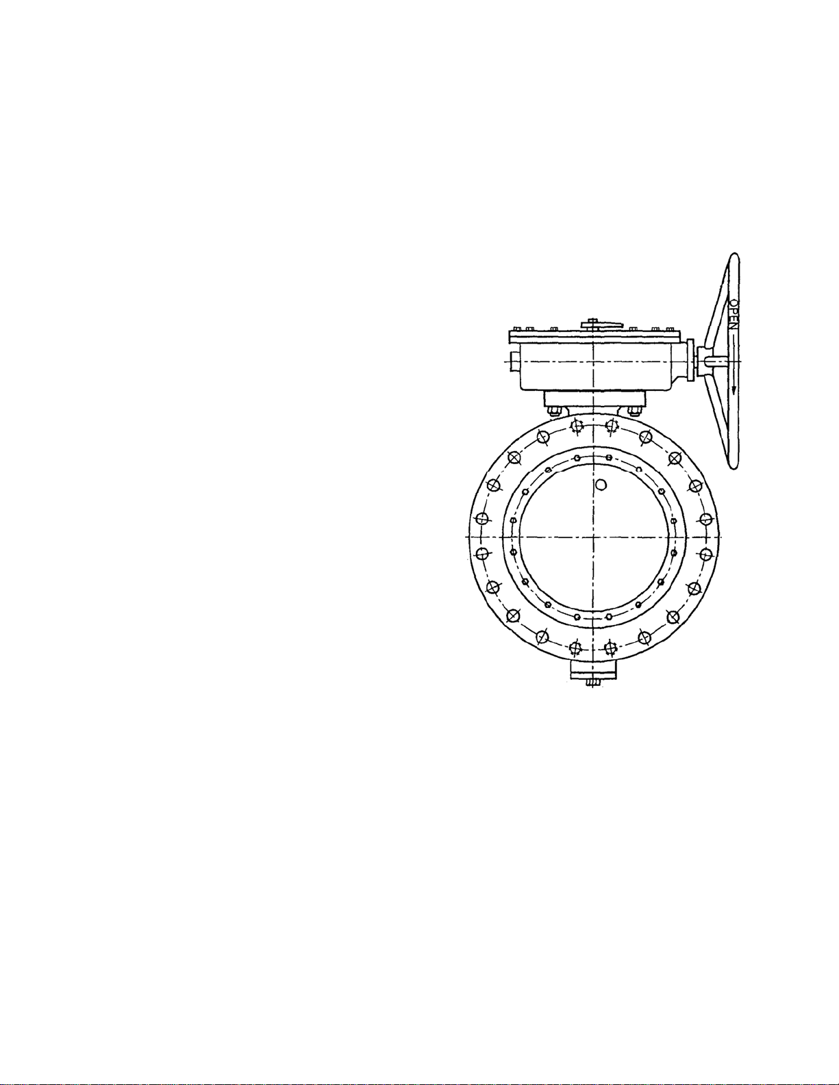
As shown in Figure 1, the valve consists of a body, a
disc, and a shaft that rotates in body bearings. The
resilient seat provides drop-tight shutoff.
FIGURE 1. BUTTERFLY VALVE WITH ACTUATOR
The disc is rigidly attached to the shaft with taper
pins. The actuator rotates the valve shaft and disc
through 90 degrees of operation. The disc can
rotate through the seat, but is factory set to stop in
the center of the seat to provide tight shut off.
Additional torque on the actuator when against the
closed stop of the actuator will not provide tighter
shut off. The valve seat is easily adjustable or
replaceable should wear or damage occur over time.
The valve can be operated with a hand lever or gear
actuator. The gear actuator as shown in Figure 1
requires multi-turn input on a 2" square nut,
handwheel, or chainwheel. The valve can also be
automated with power actuators such as an electric
motor or hydraulic cylinder.
2
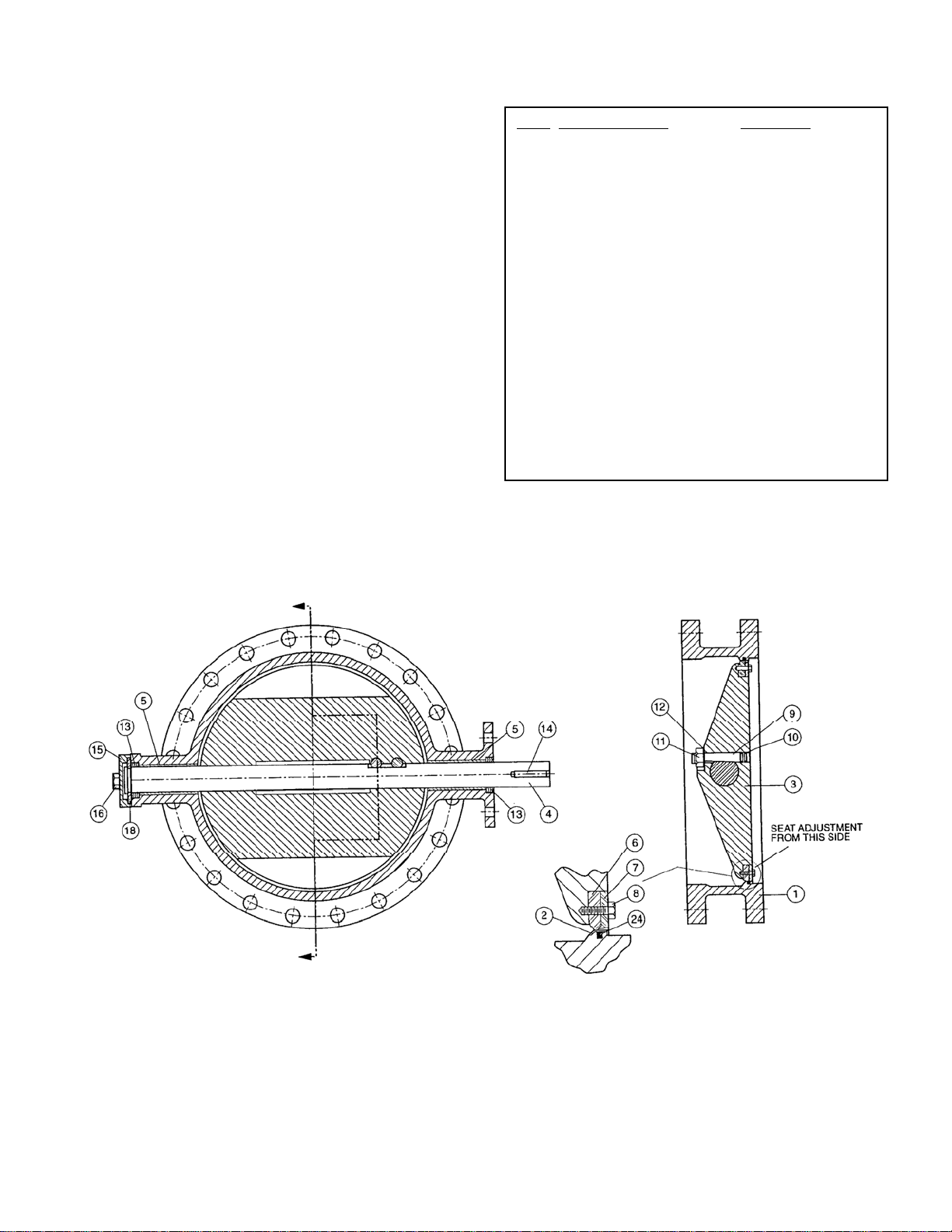
VALVE CONSTRUCTION
The standard Series 2000 Butterfly Valve is
constructed of rugged cast iron with a stainless steel
shaft and resilient disc edge. See the specific
Materials List submitted for the order if other than
standard cast iron construction. The details of
construction are illustrated in Figure 2.
The body (1) is available with flanged or mechanical
joint ends for connection to the pipeline. The body is
equipped with a stainless steel body seat (2). The
1/4 turn disc (3) is guided by a stainless steel shaft
(4) which rotates in non-metallic bearings (5) fixed in
the body. Leak-tight closure is made when the
resilient seat (6) is rotated into the stainless steel
seat on the "SEAT END" of the body.
ITEM DESCRIPTION MATERIAL
1 Body Gray or Ductile Iron
2 Body Seat Stainless Steel
3 Disc Ductile Iron
4 Shaft Stainless Steel
5 Sleeve Bearing* Nylatron
6 Resilient Seat* Buna-N or EPDM
7 Seat Retaining Ring Stainless Steel
8 Ret. Ring Screws* Stainless Steel
9 Taper Pin Stainless Steel
10 Taper Pin O-Ring* Buna-N
11 Taper Pin Nut Stainless Steel
12 Taper Pin Washer Stainless Steel
13 Packing* Buna-N
14 Key Carbon Steel
15 Thrust Bearing Cap Ductile Iron
16 Cap Screws Carbon Steel, Plated
18 Thrust Plate Bronze
24 Body O-Ring EPDM
*Recommended Spare Part
TABLE 1. STANDARD VALVE PARTS LIST
FIGURE 2. STANDARD BUTTERFLY VALVE CONSTRUCTION
3
INSTALLATION
The installation of the valve is important for its
proper operation. Some general recommendations
follow. Some specific piping problems are also
shown in the figures to the right.
WATER SERVICE: The normal flow direction is
towards the seat end of the valve. When the flow
stops, the return pressure will be held by the closed
disc and the seat bolts (8) can be adjusted to
provide tight shut off should the seat be worn or
damaged. The normal flow direction and the words
"SEAT END" are marked on the nameplate which is
located on the seat end valve flange.
AIR AND GAS SERVICE: Install valve with
pressure toward the end opposite the seat end.
Lubricate resilient seat with FDA approved silicone
grease such as Dow Corning #7 before installation.
Gear actuators are recommended for gas service
applications.
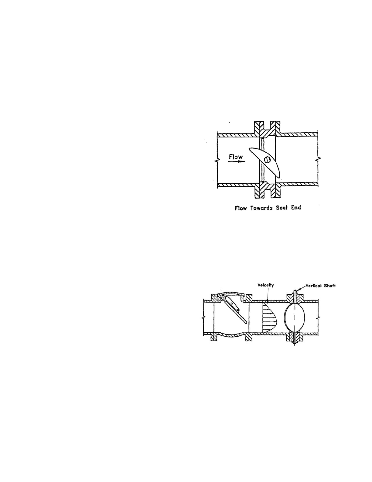
PUMP DISCHARGE SERVICE: On all horizontal
pump discharge applications (Figure 3), the seat
end should be towards the pump to allow seat
adjustment with system pressure against the disc.
The valve shaft should be oriented parallel to the
plane of the pump discharge elbow (i.e. vertical
valve shaft on a vertical discharge elbow). If the
butterfly valve is downstream of a check valve, the
clearance between the two discs must be checked.
The butterfly valve shaft should be oriented as
shown in Figure 4.
BURIED SERVICE: The valve should be installed
with the shaft horizontal and the actuator nut
directed upwards (Figure 4). The valve box or
extension pipe should be installed so that the
actuator nut and extension stem turn freely.
FLANGED ENDS: AWWA Class 150B flanged
valves should be mated to ANSI Class 125# flatfaced flanges equipped with resilient gaskets. When
ring gaskets are used, the bolt material shall be
ASTM A307 Grade B or SAE Grade 2 Carbon Steel.
Higher strength bolts may only be used with full-face
gaskets.
Some of the flange holes are tapped near the shaft
ends of the valve as shown on the Sales Drawing.
Special bolt lengths may be needed. An
engagement of at least one bolt diameter is typically
used for the flange bolts used in the tapped flange
holes.
AWWA Class 250B flanged valves can be mated
with either ANSI Class 125# or ANSI Class 250#
flanges depending on the specified flange drilling.
Class 250B valves can be mated with flat-faced or
raised-face flanges with full face or ring gaskets and
with no bolting restrictions.
FIGURE 3. PUMP DISCHARGE
FIGURE 4. UPSTREAM CHECK VALVE
4
 Loading...