

Val-Matic 2-42 Flanged Vacuum Breaker User Manual

2”- 42” Flanged Vacuum Breaker
Operation, Maintenance and
Installation Manual
INTRODUCTION.................................... 1
RECEIVING AND STORAGE................. 1
DESCRIPTION OF OPERATION...........1
INSTALLATION......................................2
DRAWING SS-1381............................... 3
VALVE CONSTRUCTION...................... 5
MAINTENANCE ..................................... 5
TROUBLESHOOTING ........................... 6
DISASSEMBLY...................................... 6
REASSEMBLY....................................... 6
PARTS AND SERVICE.......................... 6
WARRANTY...........................................7
®
Manual No.
VB-OM1-1
VAL-MATIC® VALVE AND MANUFACTURING CORP.
905 RIVERSIDE DR. ELMHURST, IL. 60126
TEL. 630 / 941-7600 FAX. 630 / 941-8042
2 to 42 in. FLANGED VACUUM BREAKER
OPERATION, MAINTENANCE AND INSTALLATION
INTRODUCTION
This manual will provide you with the information to
properly install and maintain the vacuum breaker to
ensure a long service life. The vacuum breaker is
ruggedly constructed with bronze or stainless steel
trim to give years of trouble free operation. The
valve should be installed at high points along
horizontal pipelines or over tanks.
The Vacuum Breaker is designed to open fully and
allow air to re-enter the pipeline or system during
critical vacuum conditions in the pipe or tank caused
by power failure or rapid draining of the piping
system. The vacuum breaker will not allow air to
escape from the pipeline. An optional air release
valve can be piped to the side of the valve to release
trapped air during pipeline operation.
The size, cold working pressure, and model number
are stamped on the nameplate for reference. This
valve is not intended for fluids containing suspended
solids such as wastewater. For wastewater and
other high turbidity applications, use Val-Matic
Series 1800VBS Vacuum Breakers for Wastewater
Service.
CAUTION: This valve is not intended for
fluids containing suspended
solids or hazardous fluids.
RECEIVING AND STORAGE
Inspect valves upon receipt for damage in shipment.
Unload all valves carefully to the ground without
dropping. When lifting, the valve should be secured
by the body and never lifted by the bronze or
stainless steel trim.
The valves should remain crated, clean and dry until
installed to prevent weather related damage. For
long-term storage greater than six months, the
rubber surfaces of the seat should not be exposed to
sunlight or ozone for any extended period.
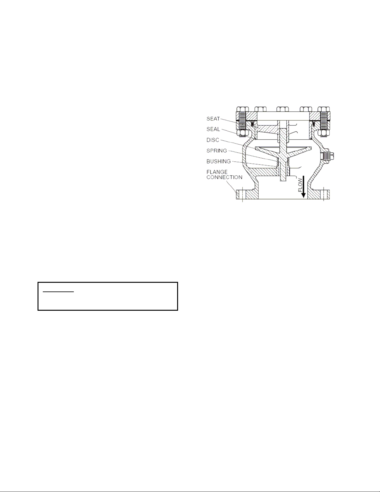
FIGURE 1. VACUUM BREAKER
DESCRIPTION OF OPERATION
The vacuum breaker is designed to prevent vacuum
conditions from occurring in pipes or tanks. After a
power failure or rapid draining of the system, a
vacuum condition often occurs in a pipe or tank.
The pressure difference between the inside vacuum
and outside air will cause a downward force on the
disc. At vacuum pressures greater than -0.25 psig,
the disc will compress the spring and move
downward allowing free flow of outside air into the
pipe or tank to eliminate the vacuum. When positive
pressure is restored in the pipe or tank, the valve will
automatically close and seal tightly. Optional valves
can be piped to the vacuum breaker to vent trapped
air in the pipeline if needed.
The valve may be supplied with either an optional
hooded outlet (not shown) or a flange for connection
to external piping or vent piping as shown in Figure
2. A flanged outlet is used when the valve vault is
subject to flooding or the vault cannot supply
sufficient air to the pipeline.
The only moving parts in the valve are the disc and
spring. The body bushing controls the movement of
the plug and assures that the plug contacts the seat
evenly. The valve has a resilient seal for drop tight
service.
1
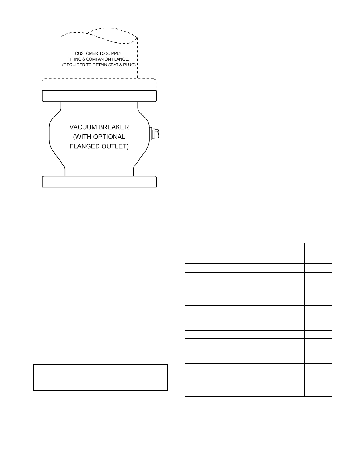
FIGURE 2. VACUUM BREAKER WITH
OPTIONAL FLANGE
INSTALLATION
The installation of the valve is important for its
proper operation. The seat end must be oriented
upward. The valve should be installed on top of
horizontal lines or tanks and equipped with an
isolation valve. If installed in a vault, adequate
ventilation is needed to supply air to the vacuum
breaker.
The valve should be installed to a standard flat-face
flange per ANSI B16.5 or AWWA C207.
When used with an outlet flange, special flange
requirements are given in Drawing SS-1381 on page
3. The mating flange inside diameter must overlap
the valve seat to provide proper seat retention.
Outlet piping and companion flange are required to
retain the seat and disc. Remove the ring flange
and 2 bolts supplied with the vacuum breaker, and
replace with external, full-size flanged piping.
WARNING: Vacuum Breakers with Flanged
When mating the check valve with butterfly isolation
valves, the clearance between the butterfly disc and
the fully open check valve stem must be checked.
Outlets must have outlet piping
installed or damage may occur.
The location of the stem is also shown on the
vacuum breaker submittal drawings. 10 inch and
smaller vacuum breakers have sufficient clearance
for most butterfly valves. However, on 12 inch and
larger valves, the shaft extends beyond the flange
face and may interfere with the operation of adjacent
valves. A short run of pipe or spacer may be
needed between the vacuum breaker and the
isolation valve.
FLANGED ENDS: The flange should be mated with
flat-faced pipe flanges equipped with resilient
gaskets. When ring gaskets are used, the bolt
material shall be ASTM A307 Grade B or SAE
Grade 2 Carbon Steel. Higher strength bolts should
only be used with full-face gaskets.
INSTALLATION: Lower valve over mating flange
using slings or chains around the valve body.
Lubricate the flange bolts and insert them around
the flange. Lightly turn bolts until gaps are
eliminated. The tightening of the bolts should then
be done in graduated steps using the cross-over
tightening method. Recommended lubricated
torques for use with resilient gaskets (75 durometer)
are given in Table 1.
If leakage occurs, allow gaskets to absorb fluid and
check torque and leakage after 24 hours. Do not
exceed bolt rating or crush gasket more than 50 per
cent of its thickness.
125# FLANGE DATA 250# FLANGE DATA
Valve
Size
(in)
2.5 5/8
3 5/8
4 5/8
5 3/4
6 3/4
8 3/4
10 7/8
12 7/8
14 1
16 1
18 1 1/8
20 1 1/8
24 1 1/4
30 1 1/4
36 1 1/2
42 1 1/2
Bolt
Dia.
(in)
Bolt
Torque
(ft-lbs)
25-75
25-75
30-90
30-90
30-90
40-120
45-150
65-200
80-250
90-300
100-350
120-450
150-500
180-600
250-750
300-900
Valve
Size
(in)
Bolt
Dia.
(in)
2.5 3/4
3 3/4
4 3/4
5 3/4
6 3/4
8 7/8
10 1
12 1 1/8
14 1 1/8
16 1 1/4
18 1 1/4
20 1 1/4
24 1 1/2
30 1 3/4
36 2
42 2
Bolt
Torque
(ft-lbs)
25-75
35-75
50-150
70-150
70-150
90-200
110-300
160-450
140-450
180-600
190-600
220-600
350-900
500-1500
700-2000
800-2500
TABLE 1. FLANGE BOLT TORQUES
2
 Loading...