

Val-Matic 2-12 in.Wafer Style Dual Disc Check Valve User Manual

Manual No.
DDCV-OM3-0
2-12 in. (DN 50-300 mm) Wafer Style
â
Dual Disc
Check Valve
Operation, Maintenance and
Installation Manual
INTRODUCTION.................................... 1
RECEIVING AND STORAGE ................ 1
DESCRIPTION OF OPERATION........... 1
INSTALLATION ..................................... 2
VALVE CONSTRUCTION...................... 3
MAINTENANCE..................................... 4
TROUBLESHOOTING...........................4
DISASSEMBLY...................................... 4
REASSEMBLY....................................... 4
PARTS AND SERVICE.......................... 5
WARRANTY .......................................... 5
®
VAL-MATIC® VALVE AND MANUFACTURING CORP.
905 RIVERSIDE DR. ELMHURST, IL. 60126
TEL. 630 / 941-7600 FAX. 630 / 941-8042
2-12 in. (DN 50-300 mm) WAFER STYLE DUAL DISCâ CHECK
VALVE OPERATION, MAINTENANCE AND INSTALLATION
INTRODUCTION
This manual will provide you with the information to
properly install and maintain the valve to ensure a
long service life. The Series 8800W Dual Disc
Check Valve is ruggedly constructed with bronze
discs and stainless steel trim to give years of trouble
free operation. The valve should be installed in
horizontal or vertical flow up pipes carrying clean
water. The valves can be equipped with special
springs for operation in blower air service (Series
8900W).
The Dual Disc
fully to provide flow in the forward direction and
close rapidly upon flow reversal. The valves are
used to prevent reverse flow through pumps or
piping systems. The size, cold working pressure,
model number, and year of manufacture are
stamped on the nameplate for reference.
This valve is not intended for fluids containing
suspended solids such as wastewater. For
wastewater and other high turbidity applications, use
Val-Matic Series 500 Swing-Flex
The valve is also not intended for hazardous fluids.
CAUTION: This valve is not intended for
â
Check Valve is designed to open
®
Check Valves.
fluids containing suspended
solids or hazardous fluids.
RECEIVING AND STORAGE
Inspect valves upon receipt for damage in shipment.
Unload all valves carefully to the ground without
dropping. When lifting, the valve should be secured
by the body and never lifted by the bronze or
stainless steel trim. Lifting eyebolts are provided on
NPS 10-12 (DN 250-300) valves.
The valves should remain boxed, clean and dry until
installed to prevent weather related damage. For
long term storage greater than six months, the
rubber surfaces of the seat (when provided) should
be coated with a thin film of FDA approved grease
such as Lubriko #CW-606. Do not expose rubber
seat to sunlight or ozone for any extended period.
â
FIGURE 1. DUAL DISC
â
CHECK VALVE
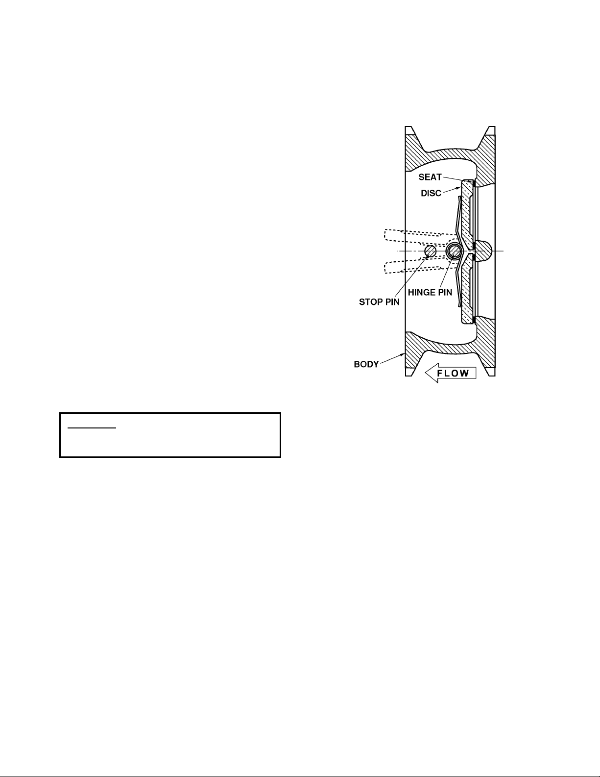
DESCRIPTION OF OPERATION
â
The Dual Disc
reverse flow automatically. On pump start-up, the
flow of water enters the valve from the seat end
(right side in Figure 1) and forces the two discs open
until they strike the disc stop pin. On pump shutdown, the torsion spring closes the disc before a
flow reversal takes place.
The valve body is supplied with compact wafer ends
as shown in Figure 1 for installation between mating
flanges.
The only moving parts in the valve are the discs and
spring. The discs and spring are guided in the body
with a hinge pin and a full open disc stop pin. The
pins are restrained in the body by stabilization
spheres to prevent vibration. The valve also has a
resilient seat for drop tight shut off.
Check Valve is designed to prevent
1
 Loading...