

Val-Matic 100S to 103S 1/2-3 Air Vacuum Valve User Manual

Manual No.
A/VV-OM1-1
½"-3" Air/Vacuum Valve
Models 100S to 103S
Operation, Maintenance and
Installation Manual
INTRODUCTION ....................................... 1
RECEIVING AND STORAGE.................... 1
DESCRIPTION OF OPERATION.............. 1
INSTALLATION......................................... 2
VALVE CONSTRUCTION......................... 2
MAINTENANCE ........................................ 2
TROUBLESHOOTING .............................. 3
DISASSEMBLY......................................... 3
REASSEMBLY.......................................... 3
PARTS & SERVICE .................................. 4
WARRANTY.............................................. 4
VALVE AND MANUFACTURING CORP.
905 Riverside Dr. ● Elmhurst, IL 60126
Phone (630) 941-7600 ● Fax (630) 941-8042
www.valmatic.com
VAL-MATIC'S ½"-3" AIR/VACUUM VALVE
OPERATION, MAINTENANCE AND INSTALLATION
I
NTRODUCTION
The Air/Vacuum Valve has been designed with
stainless steel trim to give years of trouble-free
operation. This manual will provide you with the
information to properly install and maintain the
valve to ensure a long service life. The
Air/Vacuum valve is designed to exhaust large
quantities of air upon system start-up and allow
air to re-enter the line upon system shut down.
NOTE: While Air/Vacuum Valves will exhaust
large quantities of air upon start-up, they will not
continuously release air during system
operation. For that function, an Air Release
Valve is required.
Also, this valve is not intended for fluids
containing suspended solids such as
wastewater. For waste-water and other high
turbidity applications, use Val-Matic Series 300A
Sewage Air/Vacuum Valves.
CAUTION: This valve is not intended
for fuel service or fluids
containing suspended
solids.
The valve is a float-operated, resilient-seated
valve designed to handle clean fluids. The Size,
Maximum Working Pressure, and Series No. are
stamped on the nameplate for reference.
RECEIVING AND STORAGE
Inspect valves upon receipt for damage in shipment. Unload all valves carefully to the ground
without dropping.
Valves should remain crated, clean and dry until
installed to prevent weather related damage.
For long term storage greater than six months,
the rubber surfaces of the seat should be coated
with a thin film of FDA approved grease such as
Lubriko #CW-606. Do not expose seat to
sunlight or ozone for any extended period.
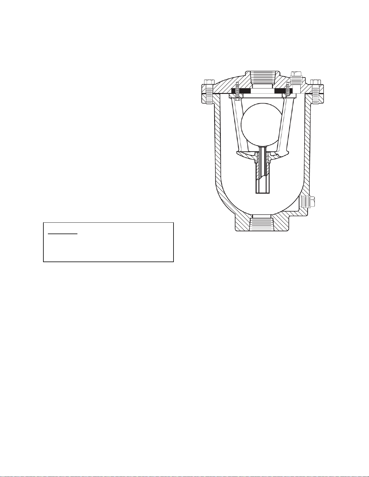
FIGURE 1. ½"-3" AIR/VACUUM VALVE
DESCRIPTION OF OPERATION
The Air/Vacuum Valve is designed to exhaust
large quantities of air upon system start-up and
allow air to re-enter the line upon system shutdown or line break. As water enters the valve
during start-up, the float will rise, closing the
outlet port. The valve will remain closed until
system pressure drops to near zero pressure. It
will open during shut-down to perform a dual
purpose. First, it eliminates the possibility of a
vacuum forming and a potential pipeline
collapse. Second it allows rapid drainage of the
line when system maintenance is required.
1
 Loading...