

Valmar MULTY P TTi Series, MULTY P 7 TTi, MULTY P 7 TTi+dual, MULTY P 12 TTi Handling, Operating And Maintenance Manual

VALMAR
HANDLING, OPERATING AND
MAINTENANCE GUIDE OF THE APPLIANCES
FOR THE PRODUCTION OF ICE CREAM
Model MULTY P TTi
Ver_MU_TT_001

2
Italian Gelato Concepts Pty Limited
PO Box 2134 Toowong Qld 4066
ABN 48 603 731 424
www.italiangelato.com.au
info@italiangelato.com.au
Mob: +61 (0) 411 089 142

3
TABLE OF CONTENTS
1 INSTRUCTIONS ON HOW TO USE THE GUIDE ...................................... 7
1.1
2 GENERAL FEATURES AND SPECIFICATIONS ....................................... 8
2.1
2.2
2.3
3 TRANSPORTATION AND PLACING OF THE APPLIANCE ................... 12
3.1
3.2
3.3
3.4
4 REQUIREMENTS AND CONDITIONS FOR NORMAL OPERATION OF
THE APPLIANCE ............................................................................................ 14
4.1
4.2
4.3
5 CONNECTING THE APPLIANCE ............................................................ 16
5.1
5.2
5.3
6 OPERATING THE APPLIANCE ............................................................... 18
7 CONTROL BOARD .................................................................................. 19
7.1
7.2
7.3
7.4
7.5
7.6
7.7
7.8
8 PROGRAMS ............................................................................................. 73
9 MENU PROGRAMS.................................................................................. 74
9.1
9.2
10 CHANGING PARAMETERS OF MACHINE ............................................. 87
10.1
10.2
11 PROTECTION OF THE USER AND OF THE MACHINE ......................... 99
11.1
11.2
11.3
11.4
12 USE OF THE APPLIANCE ..................................................................... 100
12.1
12.2
12.3
12.4
12.5
SYMBOLS USED IN THE GUIDE ........................................................ 7
GENERAL FEATURES ........................................................................ 8
IDENTIFICATION OF THE APPLIANCE ........................................... 10
TECHNICAL SPECIFICATIONS ........................................................ 11
INSTRUCTIONS FOR PREVENTING INJURIES .............................. 12
UNLOADING THE APPLIANCE FROM THE LORRY........................ 12
UNPACKING OF THE APPLIANCE ................................................... 13
PLACING THE APPLIANCE ON THE GROUND ............................... 13
ENVIRONMENTAL CONDITIONS ..................................................... 14
WATER SUPPLY REQUIREMENTS ................................................. 14
ELECTRICITY SUPPLY REQUIREMENTS ....................................... 15
INSTRUCTIONS FOR PREVENTION OF INJURIES ........................ 16
CONNECTING THE APPLIANCE TO THE WATER SUPPLY ........... 16
CONNECTING THE APPLIANCE TO THE POWER SUPPLY .......... 17
TOUCH SCREEN (dual inactive home screen) ................................. 19
PUSH-BUTTON PANEL (TREATING – HEATING) ........................... 49
PUSH-BUTTON PANEL (PRODUCTION – COOLING) ..................... 53
FIRST USING OF THE MACHINE ..................................................... 61
LANGUAGE SELECTION .................................................................. 62
DATA DOWNLOAD ........................................................................... 63
UPDATE OF NEW PROGRAM OR NEW DATABASE ...................... 71
WEAR OF THE SCRAPERS ............................................................. 72
MENU PROGRAMS of the HEATING PART ..................................... 74
MENU PROGRAMS of the COOLING PART ..................................... 80
CHANGING PARAMETERS (cooking part) ....................................... 87
CHANGING PARAMETERS (cooling part) ........................................ 93
PROTECTION OF THE USER........................................................... 99
ELECTRICAL OVERLOAD PROTECTION ........................................ 99
THERMIC SAFETY DEVICES ........................................................... 99
PROTECTION OF THE COOLING SYSTEM .................................... 99
INSTRUCTIONS FOR THE PREVENTION OF INJURIES .............. 100
BASIC RULES FOR OPERATING THE APPLIANCE...................... 101
COVER OF THE KETTLE ................................................................ 102
OUTLET VALVE .............................................................................. 102
PROCESSING CYLINDER DOOR .................................................. 103

4
12.6
OUTLET HOLE COVER .................................................................. 103
12.7
TO-DO LIST BEFORE OPERATING THE APPLIANCE .................. 104
13 CLEANING OF THE APPLIANCE .......................................................... 105
13.1
INSTRUCTIONS FOR THE PREVENTION OF INJURIES .............. 105
13.2
CLEANING THE SURFACES OF THE APPLIANCE ....................... 106
13.3
USING THE WATER PIPE FOR CLEANING ................................... 106
13.4
CLEANING OF PARTS THAT COME IN CONTACT WITH THE ICE
CREAM 107
13.5
13.6
DISINFECTION OF THE KETTLE ................................................... 130
DISINFECTION OF THE ICE CREAM PRODUCTION CYLINDER . 131
14 MAINTENANCE OF THE APPLIANCE .................................................. 131
14.1
INSTRUCTIONS FOR PREVENTION OF INJURIES ...................... 131
14.2
PROBLEMS, ERRORS AND TROUBLESHOOTING ...................... 132
14.3
REGULAR MAINTENANCE INSPECTION PLAN............................ 133
14.4
TEST RUN ....................................................................................... 133
14.5
CHECKING THE CONDITION AND WEAR OF THE MIXER
SCRAPERS .................................................................................................... 133
14.6
REPLACING THE MIXER SCRAPERS AND SLIDERS .................. 135
14.7
SETTING THE WATER REGULATION VALVE ............................... 137
14.8
DANGER OF TEMPERATURES BELOW 0 °C ............................... 138
14.9
ORDERING SPARE PARTS ............................................................ 139

5
BASIC STARTING OF THE MACHINE
STARTING OF THE MACHINE (heating at 85°C ):
• With quick key AUTOMATIC
AUTOMATIC - button for the heating of the mixture up to 85°C.
STARTING OF THE MACHINE (ice cream production)
• With quick key ICE CREAM
ICE CREAM - button for the producing of the ice cream in MODE 1.
STARTING OF THE MACHINE (extraction of the ice cream)
• With key EXTRACTION
EXTRACTION - button for the extraction of the ice cream.
For more information read the entrie manual!

6
HOT AREA!
PAY PARTICUAL ATTENTION - HOT MIXTURE!
Duiring the heating operation (hot mixture) or after emptying of it (time 10
minutes) the user:
can only by handle slowly opened or closed the outlet valve!
can turn the handle in clockwise direction (for opening and closing the
outlet pipe)!
can’t apprehended or turn the inox part of the outlet pipe!
The user must take particular attention when slow opening and closing the
outlet pipe (the cover of the batch feeder must be closed) that does’n the hot
mixture burned the hands, face...!

7
1 INSTRUCTIONS ON HOW TO USE THE GUIDE
Since we are in the company VALMAR aware that it is in yours as well as in our
interest that the machine would operate at its best and as cheap as possible we
have prepared this instruction manual, in order to assist you with your machine.
The instruction manual must be stored near the machine, so you will be able to
access it when needed.
Only authorized persons (operators), who know how to operate the appliance,
are allowed to handle and operate it. Operators must read and study the
manual carefully and they must follow the instructions.
The company VALMAR can not be held responsible for any kind of damage or
injuries occurred due to non-consideration of the instruction manual.
Further to these instructions, all applicable environmental legislation and
regulations regarding safety at work must be taken into consideration.
Handling the appliance required carefulness, which is expressed in the manual
with symbols.
1.1 SYMBOLS USED IN THE GUIDE
This symbol represents important content in the manual. You should study the
text accompanied with this symbol carefully. Disregard of instructions and
warning symbols may lead to serious personal injury and damage to the
appliance.
This symbol represents explicit prohibition of specific actions or operations.
When you see this symbol, special attention should be paid to what it refers.
This symbol calls your attention to the importance of the text as regards proper
handling of the appliance, but without danger of personal injury.
This symbol means that the content of the text is of a technical nature and is
related to technical specifications.
This symbol is an instruction to proceed with caution while engaging in a
specific operation referred to in the text.
This symbol means that the action to which it refers may also be carried out by
persons skilled in the operation of the appliance.

8
This symbol is a warning that any action or operation referred to in the text must
be carried out only by authorized servicing personnel.
2 GENERAL FEATURES AND SPECIFICATIONS
2.1 GENERAL FEATURES
The appliance is designed exclusively for the ice cream and other mass
(custard...) production and the processing of fresh ice cream. The
manufacturing company VALMAR cannot be held liable in any way for personal
injuries or damage caused to the appliance in cases when the appliance has
been used for any other purposes than those specified.
The appliance consists of:
main construction
side panels and top cover
mixture producing cylinder with mixer
electrical assembly
hydraulic assembly (water)
cooling assembly
It is forbidden to reassemble, alter or in any way modify the appliance or any
part of the appliance without an express permission of the manufacturer.
This appliance is designed in compliance with the following European
directives:
CEE 2006/42/EC and updates,
CEE 2006/95/EC and updates,
CEE 2004/108/EC and updates,
CEE 89/109 and updates,
CEE 1935/2004 and updates,
CEE 2023/2006 and updates,
CEE 72/2002 and updates.
and following standards:
EN ISO 12100-2:2003+A1:2009
EN 60204:2006+A1:2009
EN ISO 14121-1:2007
EN ISO 13857:2008
EN 61310-1 + EN 61310-2
EN ISO 14159
This appliance is fully compliant with all legal standards for operational safety.
The level of operating noise does not exceed 75 dB (in front of the machine).
Cooling is carried out with the use of ecological gas (see the silver plate on the
back side of the machine) and water condenser with the possibility of mounting
air condenser.

9
With the intention to provide our customers with a well-tested appliance, ready
for normal operation, the initial start-up is always carried out at the factory by
the manufacturer before the product is packed and shipped to our client.
Additional start-up and appliance's adjustments can be made on the client's
premises by technicians authorized by VALMAR.Set the appliance in a suitable
place, block it to ensure stability, and connect to the water and power supplies.
Blocked and connected appliance is ready for operation.
The price of the appliance does not include installation costs and the cost of the
demonstration of its operation.
The warranty does not include replacements or repairs of malfunctions caused
by incorrect connection of the appliance.
The quality and the quantity of the ice cream depend on:
temperature of the cooling water;
temperature of air;
final temperature of the ice cream;
quantity and quality of the ice cream mixture;
desired consistency of ice cream;
increase in the volume of ice cream.
The mixture is poured into the treating cylinder and then pressing AUTOMATIC
key. The mixture is heated up to treating temperature (85°C) and then
maintained at treating temperature until is poured into processing cylinder.
Hot mixture is introduced inside the production cylinder. The production of ice
cream - mass is started by pressing the ICE CREAM key or START key.
The machine cools the mixture (mass, ice cream) until the final density (or up to
the final temperature or the preset time) of ice cream.
DUAL machine can heating and cooling some mixture or cream in production
cylinder by pressing the START key (actual program).
Ice cream, mass is extraced out through the ejection hole into the vessel by
pressing EXTRACTION key.
Operations of the appliance:
Kettle - heating part:
mixing and heating the mixture in the treating cylinder up to the
predetermined temperature (85°C) and then maintenance at the
predetermined temperature (AUTOMATIC HEATING ),
Caution must be taken because the outlet valve and the pipe are
heated because they are exposed at hot mixture. Danger of scalding!
mixing and heating the mixture in the cylinder of preparation up to the
selected temperature trough the selected program (START );
Caution must be taken because the outlet valve and the pipe are
heated because they are exposed at hot mixture. Danger of scalding!
mixing in the mixture treating cylinder (MIXING, CLEANING,
DESINFECTING, TESTING START UP );
Cylinder - cooling part:
mixing and cooling of the ice cream mixture in the production cylinder
in trough the selected program (quick button) ;
mixing and cooling of the cream mixture in the production cylinder in
trough the selected program (START );
mixing and heating or colling of the mixture, cream in the production
cylinder in trought the selected program (START ) - only DUAL
MACHINES;
fast mixing – extraction of the ice cream in the production cylinder
(EXTRACTION );
slow mixing in the production cylinder (MIXING, CLEANING,
DESINFECTING, TESTING START UP ).
The warranty does not include replacements or repairs of malfunctions caused
by incorrect use of the appliance.
2.2 IDENTIFICATION OF THE APPLIANCE
Every appliance has its own identification label, which is fixed on the backside
of the appliance.
The ID label contains the essential technical specifications of the appliance:
1. manufacturer
2. manufacturers address
3. model
4. serial number
5. power supply voltage
6. nominal frequency
7. maximum current
8. cooling gas type
9. cooling gas weight
10. power
11. year of manufacturing
10

MODEL
WATER FLUX
PRODUCTION OF
SINGLE QUANTITY
1
2
3
5
8
6
9
4
7
10
11
The ID label must not be removed or damaged!
2.3 TECHNICAL SPECIFICATIONS
The appliances essential technical specifications:
power supply voltage (see appliance label)
maximum current (see appliance label)
power (see appliance label)
nominal frequency (see appliance label)
water consumption
production capacity
capacity of a cylinder cycle
weight
dimensions
All technical specifications, such as the weight, dimensions and power of the
appliance are not mandatory for the manufacturer and may change.
MULTY P
7 TTi 613 709+241 1401+100 11 17 9/45 2 7
7 TTi+dual
12 TTi 613 709+241 1401+100 15,34
WEIGHT
Kg Leight Depth Height KW * l/ciklus Kg/h Min kg Max kg
613 709+241 1401+100 11,7 17 9/45 2 7
DIMENSION (mm) POWER
cca
21 12/75 3 10
ICE-CREAM
VOLUME/CYCLE
11

Note that 1 liter of ice cream mixture is equivalent to 1,1 kilogram.
*
The water consumption in cylinder depends on:
the incoming water temperature,
the ice cream mixture (type),
the ice cream mixture temperature,
the required final ice cream temperature.
3 TRANSPORTATION AND PLACING OF THE
APPLIANCE
3.1 INSTRUCTIONS FOR PREVENTING INJURIES
Pay due attention to legally required safety measures.
At work wear suitable clothing. Do not wear ties, jeweller’s chains or belts,
which could get caught in the machine.
Do not shift or dislocate the safety switches or protective parts.
Make sure that the lifting device is in good condition and that its load capacity
exceeds the weight of the appliance (refer to the technical specifications data
sheet).
Lift the appliance following the instructions for its use and maintenance. Pay
attention to the handling and handgrip locations. The use of a suitable lifting
device is recommended.
While lifting or moving the appliance do not stand under the machine.
Do not turn the appliance after holding the cables or the water hose has lifted it.
If you have to attend to any work higher up above the appliance, you should use
a suitable ladder and not the appliance for support.
3.2 UNLOADING THE APPLIANCE FROM THE LORRY
Required devices are a hand lift for pallets and a forklift truck with load capacity
of at least 1,200 kg.
Lift the crate containing the appliance using the hydraulic palette lift and move it
as close to the open side of the lorry as possible.
12

Remove the hand lift from underneath and handle the crate with the forklift
truck. Make sure that the weight is focused on the holding points.
Remove the crate from the lorry with the forklift truck in reverse gear as soon as
the crate is moved out of the lorry, and lower the crate to the minimal height of
around 30 cm.
Slowly and carefully place the box containing the appliance in its place. To
move the appliance around on the premises use wheels, which are supplied
with the appliance.
3.3 UNPACKING OF THE APPLIANCE
Upon the delivery check if the crate was not damaged during transportation.
First the appliance is fixed on the pallet with two paking strips and then is
placed the carton box which is fixed to the pallet with two paking strip too.
When the machine is unpacked, make sure that the packaging is disposed in a
suitable manner and in compliance with standards on environmental safety.
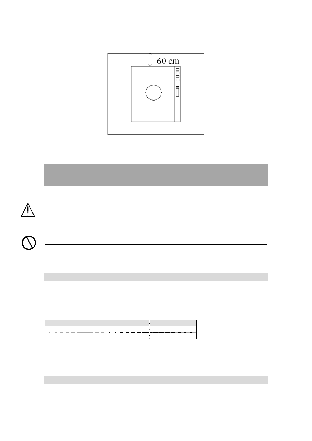
3.4 PLACING THE APPLIANCE ON THE GROUND
Place the machine on a level solid non-combustible surface with an adequate
strength of at least 600 kg per m² for the weight of the machine, and position the
appliance at least 60 cm away from the wall or other objects. Leave enough
space in front of the appliance to ensure comfortable access and work with the
appliance.
13
min.
max.
While placing the appliance in position, block the front wheels (by pressing the
brake), which will ensure that the appliance will not be able to move.
4 REQUIREMENTS AND CONDITIONS FOR
NORMAL OPERATION OF THE APPLIANCE
Before connecting the appliance to electricity supply, the operator must make
sure that environment requirements have been met: the temperature and
humidity of the air must be appropriate and the water supply and electricity
networks comply with all requirements for normal operation of the appliance.
When the characteristics of either the water supply or electricity network fail to
meet the requirements for normal operation, the machine must not be
connected to power supply.
4.1 ENVIRONMENTAL CONDITIONS
Prior to connecting the appliance, the temperature and the humidity of the
environment, in which the appliance will be operated, must be assessed and
checked.
AIR TEMPERATURE 10°C 38°C
AIR HUMIDITY 0% 85%
If room temperature drops under 0 ºC (273K), water must be released from the
condenser.
4.2 WATER SUPPLY REQUIREMENTS
14

Prior to connecting the appliance to the power source, the temperature,
min.
max.
nominal voltage
min. voltage
max. voltage
nominal voltage
min. voltage
max. voltage
nominal voltage
min. vol
tage
max. voltage
nominal voltage
min. voltage
max. voltage
nominal voltage
min. voltage
max. voltage
pressure and water flow from the water supply network must be checked.
Permitted water temperature and water pressure from the water supply network:
WATER TEMPERATURE
WATER PRESSURE 100kPa (1bar) 800kPa (8bar)
WATER FLOW 400 l/h /
5°C 30°C
Water supply must be checked for all conditions that are required for alimentary
use.
Low water pressure causes the cooling system to function improperly. The
cooling gas does not condense, thus causing the compressor to overload. In
such cases, the safety pressure valve kicks in and switches off the compressor.
The results of mixture treating and ice cream production when the water
pressure is too low are not as good as when the water pressure is normal.
The maximum presence of chlorides in water is 120 ppm. Exchangers are not
suitable for the use of salt water.
4.3 ELECTRICITY SUPPLY REQUIREMENTS
Prior to connecting the appliance to the power source, the voltage and the
maximum power current allowed in the network must be checked and the
appliance must be protected externally with FUSES and the MAIN SWITCH.
Permitted voltage of three-phase appliances (400/50/3):
400V 380V (400V–5%) 420V (400V+5%)
Permitted voltage of three-phase appliances (230/50/3):
230V 220V (230V–5%) 240V (230V+5%)
Permitted voltage of one-phase appliances (230/50/1):
230V 220V (230V–5%) 240V (230V+5%)
Permitted voltage of one-phase appliances (208-220/60/3):
208-220V 208V 220V
Permitted voltage of one-phase appliances (208-220/60/1):
208-220V 208V 220V
The diameter of each phase conductor must be of an appropriate dimension
(corresponding to the power of the fuses).
15

The MAIN SWITCH must be installed in the immediate vicinity of the appliance,
model
max. current
fuse type
where it must be easily visible, accessible to the operator and appropriately
marked.
Magnetothermic differential FUSES (slot ≥ 3 mm) of appropriate dimensions
must be installed between the electricity network and the MAIN SWITCH.
MULTY P 5 TTi (one-phase) 230V/50-60Hz/1ph 32 A SLOW
MULTY P 7 TTi (one-phase) 230V/50-60Hz/1ph 32 A SLOW
MULTY P 7 TTI (three-phase) 400V/50-60Hz/3ph 25 A SLOW
MULTY P 12 TTi (three-phase) 400V/50-60Hz/3ph 32 A SLOW
MULTY P 12 TTi (three-phase) 230V/50-60Hz/3ph 50 A SLOW
The position of the MAIN SWITCH with the FUSES in the power circuit scheme
of the appliance:
5 CONNECTING THE APPLIANCE
5.1 INSTRUCTIONS FOR PREVENTION OF INJURIES
When the characteristics of either the water supply or electricity network fail to
meet the requirements for normal operation, the machine must not be
connected to the power supply.
It is forbidden to connect the appliance to the power source when the floor
around the appliance is wet.
It is forbidden to connect the appliance to the power source if any of the side
panels and the cover is missing.
5.2 CONNECTING THE APPLIANCE TO THE WATER SUPPLY
The water supply regulation valve is connected to the WATER SUPPLY PORT.
The water outlet pipe is connected to the WATER OUTLET PORT and to the
outlet pipe leading to the drain. All these terminals have a diameter of 3/4" and
are located on the backside of the machine.
To connect the appliance to the water supply (water supply port) and the outlet
to the drain (water outlet port), use pipes capable of withstanding 1MPa and
measuring at least ½” in diameter (make sure upon the delivery that the pipes
are supplied with the appliance).
16

WATTER SUPPLY PORT
(condenser)
WATER OUTLET PORT
(condenser)
WATTER SUPPLY PORT (pipe – drinkable water)
If the appliance is meant to be used in areas with two separate water supplies,
two separate water connectors are built in it, one for each: a DRINKING
WATER SUPPLY PORT and a COOLING WATER SUPPLY PORT
(condenser).
The valve belonging to the cooling water supply must not be connected to the
DRINKING WATER SUPPLY PORT.
The valve belonging to the drinking water supply may be connected to the
COOLING WATER SUPPLY PORT and/or to the DRINKING WATER SUPPLY
PORT.
The valve should be opened after the appliance has been connected to the
water supply system.
5.3 CONNECTING THE APPLIANCE TO THE POWER SUPPLY
Only appropriately trained technicians are allowed to connect the appliance to
the electrical current. They must follow installation instructions and observe the
occupational safety regulations applying in the country in which the appliance is
being installed. They must read the instructions carefully and above all
thoroughly familiarize themselves with the sections on REQUIREMENTS AND
CONDITIONS FOR NORMAL OPERATION OF THE APPLIANCE and the
machine’s electrical circuit scheme.
Before connecting the appliance, all attachments that might have become loose
during transportation must be checked. Attachments that may have become
loose or disconnected must be screwed back on and tightened.
Connecting instructions for three-vein cable (one-phase appliances – 230/50/1
or 208-220/60/1):
phase type colour
L1 208-220 or 230 V ~ brown
N 208-220 or 230 V ~ blue
PE ground yellow-green
Connecting instructions for four-vein cable (three-phase appliances – 230/50/3
or 208-220/60/3):
phase type colour
L1 208-220 or 230 V ~ black
L2 208-220 or 230 V ~ brown
L3 208-220 or 230 V ~ grey
17
PE ground yellow-green

Connecting instructions for five-vein cable (three-phase appliances – 400/50/3):
phase type color
L1 400 V ~ black
L2 400 V ~ brown
L3 400 V ~ grey
N neutral blue
PE ground yellow-green
A test start-up of the appliance is carried out by an appropriately trained
electrician who has also connected the machine so as to make sure that it is
properly connected (see the section on MAINTENANCE).
If the machine has been connected correctly, the mixer in the mixture-treating
cylinder will rotate anti - clockwise.
Should the mixers rotate in the wrong direction, it is necessary to change the
connecting position of any of the two phases.
Production cylinder mixer, installed in appliances with built-in inverter, will rotate
in the correct direction regardless of the connecting position of either of the
phases so it is necesary check the direction of the mixer in the cooking cylinder.
The mixer must rotate in clockwise direction.
Should the mixers rotate in the wrong direction, it is necessary to change the
connecting position of any of the two phases.
After connecting the appliance to the electricity network, appropriately trained
electrician must also control the power consumption. The current must not
exceed the maximum allowed on the identification plate or sticker (see the
section GENERAL FEATURES AND SPECIFICATIONS).
6 OPERATING THE APPLIANCE
The user operates the appliance standing in front of appliance. This position
allows user to handle the control panel, the safety switch and the water flow
regulation valve (shower).
The appliance must be always under users control during operation.
18

CONTROL
BOARD
WATER PIPE
(DRINKABLE WATER)
EMERGENCY STOP SWITCH
WATER VALVE
The control panel is used to:
• display the status or the operation phase;
• perform the settings;
• to show messages and errors.
The emergency stop switch is used to safely and securely switch of the
electronics. The electronics is switched off by pressing down the switch-off key
in the normal position and then depressing it. The switch will normally remain
down and must be pulled back up by hand to return to its normal position.
The shower is used for cleaning of the appliance.
7 CONTROL BOARD
Control panel is composed from mixture treating – heating control panel and
cooling cream processing control.
7.1 TOUCH SCREEN (dual inactive home screen)
19

7.1.1 TOUCH SCREEN OF THE KETTLE
3
4
7.1.1.1 TOUCH SCREEN (dual inactive home screen left - kettle part)
1
2
DESCRIPTION:
TUTOR MESSAGES help users giving them instructions
and information about the processing. They also provide
1
information on any errors and give warnings on
operations. This message refers to upper – kettle part of
the machine.
Press the left part of display
2
(kettle) to enter in the single
inactive home screen.
7.1.1.2 Inactive (kettle) home screen:
1
2
20

DESCRIPTION:
6 9
11
10
1
TUTOR MESSAGES help users giving them instructions
and information about the processing. They also provide
information on any errors and give warnings on
operations.
2
POSITION OF THE MACHINE (standby).
3
Use this button to enter in the
SETTING MENU
4
QUICK PROGRMS KEYS.
7.1.1.3 Setting menu screen:
1
2
3
4
5
8
7
21

DESCRIPTION:
1
Use this function to enter the
PROGRAM MENU
2
Use this function to enter
MACHINE PARAMETERS
3
Use this function to enter
LANGUAGE SELECTION
4
Function to be used only by
Valmar technicians
Use this function to enter in
PASSWORD screen.
5
Digit password to
LOCK/UNLOCK the activities of
the machine.
Use this function to enter the
electronic info sheet and check
6
electronic sheet data: number,
latest update, software version,
etc.
Use this function to enter, check
and change settings such as
7
date, time, units of
measurement
(Celsius/Fahrenheit,
liters/gallons) or water quantity
8
Press the BACK button to return
to the previous screen
22

Press the HOME button to
1
4
2
3
5
6
7
8
9
10
11
12
9
return to the dual inactive home
screen.
For technician - net connection.
10
By correct code you can access
to connection between touch
screen and computer, TV…
Use this function to enter in
PASSWORD screen. Digit
11
password to RESET factory
settings (cancel all changes). All
saved values will be cleared.
7.1.1.4 Info menu screen:
DESCRIPTION:
1
2
3
4
5
6
Type of the machine.
Number of the data base.
The date of the last update.
Serial number of the electronic.
IP number.
MAC address (media access control address)
23

7
6
11 14 15
8
9
10
11
12
7.1.1.5 Setting screen:
Number of the software.
Version – number of the firmware (relay board).
Total hours of the working.
Total hours of the standbay.
Press BACK to return to the previous screen.
Press HOME to return to the main screen.
3
1
2
4
5
16
DESCRIPTION:
1
2
3
4
5
13
Year setting.
Time setting.
Month setting.
Minutes setting.
Day setting.
12
10
7
8
9
6
Liter/Gallon setting.
24

7
8
9
10
11
12
13
14
15
Beep volume setting.
Button volume setting.
Press BACK to return to the previous page.
Press HOME to return to the dual inactive home screen.
Water flow calibration (only sweety machine).
Celsius/Fahrenheit temperature setting.
Save new settings.
DOWN BUTTON decreased the actual value.
ACTUAL VALUES.
16
In the SETTINGS screen you can set the following parameters:
1. DATE: year month day ;
2. TIME: hours minutes ;
3. WATER UNIT OF MEASUREMENT: liters or gallons
4. TEMPERATURE UNIT OF MEASUREMENT: (celsius or
fahrenheit);
5. BEEP VOLUME ;
6. BUTTON VOLUME: .
DESCRIPTION:
UP BUTTON increased the actual value.
Press the button. Set the current year
on the display by using the
arrows. Confirm with the button.
Factory default – central European time
zone.
25

Press the button. Set the current month
on the display by using the
arrows. Confirm with the button.
Factory default – central European time
zone
Press the button. Set the current day
on the display by using the arrows.
Confirm with the button.
Factory default – central European time
zone.
Press to activate the hour button. Set
the hour on the display by using
the arrows. Confirm with the
button.
Factory default (AUT.) – central European
time zone with automatic adjustment of the
winter and summer time.
Two possibilities normal or AUT.
Press to activate the minutes button.
Set the minutes on the display by using
the arrows. Confirm with the
button.
Factory default – central European time
zone.
Press the button. Select liters or
gallons as unit of measurement by using the
arrows. Confirm with the button.
Factory default – liters.
26

2
9
Press the button. Select Celsius or
Fahrenheit as unit of measurement by using
the arrows. Confirm with the
button.
Factory default – Celsius.
Press the button. Adjust the volume
of the signal by using the arrows.
Confirm with the button.
Factory default – value 100.
Press the button. Adjust the volume
of the button by using the arrows.
Confirm with the button.
Factory default – value 70.
Program menu screen:
1
13
12
11
10
DESCRIPTION:
1
3
4
5
6
7
8
ICE CREAM PROGRAM MENU
Select the MILK button to enter the list of programs for milk
ice cream.
27

2
3
4
5
6
7
SORBET, SLUSH, FRUIT SAUCE AND TOPPING
PROGRAM MENU
Select the FRUIT button to enter the list of programs for
fruit sorbets, slush and sugar syrups.
PROGRAM MENU FOR CHOCOLATE ICE CREAM AND
OTHER CHOCOLATE PRODUCTS
Select the CHOCO button to enter the list of programs for
chocolate ice cream, toppings, sauces, ganache, creams,
etc..
PROGRAM MENU FOR CHOCOLATE ICE CREAM AND
OTHER CHOCOLATE PRODUCTS
Select the CHOCO button to enter the list of programs for
chocolate ice cream, toppings, sauces, ganache, creams,
etc..
CUSTOMIZED PROGRAM MENU FOR ICE CREAM,
SORBETS, PASTRY AND GASTRONOMY PRODUCTS
Select the CUSTOM button to enter the list of customizable
programs.
FOOD AND GASTRONOMY PROGRAM MENU
Select the GASTRO button to enter the list of food
programs such as soups, minestrone, polenta, risotto,
sauces, béchamel sauce, stew, etc..
PROGRAM NAME
8
9
10
11
12
....
13
FACTORY MENU
Select the FACTORY PROGRAMS button to enter the list
of programs for special functions such as variegated ice
cream extractions, mixing, etc.
Press BACK to return to the previous screen.
Press HOME to return to the dual inactive home screen.
PROGRAM NUMBER.
LAST used or NEW selected program.
TUTOR MESSAGES help users giving them instructions
and information about the processing. They also provide
information on any errors and give warnings on operations.
28

7.1.1.6 Program list screen:
7
10
11
DESCRIPTION:
1
TUTOR MESSAGES help users giving them instructions
and information about the processing. They also provide
information on any errors and give warnings on operations.
2
Program name and number.
1
2
3
4
5
9
8
6
3
4
5
6
7
8
Selected program. When pressed, the button changes color
and becomes black.
Button UP to scroll the program list.
Button DOWN to scroll the program list.
NOT ACTIVE Press the button to enter the step settings
screen. NOT ACTIVE To be used only by Valmar
technicians.
Press here to have a short program
description.
Press OK to confirm the selected program.
29

4
9
Press CHANGE to set the program and link it with one of the
four hot start buttons on the push-button panel and on the
main display.
10
Press BACK to return to the previous screen.
11
7.1.1.7 Program list tekst screen:
Press HOME to return to the dual inactive home screen..
1
2
1
2
...
3
4
2
3
Program description text
Cursor UP and DOWN.
Use the arrows to scroll the text
Press BACK to return to the previous screen
Press HOME to return to the dual inactive home screen.
Press the program info button to have a description of the selected program and
information on how to use it.
30

7.1.1.8 Active program screen:
2
1
11
DESCRIPTION:
1
PLUS button. Select this button to
enter in additional display.
10
4 3
5
6
9
8
7
2
3
4
5
6
7
8
PROGRAM NUMBER.
SET button.
Select this button to enter in
programs parameters of current
step.
PROGRAM NAME.
TUTOR MESSAGES help users giving them instructions
and information about the processing. They also provide
information on any errors and give warnings on operations.
Press BACK to return to the previous screen.
BUTTON SNAIL decreased the actual speed. If the button is
grey the decreasing is not allowed.
MIXER SPEED DISPLAY.
31

9
1
6
BUTTON ROCKET increased the actual speed. If the button
is grey the increasing is not possible.
10
PRODUCTION MODE DISPLAY.
11
TIME DISPLAY.
If the operator not operating (push) on active program screen the
machine after a few seconds change it with the active single home screen:
For returned on active program screen click anywhere on the single active
home screen.
7.1.1.9 Additional active programs screen:
8
7
2
5
4
3
32

DESCRIPTION
1
2
3
4
5
TUTOR MESSAGES help users giving them instructions
and information about the processing. They also provide
information on any errors and give warnings on operations.
PROGRAM NUMBER.
PROGRAM NAME.
Press the button to enter the
parameters screen (only for
Valmar technicians).
Press BACK to return to the previous screen.
6
Press HOME to return to the dual inactive home screen..
10
Press info to have a short program
description.
11
STEP NUMBER.
7.1.1.10 Active program parameters screen:
1
2
7
3
4
DESCRIPTION:
6
5
33

1
2
3
4
5
6
7
In programs (heating) when you change the value you change the value in
active step. When the actual step is finished the machine alerts us with an
audile signal and the new note of the steep is show on TUTOR MESSAGE.
7.1.2 TOUCH SCREEN OF THE CYLINDER
7.1.2.1 TOUCH SCREEN (dual inactive home screen right - cylinder part)
1
TUTOR MESSAGES help users giving them instructions
and information about the processing. They also provide
information on any errors and give warnings on operations.
UP BUTTON increased the actual value. If the button is grey
the increasing is not allowed.
TEMPERATURE DISPLAY – actual values.
CONFIREM BUTTON confirmed the selected value. If the
button is grey the confirmation is not allowed.
DOWN BUTTON decreased the actual value. If the button is
grey the decreasing is not allowed.
Press BACK to return to the previous screen
TIME DISPLAY – actual values.
2
DESCRIPTION:
1
4
34
TUTOR MESSAGES help users giving them instructions
and information about the processing. They also provide
information on any errors and give warnings on
operations. This message refers to upper – kettle part of
the machine.
Press the right part of display
(cylinder) to enter in the single
inactive home screen.

7.1.2.2 Inactive home screen:
6 9
11
10
3
4
1
DESCRIPTION:
TUTOR MESSAGES help users giving them instructions
1
and information about the processing. They also provide
information on any errors and give warnings on
operations.
2
2
POSITION OF THE MACHINE (standby).
3
Use this button to enter in the
SETTINGS MENU
4
QUICK PROGRMS KEYS.
7.1.2.3 Settings menu screen:
1
2
3
4
8
7
35
5

DESCRIPTION:
1
2
3
4
Use this function to enter the
PROGRAM MENU
Use this function to enter
MACHINE PARAMETERS
Use this function to enter
LANGUAGE SELECTION
Function to be used only by
Valmar technicians
Use this function to enter in
PASSWORD screen.
5
6
7
Digit password to
LOCK/UNLOCK the activities of
the machine.
Use this function to enter the
electronic info sheet and check
electronic sheet data: number,
latest update, software version,
etc.
Use this function to enter, check
and change settings such as
date, time, units of
measurement
(Celsius/Fahrenheit,
liters/gallons) or water quantity
8
36
Press the BACK button to return
to the previous screen

Press the HOME button to
1
4
2
3
5
6
7
8
9
10
11 12
9
return to the dual inactive home
screen.
For technician - net connection.
10
By correct code you can access
to connection between touch
screen and computer, TV…
Use this function to enter in
PASSWORD screen. Digit
11
password to RESET factory
settings (cancel all changes). All
saved values will be cleared.
7.1.2.4 Info menu screen:
DESCRIPTION:
1
2
3
4
5
6
7
8
Type of the machine.
Number of the data base.
The date of the last update.
Serial number of the electronic.
IP number.
MAC address (media access control address)
Number of the software.
Version – number of the firmware (relay board).
37

6
11 14 15
9
10
11
12
7.1.2.5 Setting screen:
Total hours of the working.
Total hours of the standbay.
Press BACK to return to the previous screen.
Press HOME to return to the main screen.
3
1
5
2
4
16
DESCRIPTION:
1
2
3
4
5
13
Year setting.
Time setting.
Month setting.
Minutes setting.
Day setting.
12
10
7
8
9
6
Liter/Gallon setting.
7
Beep volume setting.
8
Button volume setting.
38

9
10
11
12
13
14
15
16
In the SETTINGS screen you can set the following parameters:
Press BACK to return to the previous page.
Press HOME to return to the dual inactive home screen.
Water flow calibration (only sweety machine).
Celsius/Fahrenheit temperature setting.
Save new settings.
DOWN BUTTON decreased the actual value.
ACTUAL VALUES.
UP BUTTON increased the actual value.
1. DATE: year month day ;
2. TIME: hours minutes ;
3. WATER UNIT OF MEASUREMENT: liters or gallons
4. TEMPERATURE UNIT OF MEASUREMENT: (celsius or
fahrenheit);
5. BEEP VOLUME ;
6. BUTTON VOLUME: .
DESCRIPTION:
Press the button. Set the current year
on the display by using the
arrows. Confirm with the button.
Factory default – central European time
zone.
Press the button. Set the current month
on the display by using the
arrows. Confirm with the button.
Factory default – central European time
zone
39

Press the button. Set the current day
on the display by using the arrows.
Confirm with the button.
Factory default – central European time
zone.
Press to activate the hour button. Set
the hour on the display by using
the arrows. Confirm with the
button.
Factory default (AUT.) – central European
time zone with automatic adjustment of the
winter and summer time.
Two possibilities normal or AUT.
Press to activate the minutes button.
Set the minutes on the display by using
the arrows. Confirm with the
button.
Factory default – central European time
zone.
Press the button. Select liters or
gallons as unit of measurement by using the
arrows. Confirm with the button.
Factory default – liters.
Press the button. Select Celsius or
Fahrenheit as unit of measurement by using
the arrows. Confirm with the
button.
Factory default – Celsius.
40

2
9
7.1.2.6 Program menu screen:
1
13
Press the button. Adjust the volume
of the signal by using the arrows.
Confirm with the button.
Factory default – value 100.
Press the button. Adjust the volume
of the button by using the arrows.
Confirm with the button.
Factory default – value 70.
3
4
5
6
12
11
10
DESCRIPTION:
1
2
3
7
8
ICE CREAM PROGRAM MENU
Select the MILK button to enter the list of programs for milk
ice cream.
SORBET, SLUSH, FRUIT SAUCE AND TOPPING
PROGRAM MENU
Select the FRUIT button to enter the list of programs for
fruit sorbets, slush and sugar syrups.
PROGRAM MENU FOR CHOCOLATE ICE CREAM AND
OTHER CHOCOLATE PRODUCTS
Select the CHOCO button to enter the list of programs for
chocolate ice cream, toppings, sauces, ganache, creams,
etc..
41

4
5
6
7
8
9
PROGRAM MENU FOR CHOCOLATE ICE CREAM AND
OTHER CHOCOLATE PRODUCTS
Select the CHOCO button to enter the list of programs for
chocolate ice cream, toppings, sauces, ganache, creams,
etc..
CUSTOMIZED PROGRAM MENU FOR ICE CREAM,
SORBETS, PASTRY AND GASTRONOMY PRODUCTS
Select the CUSTOM button to enter the list of customizable
programs and programs for ice cream production in mode
2, mode 3 and mode 4.
FOOD AND GASTRONOMY PROGRAM MENU
Select the GASTRO button to enter the list of food
programs such as soups, minestrone, polenta, risotto,
sauces, béchamel sauce, stew, etc..
PROGRAM NAME
FACTORY MENU
Select the FACTORY PROGRAMS button to enter the list
of programs for special functions such as variegated ice
cream extractions, variable speed ice cream extraction,
mixing, etc.
Press BACK to return to the previous screen.
10
11
12
....
13
Press HOME to return to the dual inactive home screen.
PROGRAM NUMBER.
LAST used or NEW selected program.
TUTOR MESSAGES help users giving them instructions
and information about the processing. They also provide
information on any errors and give warnings on operations.
42

7.1.2.7 Program list screen:
7
10
11
DESCRIPTION:
1
TUTOR MESSAGES help users giving them instructions
and information about the processing. They also provide
information on any errors and give warnings on operations.
2
Program name and number.
1
2
3
4
5
9
8
6
3
4
5
6
7
8
Selected program. When pressed, the button changes color
and becomes black.
Button UP to scroll the program list ist.
Button DOWN to scroll the program list.
NOT ACTIVE Press the button to enter the step settings
screen. NOT ACTIVE To be used only by Valmar
technicians.
Press here to have a short program
description.
Press OK to confirm the selected program.
43

9
4
Press CHANGE to set the program and link it with one of the
four hot start buttons on the push-button panel and on the
main display.
10
Press BACK to return to the previous screen.
11
Press HOME to return to the dual inactive home screen.
7.1.2.8 Program list tekst screen:
1
2
1
2
...
3
4
2
3
Program description text
Cursor UP and DOWN.
Use the arrows to scroll the text
Press BACK to return to the previous screen
Press HOME to return to the dual inactive home screen.
Press the program info button to have a description of the selected program and
information on how to use it.
44

7.1.2.9 Active program screen:
2
1
3
4
5
13
DESCRIPTION:
1
2
3
6
7
12
11
10
9
8
SECOND DEDICATED button.
Select this button to activate the alternative extraction
arising from actual program (not alyaws present).
PROGRAM NUMBER.
SET button.
Select this button to enter in
programs parameters of current
step.
4
PROGRAM NAME.
5
TUTOR MESSAGES help users giving them instructions
and information about the processing. They also provide
information on any errors and give warnings on operations.
6
FIRST DEDICATED button.
Select this button to activate the alternative extraction
arising from actual program (not alyaws present).
7
Press BACK to return to the previous screen.
8
BUTTON SNAIL decreased the actual speed. If the button is
grey the decreasing is not allowed.
45

9
10
11
12
13
MIXER SPEED DISPLAY.
BUTTON ROCKET increased the actual speed. If the button
is grey the increasing is not allowed.
DISPLAY – production mode of ice cream.
DISPLAY –cooling at temperature
DISPLAY – maintenance time
TIME DISPLAY.
PLUS button. Select this button to
enter in additional display.
If the operator not operating on active program screen the
machine after a few seconds change it with the active single home screen:
For returned on active program screen click anywhere on the single active
home screen.
7.1.2.10 Active program parameters screen:
1
2
8
3
4
7
6
5
46

DESCRIPTION:
1
7 5
1
2
3
4
5
6
7
TUTOR MESSAGES help users giving them instructions
and information about the processing. They also provide
information on any errors and give warnings on operations.
UP BUTTON increased the actual value. If the button is grey
the increasing is not allowed.
ACTUAL VALUES.
CONFIREM BUTTON confirmed the selected value. If the
button is grey the confirmation is not allowed.
DOWN BUTTON decreased the actual value. If the button is
grey the decreasing is not allowed.
CONFIREM BUTTON confirmed the selected value. If the
button is grey the confirmation is not allowed.
Press BACK to return to the previous screen
8
At all programs in which is produced ice cream when you change the value you
change the value in all following steps.
In other programs (heating, cooling) when you change the value you change the
value in active step. When the actual step is finished the machine alerts us with
an audile signal and the new note of the steep is show on TUTOR MESSAGE.
7.1.2.11 Additional active programs screen:
9
TIME DISPLAY.
2
3
8
47
6
4

DESCRIPTION
1
2
3
4
5
TUTOR MESSAGES help users giving them instructions
and information about the processing. They also provide
information on any errors and give warnings on operations.
PROGRAM NUMBER.
PROGRAM NAME.
Press the button to enter the
parameters screen (only for
Valmar technicians).
SET button.
Select this button to enter in
programs parameters of current
step.
6
7
8
9
Press BACK to return to the previous screen.
Press HOME to return to the dual inactive home screen.
Press info to have a short program
description.
STEP NUMBER.
48

7.2 PUSH-BUTTON PANEL (TREATING – HEATING)
7.2.1 KEYS (kettle - heating part)
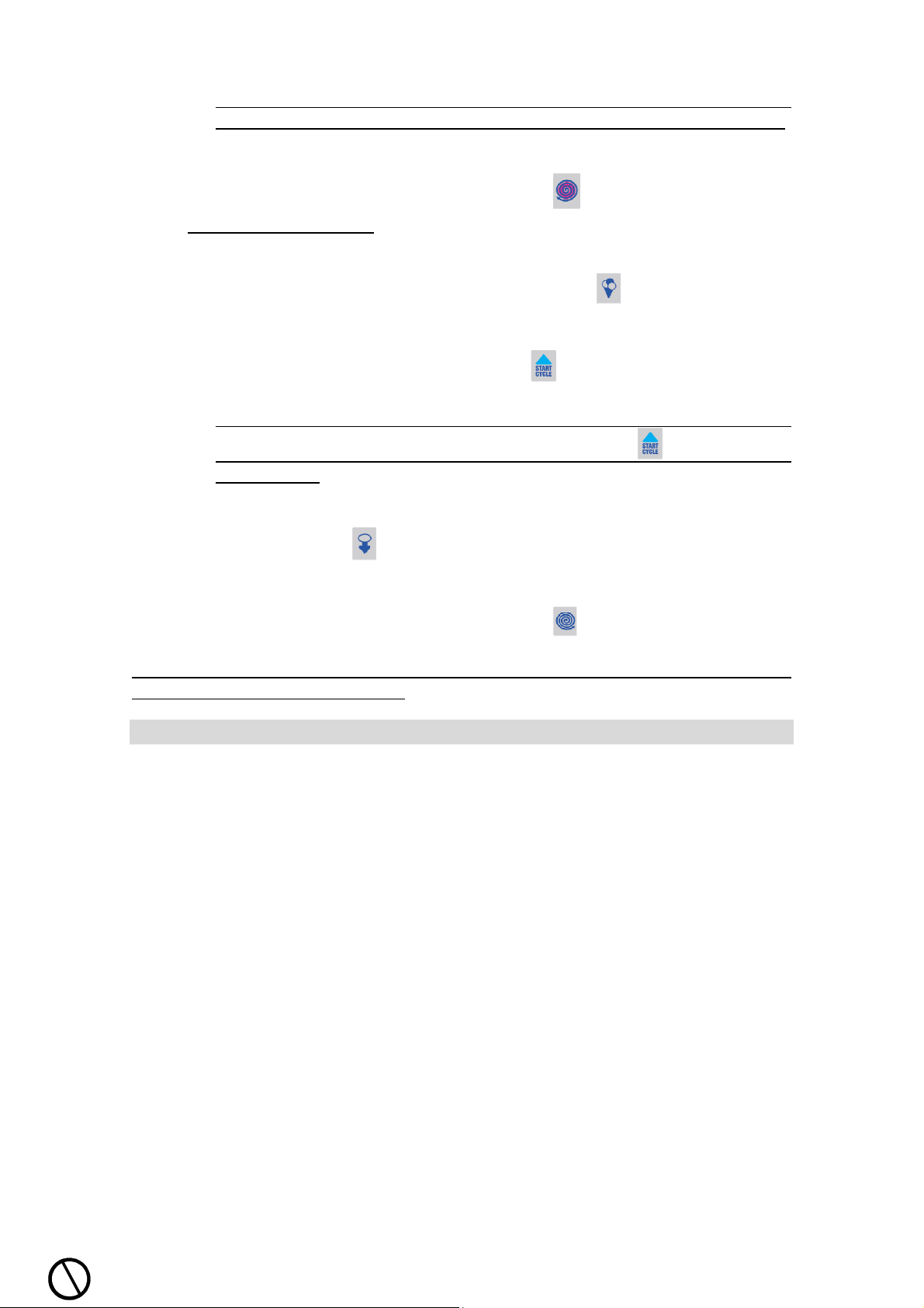
7.2.1.1 key START
7.2.1.1.1 START with the START CYCLE BUTTON on the PUSH-BUTTON PANEL
The START CYCLE button is always set to one of the menu programs
(except when first using the machine).
1. Press the button to display the set NEW
program or the LAST program used.
2. Press START CYCLE again to start the
program (NEW or LAST).
3. Program screen.
All menu programs you can started with the START CYCLE button .
The end of the cycle is notified by a beep and a light signal (if any). A message
is displayed to take out the mixture.
The machine will continue mixing the mixture without heating until extraction,
i.e. until the end of the maximum time limit.
7.2.1.1.2 START with the START CYCLE BUTTON from the MENU
1. Press the button to display the set NEW
program or the LAST program used.
49

2. Select one of the icons representing the
various menus to enter the list of available
programs.
3. Use the UP / DOWN arrows to scroll
the list of available programs.
Select the desired program by pressing the
relevant button (e.g. 29). When pressed,
the button changes color and becomes
black.
4. Press the button with the name of the
program. The button becomes black (active
button).
5. Press the button to start the machine.
The front display interacts with users giving
them instructions and information about the
processing. The end of the cycle is notified
by a beep and a light signal (if any). A
message is displayed to take out the
mixture. The machine will continue mixing
the mixture without heating until extraction,
i.e. until the end of the maximum time limit.
7.2.1.2 key COOLING in the combinate programs – from the MENU
Some programs (combined) have posibility in heating cycle to set and use the
cooling programs too.
The COOLING button activates the connection with he lower part of the
machine (batch freezer).
The function is active only when the batch freezer is on STAND BY STOP
(machine off). The button is visible only in programs combined with a cooling
system.
In all programs in which after heating phase we want to cooling down the mass
(above 0°C, except production of ice cream) the temperature of production
cylinder must be equal as temperature of ambient (not frozen). In different case
the program of cooling will not be fully implemented.
50

1. Press the button
machine to the set program (cooling).
2. Press the button to start the set
program (cooling).
7.2.1.3 key MIXING
The MIXING button activates the mixing into the kettle. The heating cycle
will be stopped automaically.
In inverter machine the set speed of the mixing is speed 5 which you can
change(+- 2 speeds).
to connect the
For increase mixer speed press button and for decrease mixer speed press
button .
1. Press the button to start a low
continuos mixing.
2. The machine starts with speed 5 for 1200
seconds.
7.2.1.4 key HALF-KETTLE HEATING
When you have less than half mixture in kettle you must press - turn on the
HALF-KETTLE HEATING button !
All scrapers which are not fully covered with mixture must be removed from the
kettle mixture.
51

The HALF-KETTLE HEATING button
activates the heating only with heater
which is positionated in the lower part of the kettle. The button can be
switched on during the heating cycle and is active only during the running
program. The function cannot be stored.
Press the button to start a half heating
(lower) of the kettle.
3. On the display show picture. If you
again press the button the picture
disappear so mean that the machine
working with both heaters.
7.2.1.5 key HEATING AT 85°C
The HEATING button is pre-set to the program ice cream mixture heating at
85°C.
1. Press the button to start pre-set
program 26.
2. The machine will start mixing and heating
the mixture up to 85°C. The front display
interacts with users giving them instructions
and information about the processing. The
end of the cycle is notified by a beep and a
light signal (if any). A message is displayed
to take out the mixture. The machine will
continue mixing the mixture without heating
until extraction, i.e. until the end of the
maximum time limit.
7.2.1.6 key STOP / RESET
The STOP button stops all active function, operation, program of the
machine indifferently in which phase the machine is. The HOME screen is
displayed.
52

7.3 PUSH-BUTTON PANEL (PRODUCTION – COOLING)
7.3.1 KEYS (cylinder – cooling part)
7.3.1.1 key START
7.3.1.1.1 START with the START CYCLE BUTTON on the PUSH-BUTTON PANEL
The START CYCLE button is always set to one of the menu programs
(except when first using the machine).
1. Press the button to display the set NEW
program or the LAST program used.
2. Press START CYCLE again to start the
program (NEW or LAST).
3. Program screen.
All menu programs are started with the START CYCLE button .
The end of the cycle is notified by a beep and a light signal (if any). A message
is displayed to take out the ice cream. Should the operator not take out the ice
cream after the notice, the machine will keep ice cream consistency
automatically until extraction, i.e. until the end of the maximum time limit.
In all DUAL machines you can with START CYCLE button set to one of the
menu programs (heating or cooling).
53

7.3.1.1.2 START with the START CYCLE BUTTON from the MENU
1. Press the button to display the set NEW
program or the LAST program used.
2. Select one of the icons representing the
various menus to enter the list of available
programs.
3. Use the UP / DOWN arrows to scroll
the list of available programs.
Select the desired program by pressing the
relevant button (e.g. 03). When pressed,
the button changes color and becomes
black.
4. Press the button with the name of the
program. The button becomes black (active
button).
5. Press the button to start the machine.
The end of the cycle is notified by a beep
and a light signal (if any). A message is
displayed to take out the ice cream. The
machine will keep ice cream consistency
automatically until extraction, i.e. until the
end of the maximum time limit.
7.3.1.2 Key CONTINUOUS MIXING
The CONTINUOUS MIXING button activated the low mixing. This low mixing
you can use for:
1. mix mixtures in the cylinder,
2. rinse the cylinder,
3. wash the cylinder at the end of production.
54

Press the
button to start a low continuos
mixing.
1. The machine starts with speed 5 for 480
seconds.
With STOP button you can stop mixing – extraction (in any phase).
7.3.1.3 Key STANDARD EXTRACTION (normal speed)
The STANDARD EXTRACTION button activated the automatic variable
speed mixing. Mixer speed will gradually increase until full ice cream extraction.
1. Press the button to start automatic
variable speed mixing.
2. The machine starts with speed 7 for 15
seconds.
3. Then machine start mixing with speed 8 for
30 seconds.
4. At last the machine start mixing with speed
8 for 3 minutes.
With STOP button you can stop mixing – extraction (in any phase).
55

7.3.1.4 Key STANDARD EXTRACTION (low speed) - from the MENU
The STANDARD EXTRACTION button activated the automatic variable
speed mixing. Mixer speed will gradually increase until full ice cream extraction.
1. In running program press the button to
start automatic variable speed mixing.
2. The machine starts with speed 5 for 10
seconds.
3. Then machine start mixing with speed 6 for
10 seconds.
4. Then machine start mixing with speed 7 for
15 seconds.
5. At last the machine start mixing with speed
8 for 200 seconds.
With STOP button you can stop extraction (in any phase).
7.3.1.5 START with the EXTRACTION FOR MAXIMUM QUANTITY OF VARIEGATED ICE
CREAM BUTTON from the MENU
56

The EXTRACTION FOR MAXIMUM QUANTITY of VARIEGATED ICE CREAM
button activated the mixing which will gradually increase until full ice cream
extraction. The program consists of 11 steps alternating mixer speed, from 6/7/8
(quick) to 2 (slow).
1. In running program press the button to
start extractionwith alternating mixing
speed.
2. The machine starts with speed 5. For
continue press START CYCLE button.
3. Now the machine works with speed 2. For
continue press START CYCLE button.
4. Now the machine works with speed 6. For
continue press START CYCLE button.
5. Now the machine works with speed 2. For
continue press START CYCLE button.
6. Now the machine works with speed 7. For
continue press START CYCLE button.
57

7. Now the machine works with speed 2. For
continue press START CYCLE
8. Now the machine works with speed 8. For
continue press START CYCLE button.
9. Now the machine works with speed 2. For
continue press START CYCLE button.
10. Now the machine works with speed 8. For
button.
continue press START CYCLE button.
11. Now the machine works with speed 2. For
continue press START CYCLE button.
12. At last the machine works with speed 8.
With STOP button you can stop mixing – extraction (in any phase).
58

7.3.1.6 START with the EXTRACTION OF CREAM AND OTHER THICK PRODUCT
BUTTON from the MENU
The EXTRACTION OF CREAM AND OTHER THICK PRODUCT button
activated a low speed extraction for creams, thick products and products
requiring low speed extraction.
1. In running program press the button to
start low mixing speed.
2. The machine starts mixing with speed 1 for
10 minutes.
In the most programs the machine offer different modes of the extraction!
So for exemple you can use these modes of extraction:
1. In running program you can use
modes.
7.3.1.7 FREEZING BUTTON from the MENU
The FREEZING button activated a cooling (compressor) for 10 seconds.
59

1. In running extraction step press the button
to start cooling.
2. The machine starts compressor for 10
seconds. On the thouch screen (cylinder –
right side) in tutor message show caption
Ur-FORCE_COMPRESSOR (switching of
the cooling for 10 seconds)…
After 10 seconds the machine
automatically switches off the compressor.
For the anticipated switches off the
compressor press again the freezing
buton.
If the FREEZENG button is grey the colling is not allowed.
With STOP button you can stop extraction (in any phase).
7.3.1.8 Key START
The ICE CREAM button activates mixing and cooling of the ice cream
mixture in the production cylinder in trough the selected program 01 - MODE1
(ICE CREAM ) pressing this key the user activates the selected program.
3. Press the button to start pre-set
program 01.
4. The machine prodiucing ice cream in
MODE 1(ice cream temperature and
density check).
During production you can change value of
MODE 1 (see chapter “PROGRAM
MODIFICATIONS AND SETTINGS”).
Production ends when set values are
reached. The end of the cycle is notified by
a beep and a light signal (if any). A
message is displayed to take out the ice
cream. The machine will keep ice cream
consistency automatically until extraction,
i.e. until the end of the maximum time limit.
60

7.3.1.9 Key STOP / RESET
The STOP button stops all active function, operation, program of the
machine indifferently in which phase the machine is.
The dual inactive HOME screen is displayed.
7.4 FIRST USING OF THE MACHINE
At the first using is necessary to select the language. If the language is not
selected machine after 30 seconds chooses English language.
1. Wait for the software to upload.
2. After Valmar screens, the LANGUAGE
SELECTION screen is automatically
displayed.
3. Select the desired language. If it is not on
the screen, press the button to enter
language selection screen 2.
4. To return to language selection screen 1
press the button
5. Press the button corresponding to the
desired language. The notice - confirm
screen is displayed.
61

6. First carefully read the text and then press
the confirm button
language chosen. The dual inactive home
screen is displayed.
7. The machine is ready for use with
instructions in the selected language.
7.5 LANGUAGE SELECTION
The machine provides instructions in the user’s language for easier use.
Language can be changed after first using the machine. In this case we will
change Italian in English language.
1. Press the left (cooking) or right (cooling) part
on the dual inactive HOME page to enter in
the single inactive home screen.
to confirm the
2. On the single inactive home screen press
the TOOLS button to enter in SETTING
menu.
3. Press the LANGUAGE button to
enter the LANGUAGE screen.
4. Press the button corresponding to the
desired language. The notice - confirm
screen is displayed.
62

5. First carefully read the text and then press
the confirm button
to confirm the
language chosen. The dual inactive home
screen is displayed.
6. The machine is ready for use with
instructions in the selected language.
7.6 DATA DOWNLOAD
7.6.1 DATA DOWNLOAD with a USB key (cooking part)
7.6.1.1 Data download for analisis – protected files (sending to VALMAR GLOBAL!)
1. Press the right part (colling) on the dual
inactive HOME screen to enter in the single
inactive home screen.
2. On the single inactive home screen press
the TOOLS button to enter in SETTING
menu.
3. Press the PARAMETERS button to
enter the PARAMETERS screen.
4. Insert the USB key into the relevant USB
port.
63

5. Press USB button
to enter in the
PASSWORD screen.
6. Enter the password - user code 333333.
7. Press the confirem or enter button
to lock the access to operation on the
machine.
8. On the message bar appears message
DOWNLOAD.
9. When the download is complete appears on
the message bar message DOWNLOAD
OK. Pull out the USB key and send data to
VALMAR GLOBAL company.
7.6.1.2 Data download of the ERRORS
1. Press the right part (colling) on the dual
inactive HOME screen to enter in the single
inactive home screen.
64

2. On the single inactive home screen press
the TOOLS button
menu.
3. Press the PARAMETERS button to
enter the PARAMETERS screen.
4. Insert the USB key into the relevant USB
port.
to enter in SETTING
5. Press ERROR button to enter in the ERROR
screen.
6. Use the UP / DOWN arrows to scroll
the errors to see the informations-details of
the selected error.
7. Press USB button to download errors
into the USB key.
65

8. On the message bar appears message
DOWNLOAD.
9. When the download is complete appears on
the message bar message DOWNLOAD
OK. Pull out the USB key.
Data from USB key (file type: xml) you can
open on computer with xml viewer (Excel,
Libre Ofice Calc, Browser, text editor...).
7.6.1.3 OPTION (surcharge) - download data of the machine, cycle (customer)
1. Press the right part (colling) on the dual
inactive HOME screen to enter in the single
inactive home screen.
2. On the single inactive home screen press
the TOOLS button to enter in SETTING
menu.
3. Press the PARAMETERS button to
enter the PARAMETERS screen.
4. Insert the USB key into the relevant USB
port.
66

5. Press “HCCP” button
to enter in
“HCCP” screen.
6. Press USB button to download “HCCP”
data into the USB key.
7. On the message bar appears message
DOWNLOAD.
8. When the download is complete appears on
the message bar message DOWNLOAD
OK. Pull out the USB key.
Data from USB key (file type: xml) you can
open on computer with xml viewer (Excel,
Libre Ofice Calc, Browser, text editor...)
7.6.2 DATA DOWNLOAD with a USB key (cooling part)
7.6.2.1 Data download for analisis – protected files (sending to VALMAR GLOBAL!)
1. Press the right part (colling) on the dual
inactive HOME screen to enter in the single
inactive home screen.
2. On the single inactive home screen press
the TOOLS button to enter in SETTING
menu.
67

3. Press the PARAMETERS button
to
enter the PARAMETERS screen.
4. Insert the USB key into the relevant USB
port.
5. Press USB button to enter in the
PASSWORD screen.
6. Enter the password - user code 333333.
7. Press the confirem or enter button
to lock the access to operation on the
machine.
8. On the message bar appears message
DOWNLOAD.
9. When the download is complete appears on
the message bar message DOWNLOAD
OK. Pull out the USB key and send data to
VALMAR GLOBAL company.
68

7.6.2.2 Data download of the ERRORS
1. Press the right part (colling) on the dual
inactive HOME screen to enter in the single
inactive home screen.
2. On the single inactive home screen press
the TOOLS button to enter in SETTING
menu.
3. Press the PARAMETERS button to
enter the PARAMETERS screen.
4. Insert the USB key into the relevant USB
port.
5. Press ERROR button to enter in the ERROR
screen.
6. Use the UP / DOWN arrows to scroll
the errors to see the informations-details of
the selected error.
69

7. Press USB button
to download errors
into the USB key.
8. On the message bar appears message
DOWNLOAD.
9. When the download is complete appears on
the message bar message DOWNLOAD
OK. Pull out the USB key.
Data from USB key (file type: xml) you can
open on computer with xml viewer (Excel,
Libre Ofice Calc, Browser, text editor...)
7.6.2.3 OPTION (surcharge) - download data of the machine, cycle (customer)
1. Press the right part (colling) on the dual
inactive HOME screen to enter in the single
inactive home screen.
2. On the single inactive home screen press
the TOOLS button to enter in SETTING
menu.
3. Press the PARAMETERS button to
enter the PARAMETERS screen.
70

4. Insert the USB key into the relevant USB
port.
5. Press “HCCP” button to enter in
“HCCP” screen.
6. Press USB button to download “HCCP”
data into the USB key.
7. On the message bar appears message
DOWNLOAD.
10. When the download is complete appears on
the message bar message DOWNLOAD
OK. Pull out the USB key.
Data from USB key (file type: xml) you can
open on computer with xml viewer (Excel,
Libre Ofice Calc, Browser, text editor...)
7.7 UPDATE OF NEW PROGRAM OR NEW DATABASE
The program is updated only when the machine is OFF!
1. Make sure the machine is OFF before starting.
This can you do if you pres red button (safety
switch). Then Insert the USB key in which you
have a new program or a new database. The
USB socket is situated in right top corner of the
back side of the machine (if you look from back
side).
2. Pull out the red button (safety switch) to switch
ON the machine.
71

3. New data is uploaded automatically. After
upload, the uploaded program and software
version and the date of the last update are
displayed. Automatic switch to the type and
model screen. The screen shows the machine
type and model. Then the notice - confirm
screen is displayed
4. Press the confirm button OK to confirm the
upload. Check if everything is updated (info
menu screen). If this message not show the
uploading does not completely concluded.
8. Then the LANGUAGE SELECTION screen is
automatically displayed. Press the button
corresponding to the desired language. The
notice - confirm screen is displayed.
5. First carefully read the text and then press the
confirm button to confirm the language
chosen. The dual inactive home screen is
displayed.
6. The machine is ready for use with instructions in
the selected language.
Press the BACK button to return to the previous screen. Press the HOME
button to cancel the operation and return to the dual inactive home screen.
7.8 WEAR OF THE SCRAPERS
When the machine reaches a certain number of hours show on display the
lower message.
Press the confirem button to progress in home screen. The message
appears at every start of the machine. Press the reset
button
to permanently delete the message.This you can do only where you changed all
the scrapers and all the sliders!
72

For all damage on the machine or to a person which derived from
inconsediration of this message the company Valmar Global is not responsible!
It is necessary to keep record on the working hours of the mixer scrapers (see
the chapter 14.5 and write hours down to appendix A)!
8 PROGRAMS
Each program consists of steps (the number of the step you can see - check in
additional active screen – chapter 7.1.1.10 or 7.1.2.11) and if the program
permitted (custom programs) you can SET in:
•
each step:
o Mixing speed (if the button racket and snail is grey the changing is not
allowed – see chapter 7.1.1.9 or 7.1.2.9);
o Mixture temperature (if the button up and down is grey the changing
is not allowed - see chapter 7.1.1.11);
o Maintenance time (if the button up and down is grey the changing is
not allowed – see chapter 7.1.1.11 or 7.1.2.10);
• all program:
o Hardnes value – only ice cream programs (if the button up and down
is grey the changing is not allowed) – see chapter 7.1.2.10.
Exemple: Program custom (pasteurize)
Program is composed from 6 steps:
• Step 1: heating of the mixture to 45°C;
• Step 2: heating of the mixture to 85°C;
• Step 3: maintenance of the mixture at 85°C;
• Step 4: cooling of the mixture to 40°C;
• Step 5: cooling of the mixture to 4°C;
• Step 6: maintenance of the mixture at 4°C.
After starting ( , , , ) the program you can change (if the program
permitted) in:
• it (only programs for producing of the ice cream) through the and
button preset value (active program parameters screen).
The changing you must confirem with button and then the new
value is valid for all cycle and saved for all the time.
• each step (other programs through the and button):
o temperature of the mixture (active program parameters screen);
o maintenance time (active program parameters screen);
and through the and button:
o mixing speed (active program parameters screen).
The changing is valid only for actual step and is autosaved for all the
time. If we want to change the one of the following step you must wait
until the machine start the desired step!
73

9 MENU PROGRAMS
9.1 MENU PROGRAMS of the HEATING PART
9.1.1 HOW ACCESS TO THE PROGRAM MENU
1. Press the left part on the dual inactive
HOME page (kettle) to enter in the single
inactive home screen.
2. On the single inactive home screen press
the TOOLS button to enter in SETTINGS
screen.
3. Press the PROGRAMS button to
enter the PROGRAM MENU.
T
ips: SHORTCUT to the program menu screen.
You can quickly enter the program menu by pressing
the START CYCLE button.
4. Select one of the available menus
represented by the relevant icons:
Ice cream menu;
Sorbet, slush, fruit sauce and
topping menu;
Chocolate ice cream, ganache,
chocolate sauce and topping menu;
Pastry products menu for custard
cream, panna cotta, Bavarian cream,
etc;
Gastronomy products menu for
salted creams, sauces, soups, etc;
…Factory program menu.
Select one of the icons representing the various
menus (e.g. ) to enter the list of available.
74

5. Use the UP / DOWN arrows
to scroll
the list of available programs.
Select the desired program by pressing the
relevant button (e.g. 26). When pressed, the
button changes color and becomes black.
6. Press the PROG i button to enter the
INFO screen with a description of the
selected program.
7. Use the UP / DOWN arrows to scroll
the description of the selected program.
Press the BACK button to return to the previous screen.
Press the HOME button to cancel the operation and return to the dual
inactive HOME screen.
9.1.2 STARTING OF THE PROGRAME
9.1.2.1 STARTING OF THE PROGRAMS with QUICK KEYS - SHORTCUT BUTTONS
For start program press desired shortcut button (e.g. ) and then press green
button-start
or double pressing on start button in push – button panel.
75

9.1.2.2 STARTING OF THE PROGRAMS with SHORTCUT START CYCLE button
You can enter the program menu by pressing the START CYCLE button .
2. When the machine is in home screen press
the button to enter the program menu.
3. Select one of the icons representing the
various menus to enter the list of available
programs.
4. Use the UP / DOWN arrows to scroll
the list of available programs.
Select the desired program by pressing the
relevant button (e.g. 34). When pressed, the
button changes color and becomes black.
5. Press the OK button to confirem - save
program.
6. Press the START CYCLE button to start
the program.
9.1.3 SETTINGS OF THE PROGRAME
9.1.3.1 QUICK KEYS (SHORTCUT BUTTON)
9.1.3.1.1 CHANGING OF THE QUICK KEY
Single inactive home screen
with factory preset
programs.
76

1. Press the left part (kettle) on the dual
inactive HOME page to enter in the single
inactive home screen.
2. On the single inactive home screen press
the TOOLS button to enter in SETTINGS
screen.
3. Press the PROGRAMS button to
enter the PROGRAM MENU.
T
ips: SHORTCUT to the program menu screen.
You can quickly enter the program menu by pressing
the START CYCLE button
4. Select one of the icons representing the
various menus to enter the list of available
programs.
5. Use the UP / DOWN arrows to scroll
the list of available programs.
Select the desired program by pressing the
relevant button (e.g. 27). When pressed, the
button changes color and becomes black.
6. After selecting the program, press the
CHANGE button to enter the following.
77

7. Press the shortcut button (e.g.
) to be
linked to the selected program.
8. Press the OK button to confirm the
changing.
Single inactive home screen
with changed preset
program - from 25 to 27.
Press the BACK button to return to the previous screen.
In this case, the changes made are not saved the shortcut button selection must
be repeated!
Press the HOME button to cancel the operation and return to the dual
inactive HOME screen .
9.1.4 SETTINGS OF THE STEP
9.1.4.1 MIXING SPEED
9.1.4.1.1 CHANGING OF THE SPEED
In actual step you can change mixer speed.
For this you can use two buttons.
If you press the button you increase the
actual speed.
If you press the button you decrease
the actual speed.
If the racket - button is grey the increasing of the speed is not allowed.
If the snail button is grey the decreasing of the speed is not allowed.
78

In the most programs the permeted changing of the speed is saved.
See the relevant program info to check whether changes are stored. If changes
are NOT stored they will be valid only for the running program!
The new parameter is valid and used during the running program and will be
valid and used when running the program in future.
9.1.4.2 DESIRED TEMPERATURE
9.1.4.2.1 CHANGING OF THE TEMPERATURE
In actual step you can change desired
temperature. For this you can use two
buttons.
If you press the UP - button you
increase the actual temperature.
If you press the DOWN - button you
decrease the actual temperature.
For confirming the new value press the SET
button.
If the UP button is grey the increasing of the temperature is not allowed.
If the DOWN button is grey the decreasing of the temperature is not allowed.
In the most programs the permeted changing of the temperature is saved.
See the relevant program info to check whether changes are stored. If changes
are NOT stored they will be valid only for the running program!
The new parameter is valid and used during the running program and will be
valid and used when running the program in future.
9.1.4.3 MAINTENANCE TIME
9.1.4.3.1 CHANGING OF THE TIME
When in actual step the desired temperature
is reach you can change maintenance time.
For this you can use two buttons.
If you press the UP - button you
increase the actual maintenance time.
If you press the DOWN - button you
decrease the actual maintenance time.
For confirming the new value press the SET
button.
If the UP button is grey the increasing of the maintenance time is not allowed.
79

If the DOWN button is grey the decreasing of the maintenance time is not
allowed.
In the most programs the permeted changing of the maintenance time is saved.
See the relevant program info to check whether changes are stored. If changes
are NOT stored they will be valid only for the running program!
The new parameter is valid and used during the running program and will be
valid and used when running the program in future.
9.2 MENU PROGRAMS of the COOLING PART
9.2.1 HOW ACCESS TO THE PROGRAM MENU:
1. Press the right part (cylinder) on the dual
inactive HOME screen to enter in the single
inactive home screen.
2. On the single inactive home screen press
the TOOLS button to enter in SETTINGS
screen.
3. Press the PROGRAMS button to
enter the PROGRAM MENU.
T
ips: SHORTCUT to the program menu screen.
You can quickly enter the program menu by pressing
the START CYCLE button
4. Select one of the available menus
represented by the relevant icons:
Ice cream menu;
Sorbet, slush, fruit sauce and
topping menu;
Chocolate ice cream, ganache,
chocolate sauce and topping menu;
Pastry products menu for custard
cream, panna cotta, Bavarian cream,
etc;
Gastronomy products menu for
salted creams, sauces, soups, etc;
…Factory program menu.
Select one of the icons representing the various
80

menus (e.g.
) to enter the list of available.
5. Use the UP / DOWN arrows to scroll
the list of available programs.
Select the desired program by pressing the
relevant button (e.g. 01). When pressed, the
button changes color and becomes black.
6. Press the PROG i button to enter the
INFO screen (6) with a description of the
selected program.
7. Use the UP / DOWN arrows to scroll
the description of the selected program.
Press the BACK button to return to the previous screen.
Press the HOME button to cancel the operation and return to the dual
inactive HOME screen.
9.2.2 STARTING OF THE PROGRAME
9.2.2.1 STARTING OF THE PROGRAMS with QUICK KEYS - SHORTCUT BUTTONS
For start program press desired shortcut button (e.g. ) and then press green
button-start
or double pressing on start button in push – button panel.
81

9.2.2.2 STARTING OF THE PROGRAMS with SHORTCUT START CYCLE button
You can enter the program menu by pressing the START CYCLE button .
1. When the machine is in dual inactive home
screen press the button to enter the
program menu.
2. Select one of the icons representing the
various menus to enter the list of available
programs.
3. Use the UP / DOWN arrows to scroll
the list of available programs.
Select the desired program by pressing the
relevant button (e.g. 16). When pressed, the
button changes color and becomes black.
4. Press the OK button to confirem - save
program. If you press the START CYCLE
button you start the selected program.
5. Press the START CYCLE button to start
the program.
9.2.3 SETTINGS OF THE PROGRAME
9.2.3.1 QUICK KEYS (SHORTCUT BUTTON)
82

9.2.3.1.1 CHANGING OF THE QUICK KEYS
Single inactive home screen
with factory preset
programs.
1. Press the right part (cylinder) on the dual
inactive HOME screen to enter in the single
inactive home screen.
2. On the single inactive home screen press
the TOOLS button to enter in SETTINGS
screen.
3. Press the PROGRAMS button to
enter the PROGRAM MENU.
T
ips: SHORTCUT to the program menu screen.
You can quickly enter the program menu by pressing
the START CYCLE button
4. Select one of the icons representing the
various menus to enter the list of available
programs.
5. Use the UP / DOWN arrows to scroll
the list of available programs.
Select the desired program by pressing the
relevant button (e.g. 03). When pressed, the
button changes color and becomes black.
83

6. After selecting the program, press the
CHANGE button
to enter the following.
7. Press the shortcut button (e.g. ) to be
linked to the selected program.
8. First carefully read the text and then press
the OK button to confirm the changing.
Single inactive menu screen
with changed preset
program - from 2 to 3.
Press the BACK button to return to the previous screen.
Press the HOME button to cancel the operation and return to the dual
inactive HOME screen.
9.2.3.2 SETTING VALUE
9.2.3.2.1 CHANGING OF THE VALUE
1. Start the selected program by pressing one
of the three available buttons.
2. In running program press SET button
84

3. Modify parameters with the buttons.
4. Press OK button to confirem the value.
If the confirm button is grey this mean
that the possibility of the changing for this
parameter is disabled.
5. Press the BACK button to return to the
previous screen.
Higher is the value more hard ice-cream arises.
9.2.4 SETTINGS OF THE STEP
9.2.4.1 MIXING SPEED
9.2.4.1.1 CHANGING OF THE SPEED
In actual step you can change mixer speed.
For this you must use the regulation button
.
If you press the button you increase the
actual speed.
If you press the button you decrease
the actual speed.
If the racket - button is grey the increasing of the speed is not allowed.
If the snail
button is grey the decreasing of the speed is not allowed.
85

In the most programs the permeted changing of the speed is saved.
See the relevant program info to check whether changes are stored. If changes
are NOT stored they will be valid only for the running program!
The new parameter is valid and used during the running program and will be
valid and used when running the program in future.
9.2.4.2 DESIRED TEMPERATURE
9.2.4.2.1 CHANGING OF THE TEMPERATURE
In actual step you can change desired
temperature. For this you can use two
buttons.
If you press the UP - button you
increase the actual temperature.
If you press the DOWN - button you
decrease the actual temperature.
For confirming the new value press the SET
button.
If the UP button is grey the increasing of the temperature is not allowed.
If the DOWN button is grey the decreasing of the temperature is not allowed.
In the most programs the permeted changing of the temperature is saved.
See the relevant program info to check whether changes are stored. If changes
are NOT stored they will be valid only for the running program!
The new parameter is valid and used during the running program and will be
valid and used when running the program in future.
9.2.4.3 MAINTENANCE TIME
9.2.4.3.1 CHANGING OF THE TIME
When in actual step the desired temperature
is reach you can change maintenance time.
For this you can use two buttons.
If you press the UP - button you
increase the actual maintenance time.
If you press the DOWN - button you
decrease the actual maintenance time.
For confirming the new value press the SET
button.
If the UP button is grey the increasing of the maintenance time is not allowed.
86

If the DOWN button is grey the decreasing of the maintenance time is not
allowed.
In the most programs the permeted changing of the maintenance time is saved.
See the relevant program info to check whether changes are stored. If changes
are NOT stored they will be valid only for the running program!
The new parameter is valid and used during the running program and will be
valid and used when running the program in future.
10 CHANGING PARAMETERS OF MACHINE
10.1 CHANGING PARAMETERS (cooking part)
10.1.1 RESET TO THE FACTORY SETTING
The user can restore all the programs, all changes are lost.
1. Press the left part on the dual inactive
HOME page (kettle) to enter in the single
inactive home screen.
2. On the single inactive home screen press
the TOOLS button to enter in SETTINGS
screen.
3. Press the RESET button to enter in the
PASSWORD screen.
87

4. Enter the password - user code 1111111.
5. Press the confirem or enter button.
6. Wait for the software to upload.
7. After Valmar screens, the LANGUAGE
SELECTION screen is automatically
displayed.
8. Select the desired language. If it is not on
the screen, press the button to enter
language selection screen 2.
9. To return to language selection screen 1
press the button
10. Press the button corresponding to the
desired language. The notice - confirm
screen is displayed.
88

11. First carefully read the text and then press
the confirm button
to confirm the
language chosen. The HOME screen is
displayed.
12. The machine is ready for use with
instructions in the selected language.
10.1.2 LOCK/UNLOCK THE ACCESS OF OPERATION
10.1.2.1 LOCK the access of operation on the machine
The user can lock access of operation on the machine.
1. Press the left part on the dual inactive
HOME page (kettle) to enter in the single
inactive home screen.
2. On the single inactive home screen press
the TOOLS button to enter in SETTINGS
screen.
3. Press the CODE button to enter in the
PASSWORD screen.
89

4. Enter the password - user code 000000.
5. Press the confirem or enter button
to lock the access to operation on the
machine.
6. On display appears the dual inactive Home
page.
10.1.2.2 UNLOCK the access of operation on the machine
10.1.2.2.1 Unlock the access of operation on the machine (until such time as the power
supply of the machine is not excluded)
The user can unlock the access of operation for period in which the power
supply to electronic is not excluded.
1. Press the left part on the dual inactive
HOME page (kettle) to enter in the single
inactive home screen.
2. On the single inactive home screen press
the LOCK button to enter in the
PASSWORD screen.
90

3. Enter the password - user code 000000.
4. Press the confirem or enter button
to unlock the access to operation on the
machine (only for time when the machine
have power source).
5. On display appears the single inactive home
screen.
10.1.2.2.2 Unlock the access of operation on the machine (permanently)
The user can permanently unlock access of operation on the machine.
1. Press the left part on the dual inactive
HOME page (kettle) to enter in the single
inactive home screen.
2. On the single inactive home screen press
the LOCK button to enter in the
PASSWORD screen.
91
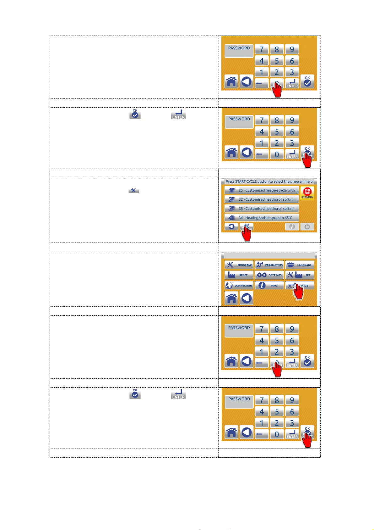
3. Enter the password - user code 000000.
4. Press the confirem or enter button
to unlock the access to operation on the
machine (only when the machine have
power source.
5. On the single inactive home screen press
the TOOLS button to enter in SETTINGS
screen.
6. Press the CODE button to enter in the
PASSWORD screen. The machine is
permanently unlocked and you can work
normally.
7. Enter the password - user code 000000.
8. Press the confirem or enter button
to lock the access to operation on the
machine.
92

9. On display appears the dual inactive Home
page.
Press the BACK button to return to the previous screen.
Press the HOME button to cancel the operation and return to the dual
inactive HOME screen.
10.2 CHANGING PARAMETERS (cooling part)
10.2.1 RESET TO THE FACTORY SETTING
The user can restore all the programs, all changes are lost.
1. Press the right part on the dual inactive
HOME page (cylinder) to enter in the single
inactive home screen.
2. On the single inactive home screen press
the TOOLS button to enter in SETTINGS
screen.
3. Press the RESET button to enter in the
PASSWORD screen.
4. Enter the password - user code 111111.
93

5. Press the confirem
or enter button.
6. Wait for the software to upload.
7. First carefully read the text and then press
the confirm button to confirm the
language chosen. The HOME screen is
displayed.
8. The machine is ready for use with
instructions in the selected language.
10.2.2 LOCK/UNLOCK THE ACCESS OF OPERATION
10.2.2.1 LOCK the access of operation on the machine
The user can lock access of operation on the machine.
1. Press the left part on the dual inactive
HOME page (kettle) to enter in the single
inactive home screen.
94

2. On the single inactive home screen press
the TOOLS button
to enter in SETTINGS
screen.
3. Press the CODE button to enter in the
PASSWORD screen.
4. Enter the password - user code 000000.
5. Press the confirem or enter button
to lock the access to operation on the
machine.
6. On display appears the dual inactive Home
page.
10.2.2.2 UNLOCK the access of operation on the machine
10.2.2.2.1 Unlock the access of operation on the machine (until such time as the power
supply of the machine is not excluded)
The user can unlock access of operations for period in which the power supply
to electronic is not excluded.
95

1. Press the left part on the dual inactive
HOME page (kettle) to enter in the single
inactive home screen.
2. On the single inactive home screen press
the LOCK button to enter in the
PASSWORD screen.
3. Enter the password - user code 000000.
4. Press the confirem or enter button
to unlock the access to operation on the
machine (only when the machine have
power source.
5. On display appears the single inactive home
screen. Now you can work normaly.
96

10.2.2.2.2 Unlock the access of operation on the machine (permanently)
The user can permanently unlock access of operation on the machine.
1. Press the left part on the dual inactive
HOME page (kettle) to enter in the single
inactive home screen.
2. On the single inactive home screen press
the LOCK button to enter in the
PASSWORD screen.
3. Enter the password - user code 000000.
4. Press the confirem or enter button
to unlock the access to operation on the
machine (only when the machine have
power source.
5. On the single inactive home screen press
the TOOLS button to enter in SETTINGS
screen.
6. Press the CODE button to enter in the
PASSWORD screen.
97

7. Enter the password - user code 000000.
8. Press the confirem or enter button
to lock the access to operation on the
machine.
10. On display appears the dual inactive Home
page. The machine is permanently
unlocked and you can work normally.
Press the BACK button to return to the previous screen.
Press the HOME button to cancel the operation and return to the dual
inactive HOME screen.
98

11 PROTECTION OF THE USER AND OF THE
MACHINE
11.1 PROTECTION OF THE USER
A safety switch, which is built into the machine under the rim of the mixture
treating cylinder, protects the operator against injuries that might be caused by
the mixer’s rotation.
Opening the mixture treating cylinder coverlid will cause the operation of the
mixer engine to shut down.
In this case, the appliance must be set to STOP position and the mixture
treating cylinder coverlid must be closed.
11.2 ELECTRICAL OVERLOAD PROTECTION
Electrical installations are protected with appropriate FUSES. If the FUSES
terminate the operation of the appliance upon its start-up, the error causing this
action must be found and corrected.
11.3 THERMIC SAFETY DEVICES
The mixer engine and the compressor engine are protected with thermal
sensors.
If temperature reaches the maximum allowed value, the protection shuts down
the engine operation. In this case, press the key STOP and allow 15 - 20
minutes for the engine to cool down. After this time, the appliance is again
ready for normal programming and operating (see the section OPERATING
THE APPLIANCE).
11.4 PROTECTION OF THE COOLING SYSTEM
The cooling system is protected with the pressostat at the maximum permited
pressure.
In the case of water shortage (water condenser machine) or dirty air condenser
(air condenser machine) the protection shuts down the operation of the cooling
compressor.
99

12 USE OF THE APPLIANCE
12.1 INSTRUCTIONS FOR THE PREVENTION OF INJURIES
Only authorized persons, who know how the machine is operated, must be
allowed to handle it. Operators must be familiar with all regulations concerning
occupational safety and fire safety measures, and they must know where fire
extinguishers are located.
Persons still in training must be constantly supervised by a designated person
in charge who knows how the machine works.
Operators must be dressed suitably (no ties, jewellers chains or belts that could
get caught in the machine) and be appropriately protected.
All warning labels on the appliance must be replaced with new ones when they
begin to fade or if they become damaged.
Before operation, the operator must make sure that the appliance is not under
maintenance, in service or in cleaning. At the end of the shift, the operator
working on the next shift or the person who will continue to operate the
appliance must be informed of the current state of the appliance.
Before every use, the operator must make sure that the floor is free of any oil
smudges or other slippery substances or objects which might cause a person to
slip or trip over.
Operators must make sure before every use of the appliance that the side
panels and the top cover of the appliance are securely fitted to the main
construction and that there are no parts or objects on the appliance or in the
cylinder that could damage the appliance during its operation.
In the event of dangerous situations (e.g. blocked mixer), which could harm the
operator’s or another person’s well being, switching off the MAIN SWITCH must
immediately shut down the appliance.
Caution must be taken because the outlet valve and the pipe are heated
because they are exposed at hot mixture. Danger of scalding!
The side panels and the top cover, as well as safety devices and protective
covers, must not be taken off during the operation of the appliance.
It is forbidden to get onto the appliance and walk upon it during its operation.
During the operation, attention must be paid to any oil leaks, increased noise,
squeaking sounds or increased vibrations. In such a case, the appliance must
be immediately shut down; a visible notice board must be placed on it with
information that it is inoperable and authorized service personnel must be
notified as soon as possible.
100
 Loading...