

Vallox Vallox 90 MV, Vallox 096 MV, Vallox TSK Multi 50 MV EH, Vallox 90K MV, Vallox TSK Multi 50 MV User Manual
...Page 1

Manual
Model
Vallox TSK Multi 50 MV
Vallox TSK Multi 50 MV EH
Vallox TSK Multi 80 MV
Vallox TSK Multi 80 MV EH
Vallox TSK Multi 80 MV EHX
Vallox 90 MV
Vallox 90K MV
Vallox 096 MV
Vallox 101 MV
Vallox 110 MV
Vallox 145 MV
Vallox 245 MV
Vallox 245 MV VKL
MANUAL
Document
D3768
Valid from
3.2.2015
Updated
9.1.2018
Ventilation units
Page 2

INTRODUCTION 4
Safety 4
Installation 4
Guarantee 4
Intended use 4
Disposal of the ventilation unit 4
Safety signs used in the instructions 5
Dierences between the models 5
Main parts 6
Vallox TSK Multi 50 MV and Vallox TSK Multi 80 MV 6
Vallox 90 MV 7
Vallox 90K MV 8
Vallox 096 MV, Vallox 110 MV, and Vallox 145 MV 9
Vallox 101 MV 10
Vallox 245 MV 11
Ventilation unit control 12
Connecting the ventilation unit to the cloud service 12
Ventilation unit control options 12
Unit software 15
Starting the unit 15
Turning the unit o 15
Starting up and shutting down the unit 15
SETUP WIZARD 16
Basic settings 16
Setup wizard 16
Select the language 16
Set the time 16
Set the 24- or 12-hour clock 16
Set the automatic daylight saving time 16
Set the date 17
Completing the setup 17
Expert settings 18
Lock code and access rights 18
User level 18
Parental controls 18
Basic fan settings 19
Adjusting the supply and extract air flows 19
Expert settings 20
Profile settings 20
At home and Away profiles 20
Boost profile 20
Fireplace profile 21
Finishing the setup 21
Four ventilation unit profiles 22
USING THE UNIT 22
At home 22
Away 22
Boost 22
Fireplace profile 22
Symbols for ventilation profiles 22
Changing the profile 23
Browsing the information of the At home, Away, and Boost
profiles. 23
Viewing the Fireplace profile information 24
Modif ying and saving the profile settings 24
Modif ying profile set tings 24
Timer functions of the Boost and Fireplace profiles 24
Viewing temperature data 25
Viewing temperature statistics 25
Relative humidity of air and carbon dioxide level statistics 26
Viewing the relative humidity of air and carbon dioxide
levels measured by the sensors 26
Filter settings 27
Setting the date the filters were last replaced 27
Setting the Filter replacement reminder interval 27
Filter maintenance reminder 28
Display settings 28
Setting the sleep time 28
Adjusting the display brightness 28
Selecting the user interface language 28
Time and date 29
Setting the time and date 29
Setting the time 29
Selecting the 24- or 12-hour clock 29
Automatic daylight saving time 29
Setting the date 30
Week clock 30
Turning the week clock on 30
Setting and editing the weekly program 31
Turning the Week clock o 31
Removing the week clock settings 31
Example of setting a weekly program 32
Turning the unit o 32
Troubleshooting 33
Condensing water (User) 33
MAINTENANCE 34
Vallox TSK Multi 50 MV ja Vallox TSK Multi 80 MV 34
Before beginning maintenance work 34
Replacing the filters (User) 34
Cleaning the heat recovery cell (User) 35
Cleaning the fans (Installer) 36
Cleaning the supply air fan 36
Cleaning the extract air fan 37
CONTENTS
NOTE
You can register your Vallox MV ventilation unit with the MyVallox Cloud cloud service and sign
in into your MyVallox Cloud account at www.myvallox.com.
INTRODUCTION
Page 3

© Vallox Oy - All rights reserved
CONTENTS
Vallox 90 MV 38
Before beginning maintenance work 38
Replacing the filters (User) 38
Cleaning the heat recovery cell (User) 39
Cleaning the fans (Installer) 40
Vallox 90K MV 41
Before beginning maintenance work 41
Replacing the filters (User) 41
Cleaning the heat recovery cell (User) 41
Cleaning the fans (Installer) 41
Cleaning the grease filter of the cooker hood (User) 41
Replacing the cooker hood lamp (User) 41
Vallox 101 MV 42
Before beginning maintenance work 42
Replacing the filters (User) 42
Cleaning the heat recovery cell (User) 43
Cleaning the fans (Installer) 44
Vallox 096 MV, Vallox 110 MV ja Vallox 145 MV 45
Before beginning maintenance work 45
Replacing the filters (User) 45
Cleaning the heat recovery cell (User) 46
Cleaning the fans (Installer) 47
Cleaning the supply air fan 47
Cleaning the extract air fan 49
Vallox 245 MV 50
Before beginning maintenance work 50
Replacing the filters (User) 50
Cleaning the heat recovery cells (User) 51
Cleaning the fans (Installer) 52
Removing and cleaning the supply and extract air fans 52
Removing the resistor 53
INSTALLATION 54
Installation site 54
Condensing water 54
Vallox TSK Multi 50 MV ja Vallox TSK Multi 80 MV 55
Installation site 55
Dimensions and duct outlets 56
Vallox 90 MV 57
Mounting on the wall 57
Mounting on the ceiling 57
Mounting the ceiling mounting plate 57
Installing the ventilation unit to the ceiling mounting plate 58
Attic floor penetration plate 58
Measuring tubes 58
Dimensioning of and space required for installation of
the Vallox Silent Klick water seal 58
Vallox 90K MV 59
Mounting on the wall 59
Installing the cooker hood 59
Measuring tubes 59
Water seal 59
Vallox 096 MV, Vallox 110 MV, Vallox 145 MV 60
Mounting on the wall 60
Mounting on the ceiling 60
Mounting the ceiling mounting plate 60
Installing the ventilation unit to the ceiling mounting plate 61
Attic floor penetration plate 61
Vallox 101 MV 62
Mounting on the ceiling 62
Mounting the ceiling mounting plate 62
Installing the ventilation unit to the ceiling mounting plate 62
Attic floor penetration plate 63
Mounting on a base ( Vallox 145 MV) 64
Measuring tubes 64
Water seal 65
Dimensioning figure and space required for installation of
the Vallox Silent Klick water seal 65
Space required by the alternative Vallox Silent Klick water seal
installation method (elbow) 65
Vallox 245 MV 66
Mounting on the floor 66
Measuring tubes 66
Installing the water seals 66
TECHNICAL DATA 67
Vallox TSK Multi 50 MV ja Vallox TSK Multi 80 MV 67
Vallox 90 MV ja Vallox 90K MV 71
Vallox 096 MV 73
Vallox 101 MV 74
Vallox 110 MV 76
Vallox 145 MV 78
Vallox 245 MV 80
Vallox 245 MV VKL 83
Internal electrical connection 84
TSK Multi 50 MV ja 80 MV 84
TSK 90 MV 85
Vallox 90K MV 86
Vallox 096 MV ja Vallox 101 MV 87
Vallox 110 MV, Vallox 145 MV, Vallox 245 MV 88
Vallox 245 MV VKL 89
External electrical connection 90
Duct radiator operation chart 91
Operation and sample connection 91
Exploded view and parts list 93
Vallox TSK Multi 50 MV ja Vallox TSK Multi 80 MV 93
Vallox 90 MV 94
Vallox 90K MV 95
Vallox 096 MV 96
Vallox 101 MV 97
Vallox 110 MV 98
Vallox 145 MV 99
Vallox 245 MV 100
User level diagrams 101
Conformity certificates 102
INTRODUCTION
Page 4
4
NOTE
For further information,
go to www.vallox.com
INTRODUCTION
SAFETY
Safe and appropriate handling requires knowledge of the basic
safety regulations, and of the intended use of the ventilation
system. Read this manual before operating the ventilation unit.
Retain the manual for later reference. If you lose the manual, it can
be downloaded from our website.
This user manual contains all the information necessary for safe
operation of the system. All persons who operate and maintain
the ventilation system must follow the instructions provided in this
manual. Furthermore, all local accident prevention regulations must
be observed.
Installation
Installation and setup should be carried out only by qualified
experts. Electrical installations and connections must be carried
out only by an electrician and in compliance with local regulations.
GUARANTEE
The guarantee and liability exclude damage resulting from:
• Inappropriate use of the ventilation system or the control unit
• Incorrect or inappropriate installation, setup or use
• Neglect of instructions concerning transportation, installation,
use, or maintenance
• Structural or electronic modifications or changes made to the
software
INTENDED USE
All Vallox ventilation units have been designed to provide
appropriate and continuous ventilation so as to present no threat to
health and to maintain structures in good condition.
IMPO RTANT
In order to ensure that the indoor air presents no harm to
health and remains optimal also for the structures of the
building, ventilation must be kept on without disruptions. It
is recommended that ventilation be left turned on during long
holidays also. This keeps the indoor air fresh and prevents humidity
from condensing in the ventilation ducts and structures. It also
reduces the risk of moisture damage.
DISPOSAL OF THE VENTILATION UNIT
Do not dispose of electronic devices with household waste. Follow
local laws and regulations on safe and ecological disposal of the
product.
WARNING
The unit is not intended for
use by children under 8 or by
persons with reduced sensory,
physical or mental capabilities,
or whose lack of knowledge
and experience do not ensure
safe operation of the unit.
Such persons can use the
unit under supervision, or by
following the instructions of
someone who is responsible for
their safety.
Page 5
5
© Vallox Oy - All rights reserved
INTRODUCTION
SAFETY SIGNS USED IN THE INSTRUCTIONS
MODELS TYPE
Vallox TSK Multi 50 M V
Vallox TSK Multi 50 M V EH
Vallox TSK Multi 80 MV
Vallox TSK Multi 80 MV EH
Vallox TSK Multi 80 MV EHX
3609-1
3609
3608-1
3608
3609-1
3608-2
(EH = post-heating)
(EHX= post-heating and additional heating)
Vallox 90 MV
Vallox 90 KMV
3527
3528
Vallox 096 MV
Vallox 101 MV
Vallox 110 MV
Vallox 145 MV
3722
3741
3702
3712
Vallox 245 MV
Vallox 245 MV VKL
3732
3732
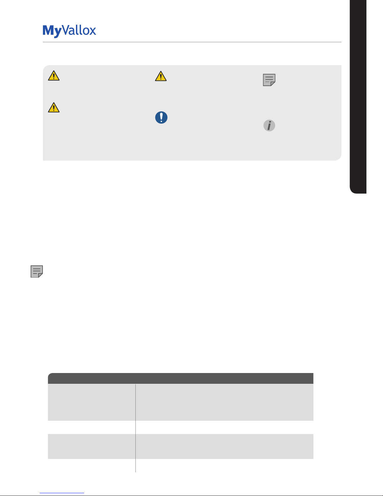
DANGER
Indicates a hazard that will result in
death or serious injury if not avoided.
WARNING
Indicates a hazard that can result in
death or serious injury if not avoided.
CAUTION
Indicates a hazard that can result
in minor or moderate injury if not
avoided.
IMPO RTANT
Indicates a hazard that can result in
damage to property or loss of data if
not avoided.
DIFFERENCES BETWEEN THE MODELS
• Power
• Size and weight
• Vallox 90 MV, Vallox 90K MV, Vallox 096 MV, and Vallox 101 do not have an additional heater. Vallox 110 MV and
Vallox 145 MV have an additional heater.
• Vallox 245 MV has an electric 1500W post-heating radiator and an electric 1500W additional heating radiator.
Vallox 245 MV VKL has a water circulation post-heating radiator and two electric 1500W additional heating
radiators.
• In Vallox 096 MV, there is a sealing tape at the bottom of the heat recovery cell. In other models, there is a
separate sealing bar under the heat recovery cell.
• Vallox 90K MV has a cooker hood underneath the unit, with a suction hole at the bottom of the unit and in the
insulation.
NOTE
The standard equipment and available accessories vary from country to country.
MOUNTING OPTIONS:
• Vallox 90 MV, Vallox 096 MV, Vallox 101 MV and Vallox 110 MV can be mounted either on the wall, or on the
ceiling by using a mounting plate (optional).
• Vallox 90K MV can only be mounted on the wall.
• Vallox 145 MV can be mounted either on the wall, or on the floor by using a floor rack (optional).
• Vallox 245 MV must always be installed on the floor by using a floor rack.
• Vallox TSK Multi 50 MV and Vallox TSK Multi 80 MV are designed to be mounted above a false ceiling.
UNIT TYPE CODES
NOTE
Indicates essential
information about the
product.
TIP
Provides additional
information about the use of
the product and its benefits.
Page 6
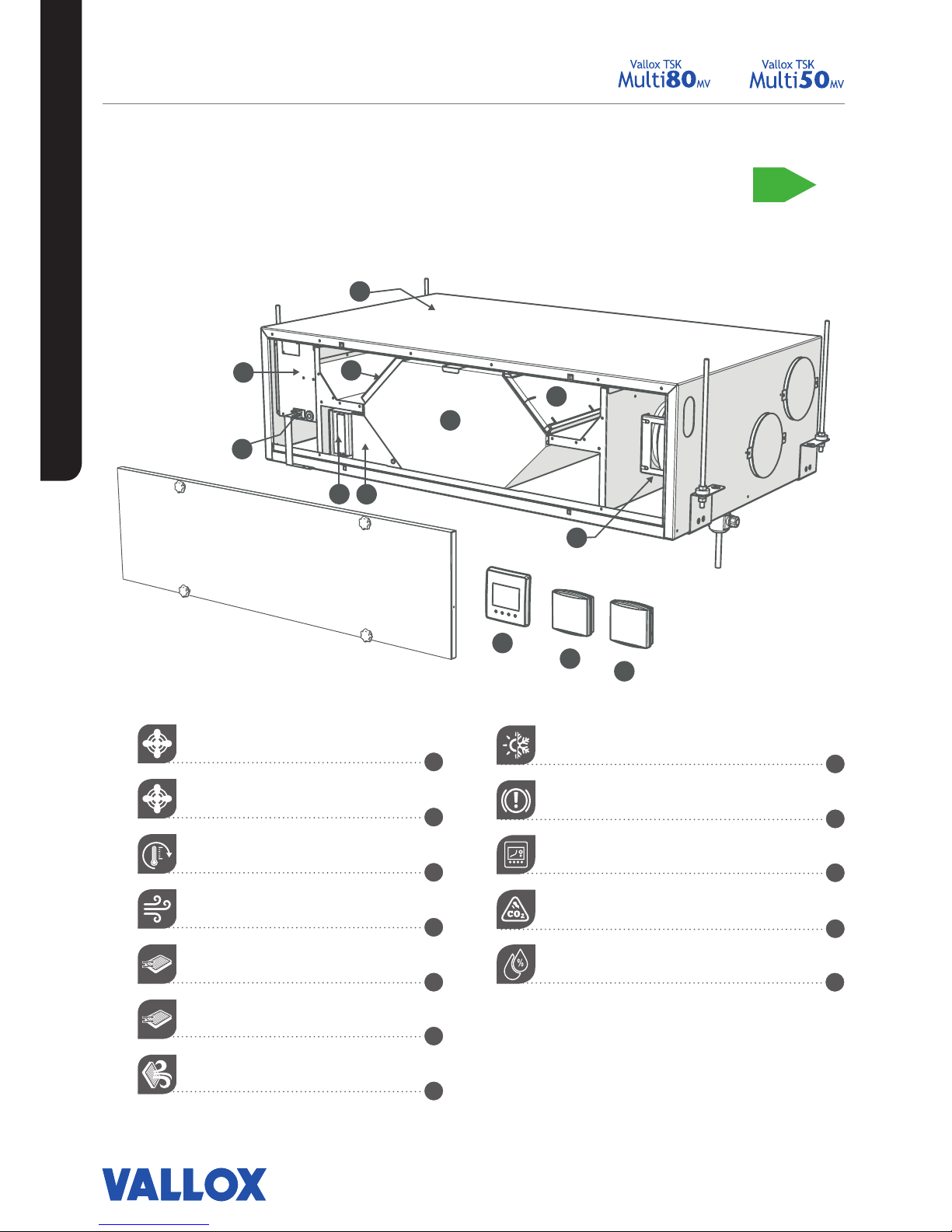
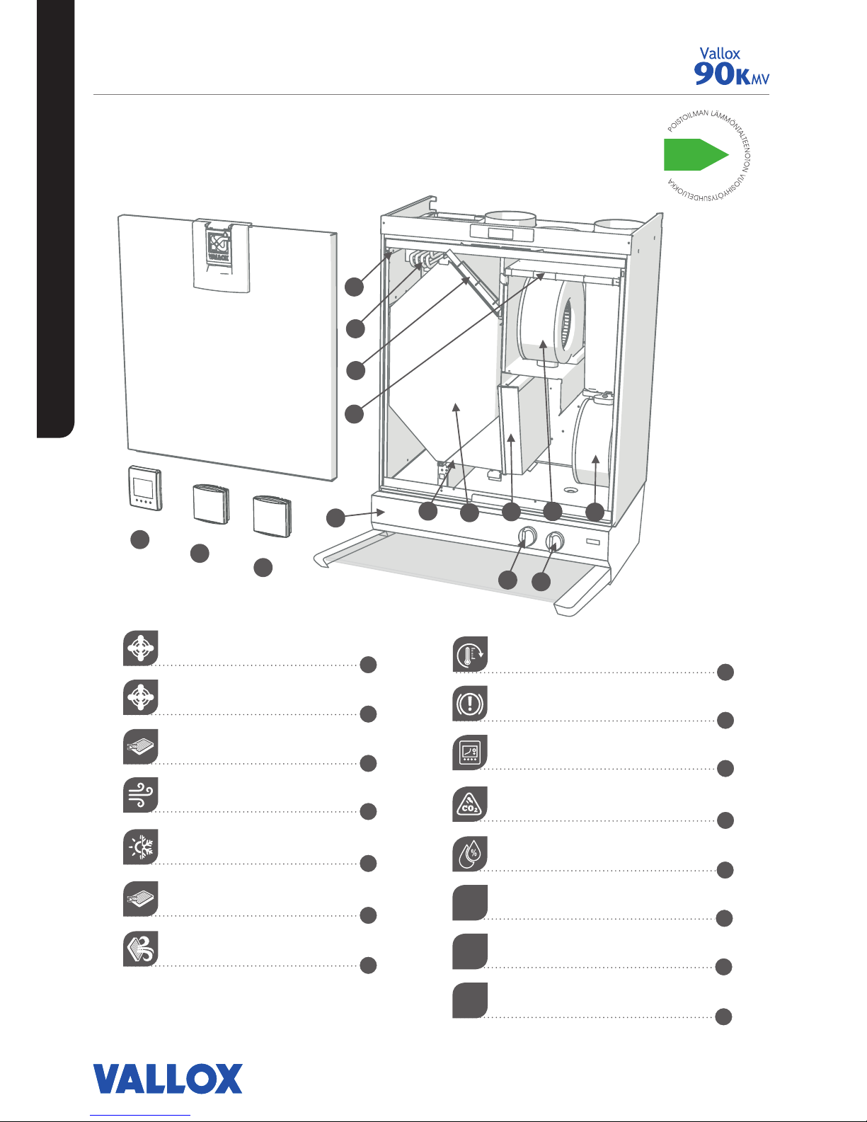
MAIN PARTS
P
O
I
S
T
O
I
L
M
A
N
L
Ä
M
M
Ö
N
T
A
L
T
E
E
N
O
T
O
N
V
U
O
S
I
H
Y
Ö
T
Y
S
U
H
D
E
L
U
O
K
K
A
A+
8
9
10
11
12
1
2
3
4
5
6
7
6
Supply air fan
Extract air fan
Post-heating radiator
Heat recovery cell
Supply air filter F7
Supply air filter G4
Extract air filter G4
R model in the figure
Bypass flap
Safety switch
Control panel
Carbon dioxide sensor
Humidity sensor
10
11
12
5
8
9
3
1
7
2
6
4
INTRODUCTION
VALLOX TSK MULTI 50 MV AND
VALLOX TSK MULTI 80 MV
Page 7
7
© Vallox Oy - All rights reserved
5
10
11
12
8
9
3 1
7
2
6
4
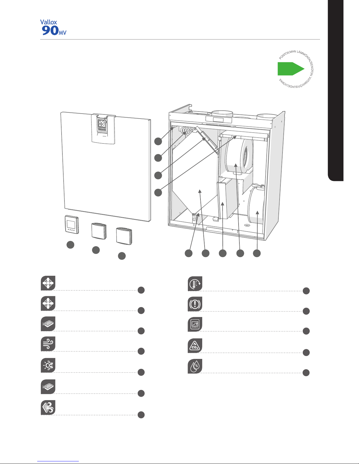
Extract air fan
Supply air fan
Supply air filter F7
Heat recovery cell
Automatic summer/winter damper
Supply air filter G4
Extract air filter G4
Post-heating radiator
Safety switch
Control panel
Carbon dioxide sensor
Humidity sensor
B
8
9
10
11
12
1
2
3
4
5
6
7
R model in the
figure
MAIN PARTS
INTRODUCTION
VALLOX 90 MV
Page 8
8
INTRODUCTION
VALLOX 90K MV
Extract air fan
Supply air fan
Supply air filter F7
Heat recovery cell
Automatic summer/winter damper
Supply air filter G4
Extract air filter G4
Post-heating radiator
Safety switch
Control panel
Carbon dioxide sensor
Humidity sensor
Cooker hood
Cooker hood damper adjustment
Fan speed adjustment
B
MAIN PARTS
5
10
11
12
8
9
3 1
7
2
6
4
13
14
15
8
9
10
11
12
1
2
3
4
5
6
7
13
14
15
R model in the
figure
Page 9
9
© Vallox Oy - All rights reserved
9
© Vallox Oy - All rights reserved
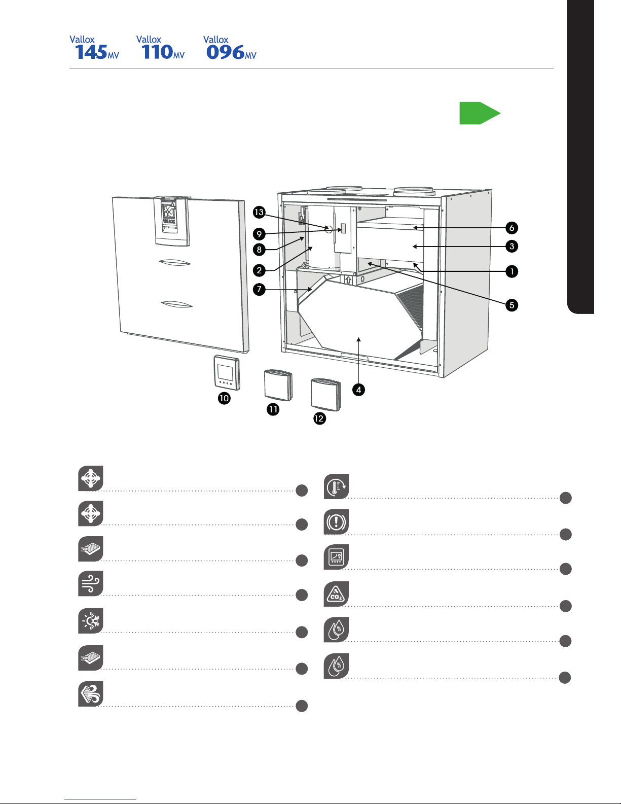
VALLOX 096 MV, VALLOX 110 MV, AND VALLOX 145
MV
R model in the
figure
Extract air fan (behind the protective cover)
Supply air fan (behind the extract air duct)
Supply air filter F7
Heat recovery cell
Bypass flap
Supply air filter G4
Extract air filter G4
P
O
I
S
T
O
I
L
M
A
N
L
Ä
M
M
Ö
N
T
A
L
T
E
E
N
O
T
O
N
V
U
O
S
I
H
Y
Ö
T
Y
S
U
H
D
E
L
U
O
K
K
A
A+
MAIN PARTS
INTRODUCTION
Post-heating radiator (behind the extract air duct)
Safety switch
Control panel
Carbon dioxide sensor
Humidity sensor
Internal humidity sensor
8
9
10
11
12
1
2
3
4
5
6
7
13
Page 10
10
INTRODUCTION
1
5
3
6
8
9
13
7
2
4
12
11
10
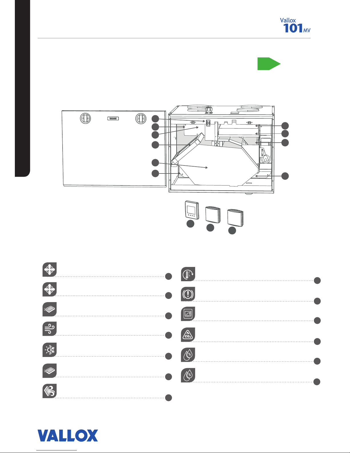
VALLOX 101 MV
R model in the
figure
Extract air fan
Supply air fan
Supply air filter F7
Heat recovery cell
Bypass flap
Supply air filter G4
Extract air filter G4
P
O
I
S
T
O
I
L
M
A
N
L
Ä
M
M
Ö
N
T
A
L
T
E
E
N
O
T
O
N
V
U
O
S
I
H
Y
Ö
T
Y
S
U
H
D
E
L
U
O
K
K
A
A+
MAIN PARTS
Post-heating radiator (in the supply air duct)
Safety switch
Control panel
Carbon dioxide sensor
Humidity sensor
Internal humidity sensor
8
9
10
11
12
1
2
3
4
5
6
7
13
Page 11
11
© Vallox Oy - All rights reserved
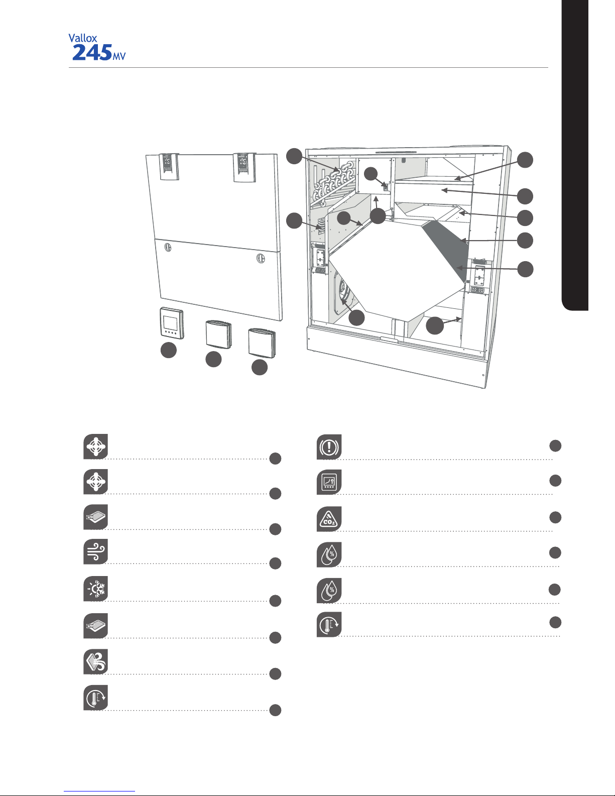
INTRODUCTION
R model in the
figure
Supply air fan
Extract air fan
Supply air filter F7
Heat recovery cell, 2 pcs
Bypass flap
Supply air filter G4
Extract air filter G4
Post-heating radiator
5
1
4
8
7
9
4
3
5
14
1
4
8
7
9
4
3
2
6
13
10
11
12
Safety switch
Control panel
Carbon dioxide sensor
Humidity sensor
Internal humidity sensor (behind the electric box)
Post-heating liquid radiator
8
9
10
11
12
1
2
3
4
5
6
7
13
14
VALLOX 245 MV
Page 12

12
INTRODUCTION
TIP
The MyVallox Control control
panel automatically switches to
the sleep mode when the Sleep
time set in the Display settings
has elapsed. You can wake up
the control panel by pressing
any control panel button.
VENTILATION UNIT CONTROL
Connecting the ventilation unit to the
cloud service
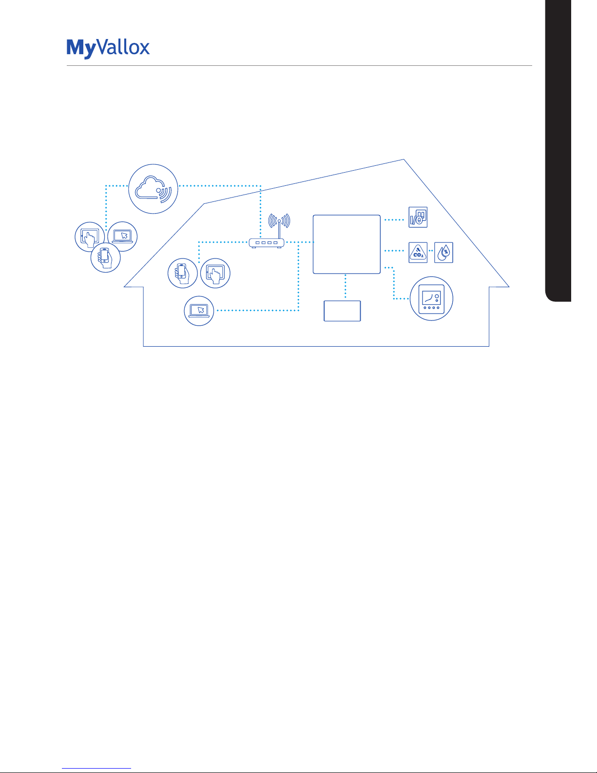
The ventilation unit can be connected to the MyVallox
Cloud cloud service. The cloud service allows for controlling
ventilation remotely also, using e.g. a smartphone or tablet.
Also the unit software is updated automatically through
the cloud service. To connect to the cloud service, the
ventilation unit must be connected to the Internet via LAN
and registered with the cloud service. At the same time you
create a MyVallox Cloud account for yourself. Read more
about the service at www.myvallox.com.
Ventilation unit control options
Operation of the Vallox ventilation unit can be controlled by
the following means:
• Through the control panel installed in the building
• Through the MyVallox Home local area network
connection and the MyVallox Home/Cloud user interface.
• Through the MyVallox Cloud cloud service and the
MyVallox Home/Cloud user interface.
• Through a remote monitoring service or building
automation that uses voltage signals or Modbus
messages
In addition to the integrated humidity sensor, ventilation
can also be adjusted automatically using the optional
carbon dioxide and humidity sensors. When these are
used, ventilation remains optimal even when the dwelling is
unoccupied.
Each user can use the week clock to adjust the ventilation to
fit their individual lifestyle.
Page 13
13
© Vallox Oy - All rights reserved
INTRODUCTION
SYSTEM DESCRIPTION
Modbus
1
4
2
3
5
6
MyVallox Cloud
Vallox MV
MyVallox Control
1. Internet
2. WLAN
3. Router
4. WLAN/LAN
5. Additional switch
6. Sensors
VENTILATION UNIT CONTROL
Page 14
14
VENTILATION UNIT CONTROL
The Change profile button changes the ventilation profile or
the operating status used.
The Profile information button allows you to view the
currently active profile information.
The Temperature button displays temperature and sensor
information.
The Settings button opens the settings.
The Back button takes you backwards in the menu.
The Left arrow button takes you leftward in the menu.
The Right arrow button takes you rightward in the menu.
The OK button accepts the selected option.
The Select button selects an option from the list.
The Edit button allows you to edit settings.
The Plus button allows you to:
• Increase the value of the selected setting.
• Move to the next menu item.
• Move from a one-day view to a week view in the
temperature, relative humidity of air and carbon dioxide
level graphs.
The Minus button allows you to:
• Reduce the value of the selected setting.
• Return to the previous menu item.
• Move from a week view to a one-day view in the
temperature, relative humidity of air and carbon dioxide
level graphs.
The Up arrow button takes you upward in the menu.
The Down arrow button takes you downwards in the menu.
The Statistics button opens the temperature, relative
humidity of air and carbon dioxide level graphs (1 day or 1
week).
These icons indicate the hierarchy level of the settings.
This icon indicates when the feature is turned o at your user
level.
BUTTON DESCRIPTION
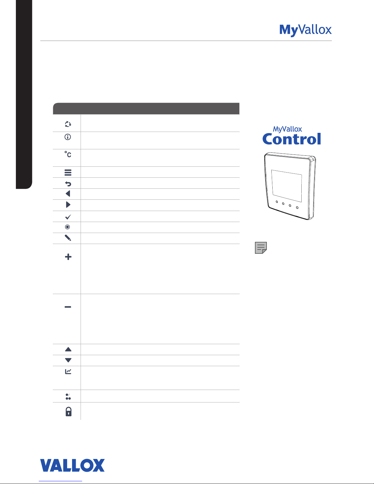
NOTE
The MyVallox Control control
panel contains the buttons
described in the following table.
You can press the graphical user
interface buttons by using the
ring-shaped buttons below the
control panel. The control panel
does not have a touch screen.
CONTROL PANEL BUTTONS
INTRODUCTION
Page 15

15
© Vallox Oy - All rights reserved
INTRODUCTION
STARTING UP AND SHUTTING DOWN THE UNIT
Unit software
We recommend that the latest software version be always
used. Check and download the latest version at
http://www.vallox.com or at cloud.vallox.com either before or
immediately after startup.
The current software version of the ventilation unit is shown
on the control panel display when the unit is connected to
the mains or factory settings are restored. Alternatively, the
current software version can be checked from the Diagnostics
display of the Maintenance menu.
Download the software into the unit using the USB Micro-B
port of the control panel.
Starting the unit
If you are starting the ventilation unit for the first time or after
a maintenance procedure, first connect it to the mains. This
will start the unit. During start-up, the diagnostics display
appears for a few seconds. Once the download is complete,
a profile display opens showing the latest saved status of the
unit.
If the ventilation unit was turned o from the control panel
(see Turning the unit o), you can start it by pressing any
control panel button.
Turning the unit o
To turn the ventilation unit o:
1. Select Turn unit o using the arrow buttons.
2. Select OK.
3. Press OK to confirm the selection. The ventilation unit
has now been turned off.
IMPORTANT
It is recommended that the ventilation be kept turned on
without disruptions.
NOTE
The first starting of the unit may
take a while, because of the
software version check.
Page 16
16
SETUP WIZARD
BASIC SETTINGS
SETUP WIZARD
SETUP WIZARD
The following settings will be configured during the setup of the
ventilation system:
• user interface language
• time and date
• system administrator lock code
• parental controls, if turned on
• fan settings
• user profile settings, such as the temperature.
The qualified ventilation installer must complete the fan settings in
accordance with the ventilation plan. Do not change these settings.
1. Start the Vallox ventilation unit.
2. When the unit is started for the first time, the language menu
opens on the control panel display. Select OK.
3. The setup wizard is launched.
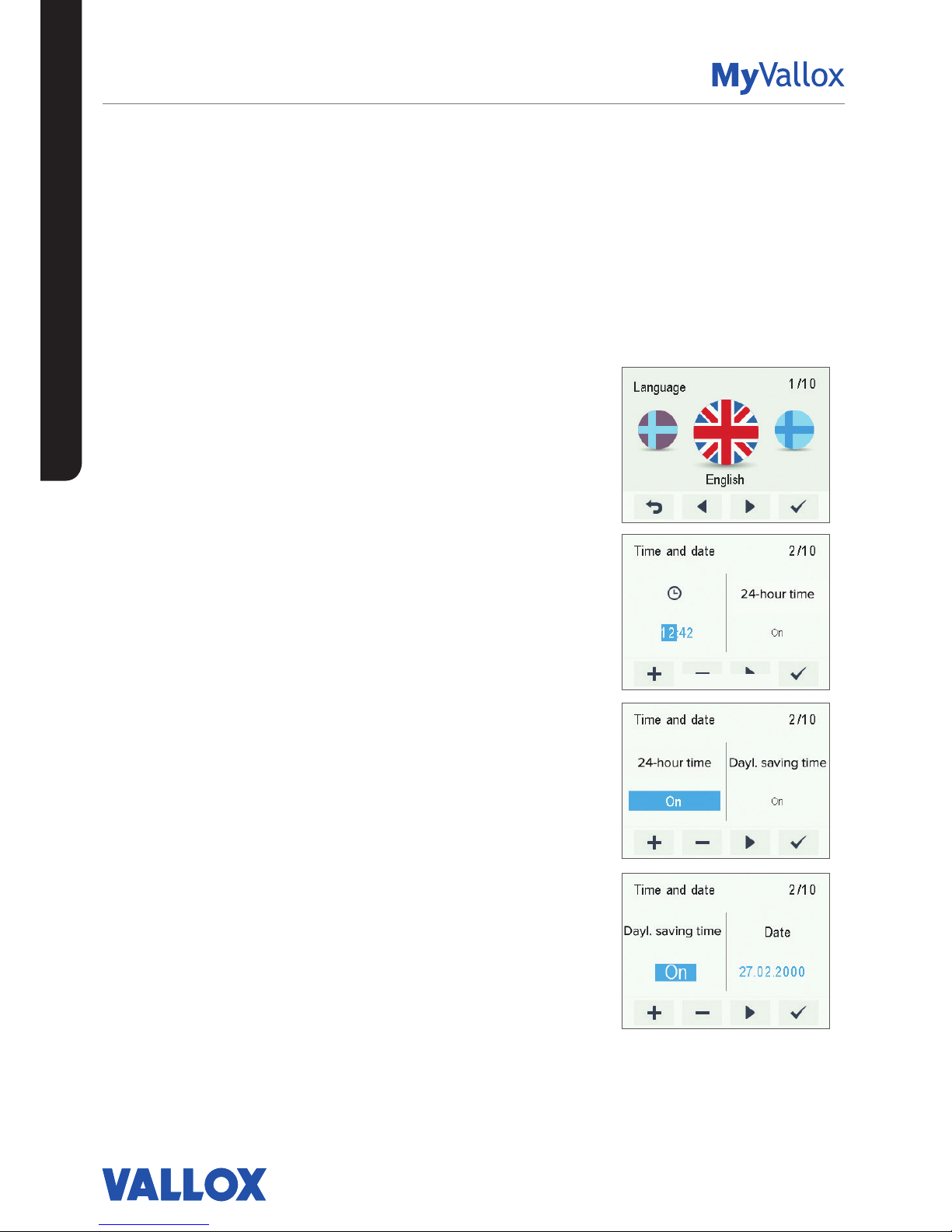
Select the language
1. Use the arrow buttons to select the language.
2. Select OK.
3. The language has now been set, and the control panel will
move on to the time settings.
Set the time
1. Use the Plus and Minus buttons to set the hours.
2. Select Right arrow.
3. Use the Plus and Minus buttons to set the minutes.
4. The time is now set.
5. Proceed to the next phase by selecting Right arrow.
Set the 24- or 12-hour clock
The 24-hour clock is used by default.
To use the 12-hour clock:
1. Select Minus. The 24-Hour time setting value is changed to O.
2. Proceed to the next phase by selecting Right arrow.
Set the automatic daylight saving time
By default, the automatic daylight saving time is on.
To use the manual daylight saving time setting:
1. Select Minus. The Dayl.saving time setting value is changed to O.
2. The manual daylight saving time setting is now on.
3. Proceed to the next phase by selecting Right arrow.
Page 17
17
© Vallox Oy - All rights reserved
SETUP WIZARD
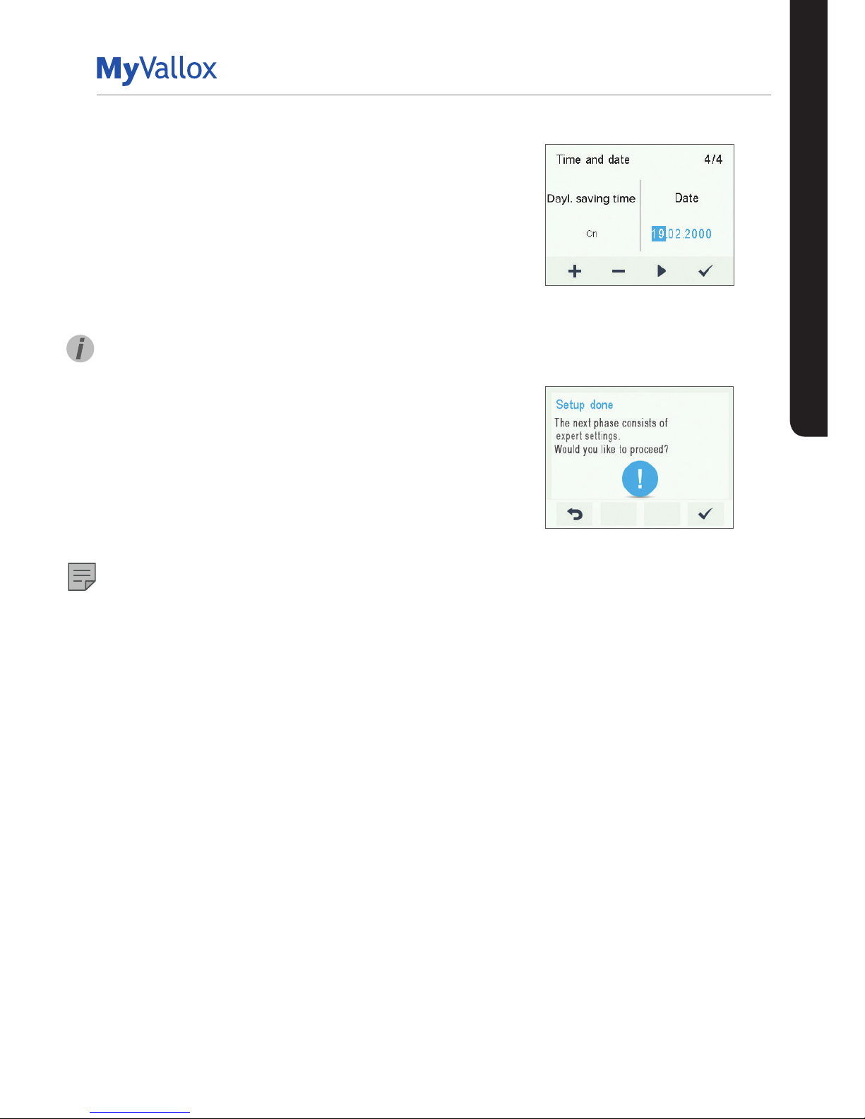
Set the date
1. Use the Plus and Minus buttons to set the date.
2. Select Right arrow.
3. Use the Plus and Minus buttons to set the month.
4. Select Right arrow.
5. Use the Plus and Minus buttons to set the year.
6. Select OK.
7. The date is now set.
TIP
You can browse the Time and date settings by using the
Right arrow button.
Completing the setup
Once you have completed the basic settings for the setup,
select OK to proceed to the expert settings of the ventilation
unit.
Select Back to use the ventilation unit on factory settings
and complete the configuration of the expert settings later.
NOTE
Expert settings are settings that use e.g. airflow
measurement equipment.
BASIC SETTINGS
Page 18

18
EXPERT SETTINGS
Lock code and access rights
NOTE
The default lock code is 0000, i.e. the lock code inquiry is
turned o.
1. Enter the first digit of the lock code using the Up arrow and
Down arrow buttons. Proceed to the next digit by selecting
Right arrow.
2. Set the remaining digits of the lock code in the same way.
3. Select OK.
4. The lock code is now set.
User level
There are three user levels:
• Extensive - At the extensive user level, users can access all
ventilation unit settings.
• Normal - At the normal user level, access to some menus is
restricted.
• Limited - At the limited user level, users have access only to
the basic functions of the ventilation unit.
For more information on user levels, see Chapter “User level
diagrams”.
1. Use the Plus and Minus buttons to set the user level.
2. The user level is now set.
3. Proceed to the next phase by selecting Right arrow.
Parental controls
Parental controls lock the control panel so that no damage
can be done to the ventilation unit by random pressing of the
control panel buttons.
1. By default, the parental controls are turned off. Use the Plus
and Minus buttons to turn the parental controls on.
2. Select OK.
3. The parental controls are now set.
TIP
You can browse the Lock code and access rights settings with
the Right arrow button.
NOTE
The access code of the parental controls cannot be changed.
The access code is always 1001.
Parental controls access code:
1 0 0 1
Enter the new access code
here:
SETUP WIZARD
Page 19
19
© Vallox Oy - All rights reserved
SETUP WIZARD
EXPERT SETTINGS
Basic fan settings
IMPORTANT
Adjust the air flows according to the values specified in the
ventilation plan. It is recommended that the air flows be
adjusted without having to choke the air flows at the valves.
This is the most energy-ecient set up.
First, set both values as close to the ideal value as possible
by looking at the supply and extract air fan curves. If the
ratio between the air flows is very high at first, the ventilation
unit may have to carry out extra defrosting cycles in sub-zero
temperatures, thus making adjustment of the air flows more
complicated. Check the air flows by measuring them at the
valves, and fine-tune the percentage values as required.
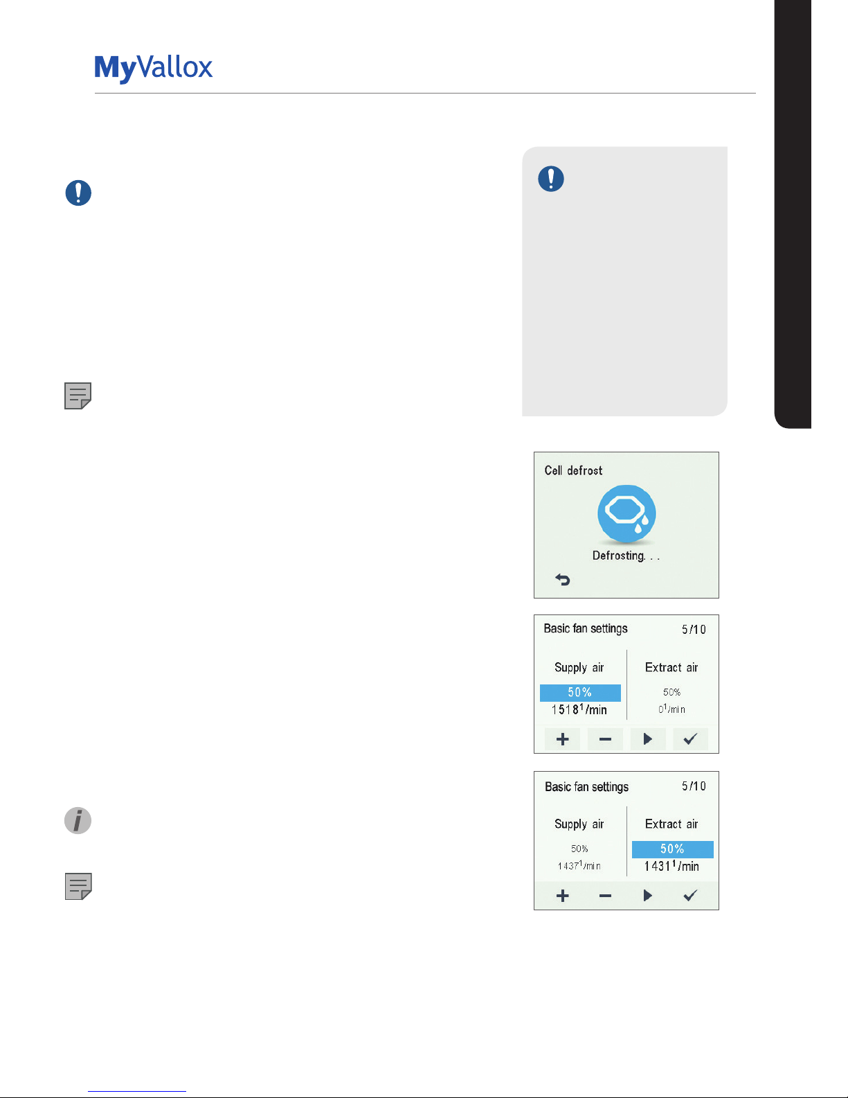
NOTE
If the outside air is extremely cold (below -10°C on an
aluminium cell or below -3°C on a plastic cell), the ventilation
unit may have to defrost the heat recovery cell. If this
happens, the Defrosting icon will be displayed on the control
panel. The air flows cannot be adjusted during defrosting.
Adjusting the supply and extract air flows
1. Use the Plus and Minus buttons to set the supply air fan
ratio as a percentage of the maximum output ratio. The
fan speed (1/min) will change accordingly.
2. Measure and adjust the supply air flows from the valves.
3. Press the Right arrow button.
4. Use the Plus and Minus buttons to set the extract air fan
ratio as a percentage of the maximum output ratio. The
fan speed (1/min) will change accordingly. Measure and
adjust the extract air flows from the valves.
5. Select OK. Supply and extract air flow settings are now
complete.
6. Record the set percentages in the measurement log.
Do not change the output ratio between the supply and
extract air fans once the settings are complete. The same
ratio is also used in the Away and Boost profiles.
TIP
You can browse the Basic fan settings by using the Right
arrow button.
NOTE
If the use of the ventilation unit has been started before air
flow adjustment, we recommend that the factory settings of
the ventilation unit be restored before adjustment is started
(see “Save and restore settings”). This ensure that the unit
settings are optimal for adjusting the air flows and that any
settings made during the adjustment are saved as setup
settings. Any later changes will be saved as user settings.
Both the setup and user settings can be restored later even
if the settings had been modified later.
IMPORTANT
The supply and extract air
settings have been completed
by a specialist during setup
of the ventilation unit. These
settings should be changed
only when the ventilation
unit is reconfigured, and not
at any other time. Changing
the ventilation settings so
that overpressure is created
can result in damage to the
structures of the building.
Page 20
20
SETUP WIZARD
PROFILE SETTINGS
NOTE
By default, the At home profile uses the higher basic ventilation
fan speed. We recommend that this basic ventilation setting be
used with the At home profile. Once you have set the fan speed
for the At home profile, the fan speed for the Away profile will
by default be set to -30% of the At home profile fan speed.
We recommend that the default fan speed settings be used.
However, the settings can be changed as required.
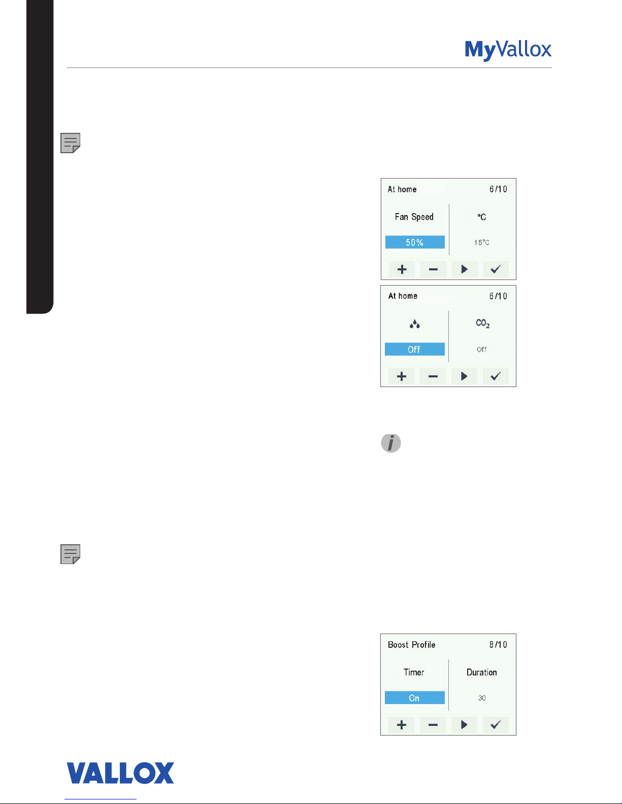
At home and Away profiles
To set the ventilation settings of the profiles:
1. Use the Plus or Minus buttons to set the profile fan speed
as a percentage of the maximum output ratio.
2. The fan speed is now set for the profile.
3. Proceed to the next phase by selecting Right arrow.
4. Use the Plus or Minus buttons to set the desired supply air
temperature for the profile. You can adjust the temperature
in the range +10°C ... +25°C.
5. The profile supply air temperature is now set.
6. Proceed to the next phase by selecting Right arrow.
7. Use the Plus and Minus buttons to turn the automatic fan
speed control based on relative humidity of air on or off.
8. The automatic fan speed control, based on the relative
humidity of air, is now set.
9. Proceed to the next phase by selecting Right arrow.
10. Use the Plus and Minus buttons to turn the automatic fan
speed control based on carbon dioxide content on or off.
11. The automatic fan speed control, based on the carbon
dioxide level, is now set.
12. Select OK.
13. Proceed to the settings of the next profile by selecting Right
arrow.
NOTE
Once you have set the fan speed for the At home profile, the
fan speed for the Boost profile will by default be set to +30%
of the At home profile fan speed. It is recommended that this
fan speed setting be used for the Boost profile. However, the
setting can be changed as required.
Boost profile
The fan speed, supply air temperature, and the automatic fan
speed control (based on either relative humidity of air or carbon
dioxide level) is set for the Boost profile in the same way as for
the At home and Away profiles. The Boost profile also has a
timer setting.
TIP
You can browse the At home
profile settings with the Right
arrow button.
EXPERT SETTINGS
Page 21
21
© Vallox Oy - All rights reserved
SETUP WIZARD
EXPERT SETTINGS
1. Use the Plus and Minus buttons to turn the profile timer
function on or off. The options are:
• On — When the timer is on, the Boost profile is used only for the
period specified in the timer.
• O — When the timer is off, the Boost profile is used until the
profile is changed, either manually or automatically by the week
clock.
2. Proceed to the next phase by selecting Right arrow.
3. Use the Plus and Minus buttons to set the profile timer duration
in minutes.
4. Select OK.
5. Proceed to the settings of the next profile by selecting Right
arrow.
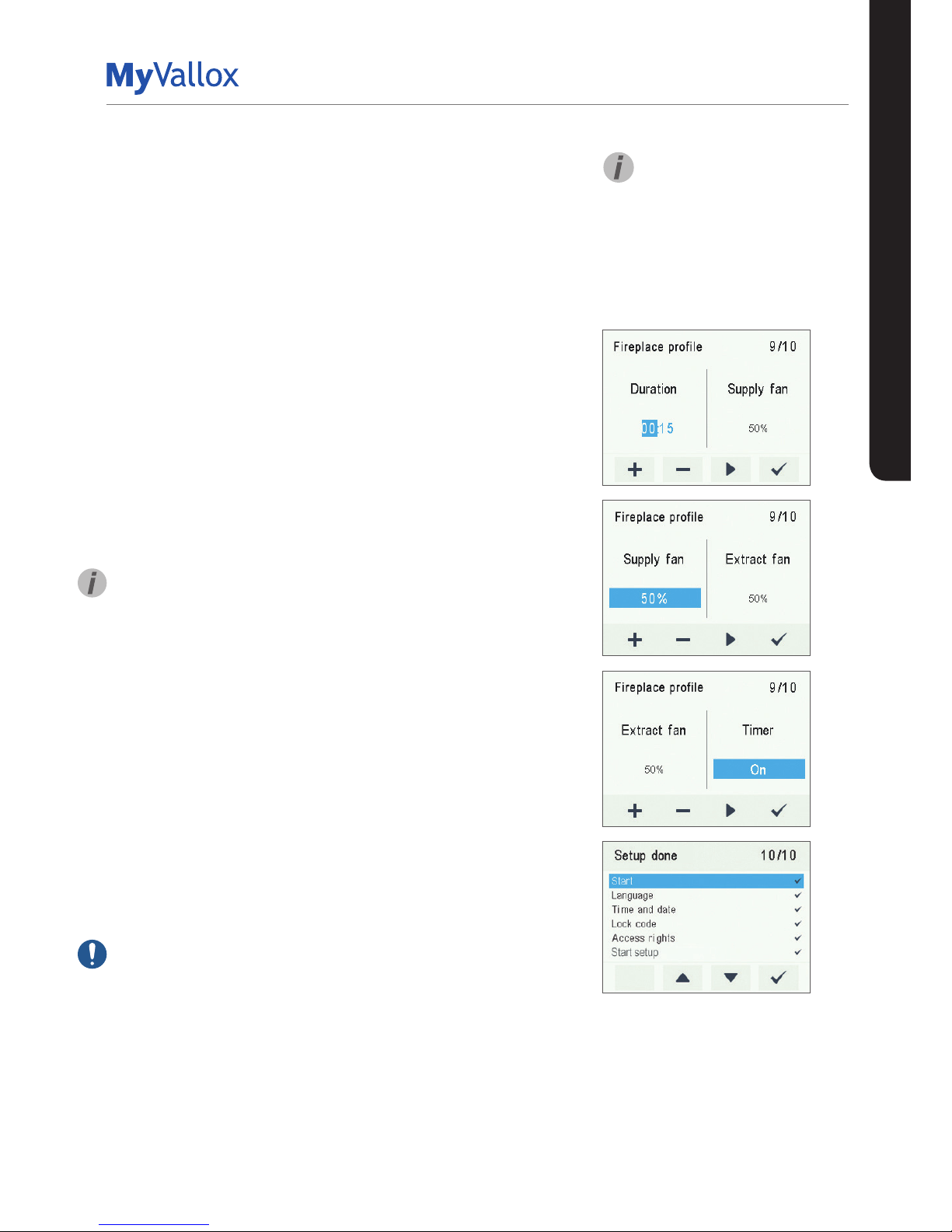
Fireplace profile
1. Use the Plus and Minus buttons to set the Fireplace profile
timer duration in minutes.
2. The Fireplace profile timer duration is now set.
3. Proceed to the next phase by selecting Right arrow.
4. Use the Plus and Minus buttons to set the Fireplace profile’s
supply air fan speed as a percentage of the maximum output
ratio.
TIP
It is recommended that a higher supply air fan speed be used in
the fireplace profile to create overpressure in the ventilation zone.
Reducing the extract air fan speed is not recommended.
5. The supply air fan speed of the Fireplace profile is now set.
6. Proceed to the next phase by selecting Right arrow.
7. Use the Plus and Minus buttons to set the extract air fan speed
of the Fireplace profile as a percentage of the maximum output
ratio.
8. The extract air fan speed of the Fireplace profile is now set.
9. Proceed to the next phase by selecting Right arrow.
10. Use the Plus and Minus buttons to turn the profile timer
function on or off. The options are:
• On — When the timer is on, the Fireplace profile is used only for the
period specified by the timer.
• O — When the timer is off, the Fireplace profile is used until the
profile is changed, either manually or automatically by the Week
clock.
11. The profile timer function is now set.
12. Select OK.
IMPORTANT
Do not turn the timer function o if there is no timer in the external
fireplace switch.
Finishing the setup
Once you have completed all phases of the setup, finish up the
setup as follows:
1. To change any of the set values, use the arrow buttons to
return to the desired line and then press OK.
2. When you are satisfied with the settings, use the arrow buttons
to select Start and then press OK.
TIP
You can browse the settings
of the Boost or the Fireplace
profile by using the Right arrow
button.
Page 22
22
USING THE UNIT
FOUR VENTILATION UNIT PROFILES
At home
Use this ventilation profile when the dwelling or the premises
are occupied.
Away
Use this ventilation profile when the dwelling or premises are
unoccupied, e.g. during a trip or other long absence.
Fireplace profile
Use this ventilation profile when, for example, you are making
a fire in the fireplace. This profile is primarily used to create
momentary overpressure in the apartment.
Boost
Use this profile to increase the ventilation rate, e.g. when there
are more people than usual in the dwelling or elsewhere on the
premises.
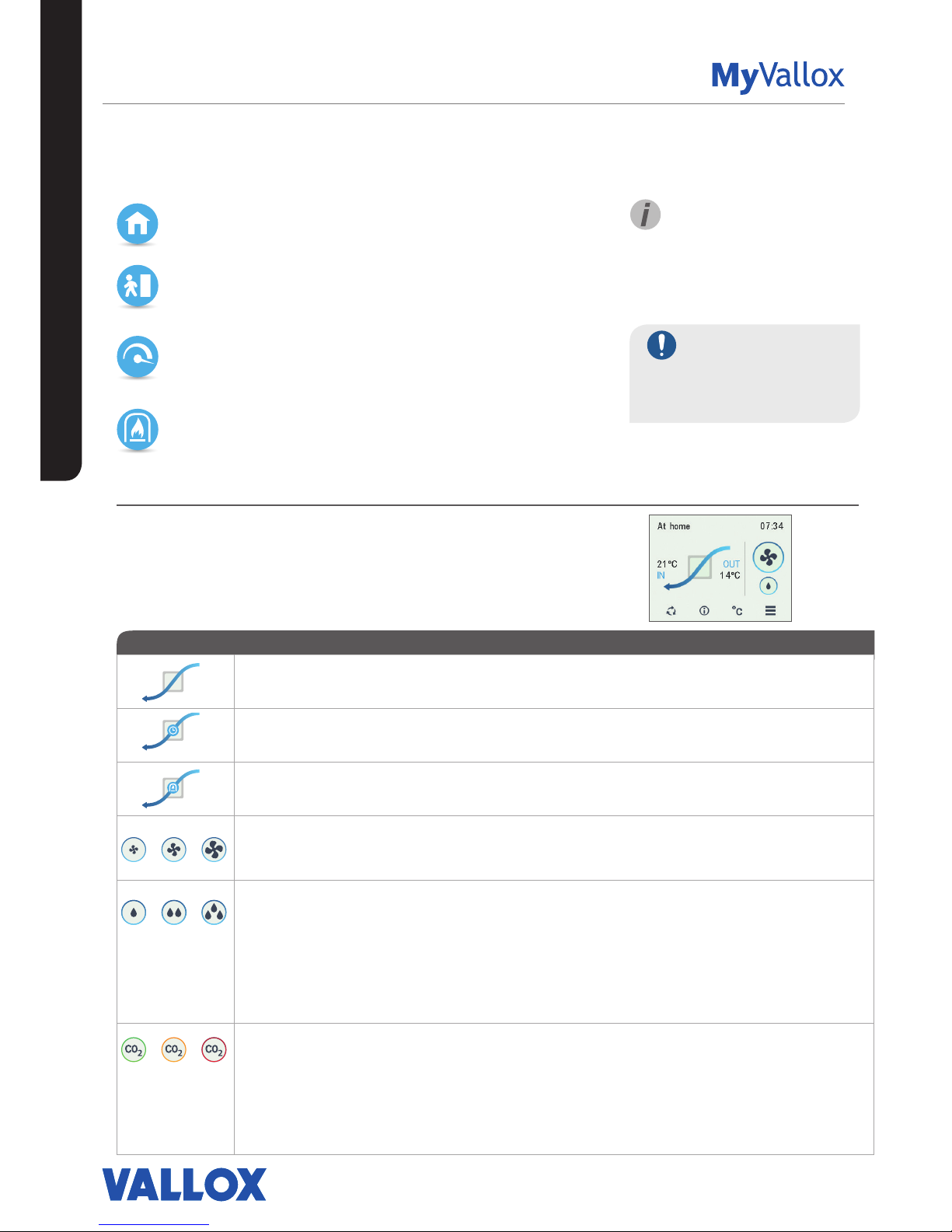
Symbols for ventilation profiles
The following symbols are used on the main displays of the profiles:
Table 2. Profile symbols
SYMBOL DESCRIPTION
The profile in use is either the At home, Away, or Boost profile. The week clock is turned o.
The profile in use is either the At home, Away, or Boost profile. The week clock is on.
The Fireplace profile is used. The week clock might be turned on.
These symbols indicate the currently active profile. The smallest fan icon indicates that the Away
profile is in use, and the largest fan icon indicates that the Boost profile is being used.
Droplet symbols indicate the relative humidity of air. The symbols are:
• One drop — The humidity sensor has been successfully installed and the relative humidity of
air is normal.
• Two drops — The relative humidity of air is slightly higher than normal. The fan speed will be
automatically increased if automatic adjustment is allowed.
• Three drops — The relative humidity of air is significantly higher than normal. The fan speed
will be automatically increased if automatic adjustment is allowed.
These symbols indicate the carbon dioxide level in the air. The colour codes are:
• Green — The carbon dioxide sensor has been installed and the carbon dioxide level is
normal.
• Orange — The carbon dioxide level is slightly higher than normal. The fan speed will be
automatically increased if automatic adjustment is allowed.
• Red — The carbon dioxide level is significantly higher than normal. The fan speed will be
automatically increased if automatic adjustment is allowed.
IMPORTANT
Prolonged overpressure
can result in damage to the
structures of the building.
USING THE UNIT
TIP
Using the At home, Away, and
Boost profiles according to
need helps to save energy.
VENTILATION PROFILES
Page 23

23
© Vallox Oy - All rights reserved
USING THE UNIT
VENTILATION PROFILES
CHANGING THE PROFILE
1. Press the Change profile button until the desired ventilation
profile icon appears on the display.
2. Wait until the main display of the ventilation profile appears.
3. The ventilation profile has now been changed.
Browsing the information of the At home,
Away, and Boost profiles.
To view the profile settings:
1. Open the main display of the profile you wish to view.
2. Select Profile information.
The following information is shown on the first information
display of the profile:
• Supply air — Indicates the temperature of the air blown into
the building and its set value (in brackets), if the supply air is
warmer than the set value.
• Outdoor air — Indicates the outdoor temperature.
• Fan speed — Indicates the fan speed. If the automatic fan
speed boost is turned on, the set value is shown in brackets
first followed by the actual fan speed.
• Cell status — Indicates the status of the ventilation unit heat
recovery cell. The status options are:
• Heat recovery — The heat recovery cell heats the air streaming
in from outdoors.
• Cooling — The heat recovery cell cools the air streaming in from
outdoors.
• Cell bypass — The inflowing air bypasses the heat recovery cell.
• Defrosting — The heat recovery cell is being defrosted.
3. Proceed to the next phase by selecting Right arrow.
The next information display of the profile shows the following
information:
• Humidity — Indicates the highest relative humidity of air
measured by the sensors.
• Carbon dioxide — Indicates the highest carbon dioxide level
measured by the sensors.
• Replace filters — Indicates the next recommended filter
replacement date.
• Time in operation — Indicates how long the device has been
running.
Page 24
24
USING THE UNIT
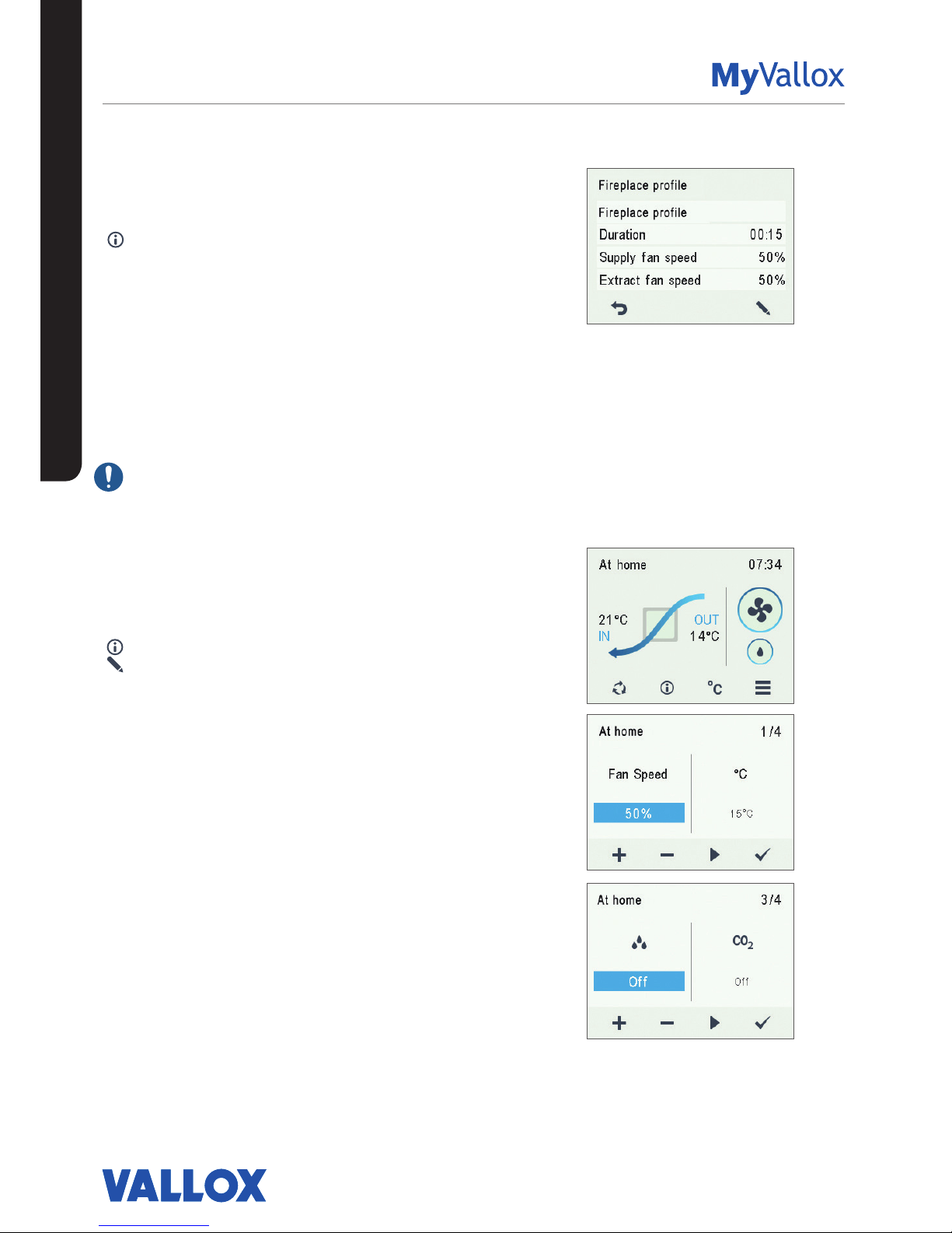
Viewing the Fireplace profile information
1. Open the main display of the Fireplace profile:
2. Select Profile information.
3. The information display shows the following information:
• Duration — Indicates the duration of enhanced
ventilation when the Fireplace profile is activated. The
value is expressed in hours and minutes.
• Supply fan speed — Indicates the percentage of the
supply air fan speed relative to the maximum speed.
• Extract fan speed — Indicates the percentage of the
extract air fan speed relative to the maximum speed.
Modifying and saving the profile settings
IMPORTANT
The unit does not automatically save any settings, not even
those that are currently in use. Unless saved, settings may
be lost during a power cut, for example. To save the settings,
select Expert settings > Save and restore settings.
Modifying profile settings
1. Open the main display of the profile you wish to view.
2. Select Profile information.
3. Select Edit.
4. Make the desired changes as instructed in the section
Setup wizard > Profile settings.
Timer functions of the Boost and Fireplace
profiles
In addition, the timer function can be modified in the Boost
and Fireplace profiles. See Setup wizard -> Profile settings.
VENTILATION PROFILES
Page 25
25
© Vallox Oy - All rights reserved
USING THE UNIT
TEMPERATURES AND SENSORS
Indoor air temperature graph for the
past 24 hours. The outside and supply
air values are shown on a similar display.
You can view the graph for a week or for
a single day.
Indoor air
Outdoor air
Supply air
Exhaust air
1 day
1 week
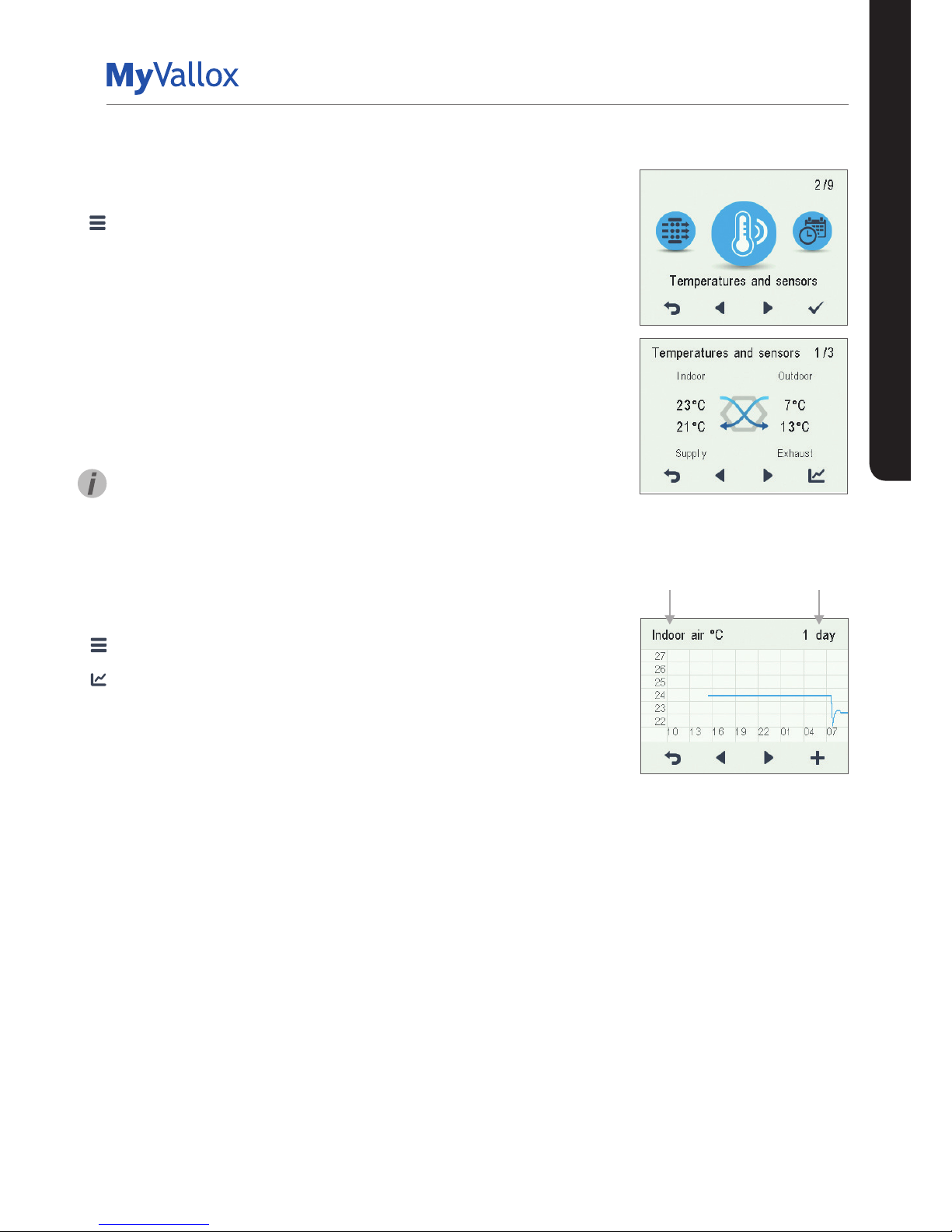
Viewing temperature data
1. Select Settings > Temperatures and sensors.
2. Select OK.
The summary display of temperatures and sensors shows
the following information:
• Indoor — Indicates the temperature of the air flowing into
the unit to be removed from the premises.
• Outdoor — Indicates the temperature of the air flowing
into the unit from outside.
• Supply — Indicates the temperature of the air flowing
into the premises from the unit.
• Exhaust — Indicates the temperature of the exhaust air
flowing outdoors from the unit.
TIP
The temperature and sensor data can also be viewed by
pressing the temperature button on the profile display.
Viewing temperature statistics
1. Select Settings > Temperatures and sensors.
2. Select OK.
3. Select Statistics.
4. A graph appears on the display showing the indoor air
temperature over the past 24 hours.
5. Use the Plus and Minus buttons to alternate between
weekly and daily statistics.
6. Use the arrow buttons to view outdoor air, supply air, and
exhaust air temperature statistics.
7. On each display, use the Plus and Minus buttons to
alternate between weekly and daily statistics.
8. To exit the menu, press the Back button.
Page 26
26
USING THE UNIT
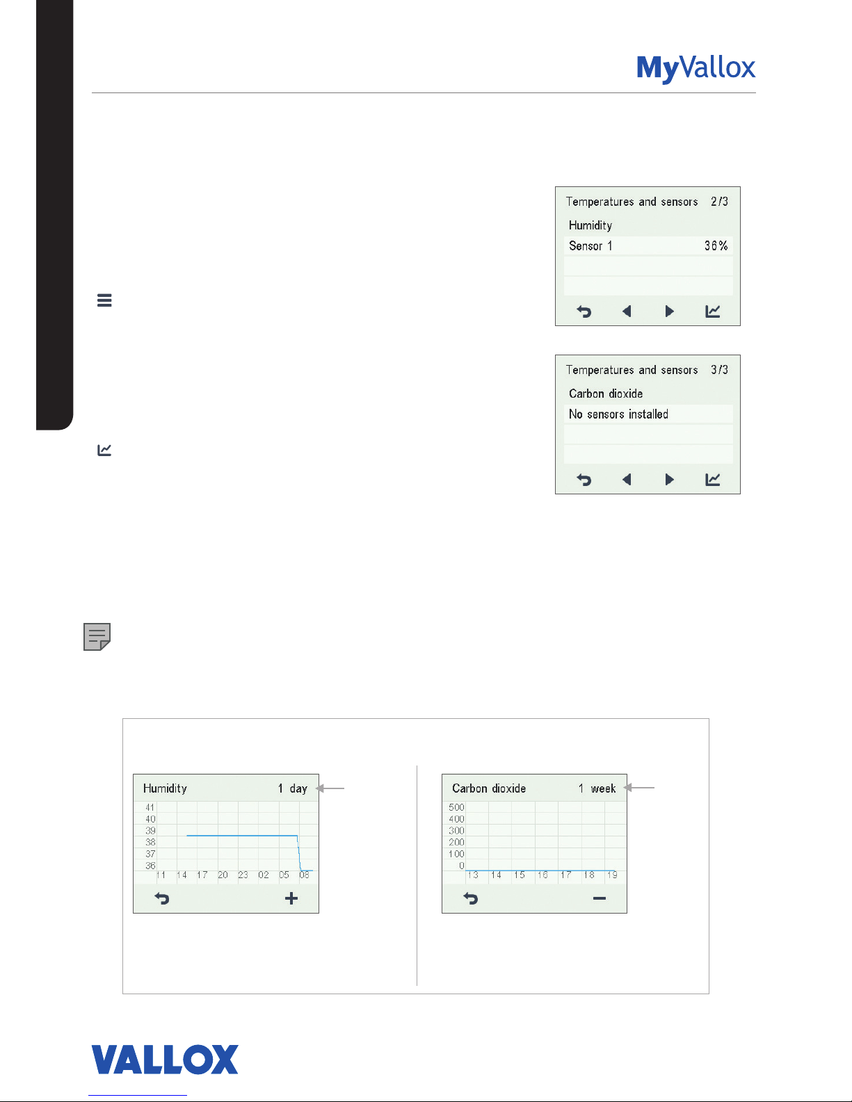
Viewing the relative humidity of air and
carbon dioxide levels measured by the
sensors
To browse levels measured by individual sensors:
1. Select Settings > Temperatures and sensors.
2. Select OK.
3. Use the arrow buttons to switch from the summary
display of Temperatures and sensors to view the relative
humidity of air and carbon dioxide levels measured by
the humidity and carbon dioxide sensors.
To browse statistics for relative humidity of air and carbon
dioxide levels:
1. Select Statistics next to the sensor group you wish to
view.
2. A graph opens on the display showing the relative
humidity of air and carbon dioxide levels recorded over
the past 24 hours by the sensor with the highest values.
3. Use the Plus and Minus buttons to alternate between
weekly and daily statistics.
4. To exit the menu, press the Back button.
NOTE
For more detailed instructions, go to
www.vallox.com
Relative humidity of air statistics for the past 24 hours.
You can view the graph for a week or for a single day.
Carbon dioxide level statistics for the past week. You
can view the graph for a week or for a single day.
1 day
1 week
Relative humidity of air and carbon dioxide level statistics
1 day
1 week
TEMPERATURES AND SENSORS
Page 27
27
© Vallox Oy - All rights reserved
USING THE UNIT
SETTINGS
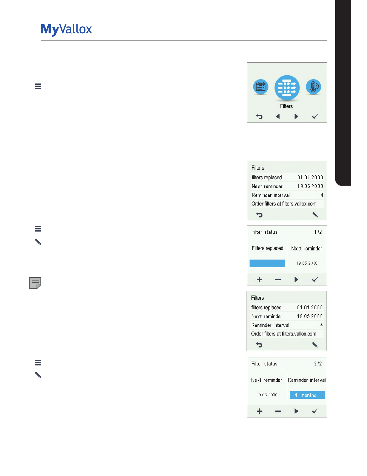
FILTER SETTINGS
1. Select Settings > Filters.
2. Select OK.
3. The summary display of filter replacement shows the
following information:
• Filters replaced — Indicates the date when the filters were
last replaced.
• Next reminder — Indicates the date when a reminder to
replace the filters will next be shown.
• Reminder interval — Indicates the filter replacement interval
in months.
Setting the date the filters were last
replaced
Instructions for replacing the filters are provided in the
Maintenance section.
After replacing the filters, enter the replacement date.
1. Select Settings > Filters.
2. Select OK.
3. Select Edit.
4. Select Plus on the Filter replacement display. The Last
replaced field now reads Today.
5. Select OK.
NOTE
Based on the set reminder interval, the unit will automatically
set the service to provide a reminder to replace the filters at
the due time.
Setting the Filter replacement reminder
interval
1. Select Settings > Filters.
2. Select OK.
3. Select Edit.
4. Select Right arrow.
5. Use the Plus and Minus buttons to set the desired
reminder interval in months in the Reminder interval field.
The interval value can be between 1 and 12 months. The
default setting is 4 months.
6. Select OK.
Page 28
28
USING THE UNIT
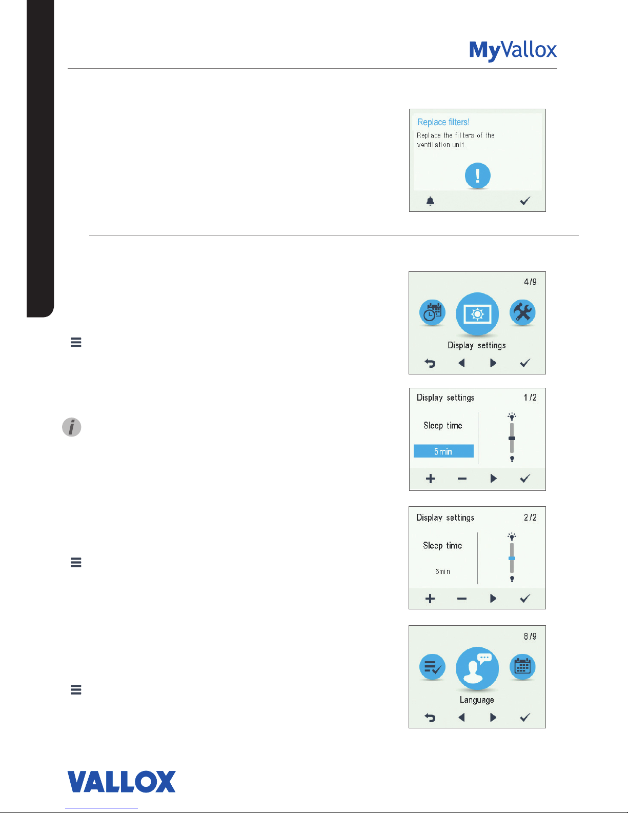
Filter maintenance reminder
The maintenance reminder reminds you of the filter
replacement with a pop-up window.
The message can be acknowledged by selecting OK.
Press the clock button to postpone the reminder for one
week.
DISPLAY SETTINGS
Setting the sleep time
1. Select Settings > Display settings.
2. Select OK.
3. Use the Plus and Minus buttons to set the Sleep time.
4. Select OK.
TIP
The MyVallox Control control panel automatically switches
to the sleep mode when the pre-set Sleep time has elapsed.
To reactivate the MyVallox Control control panel, press any
button.
Adjusting the display brightness
1. Select Settings > Display settings.
2. Select OK.
3. Select Right arrow.
4. Use the Plus and Minus buttons to set the display
brightness.
5. Select OK.
Selecting the user interface language
1. Select Settings > Language.
2. Select OK.
3. Select your language.
4. Select OK.
SETTINGS
Page 29
29
© Vallox Oy - All rights reserved
USING THE UNIT
SETTINGS
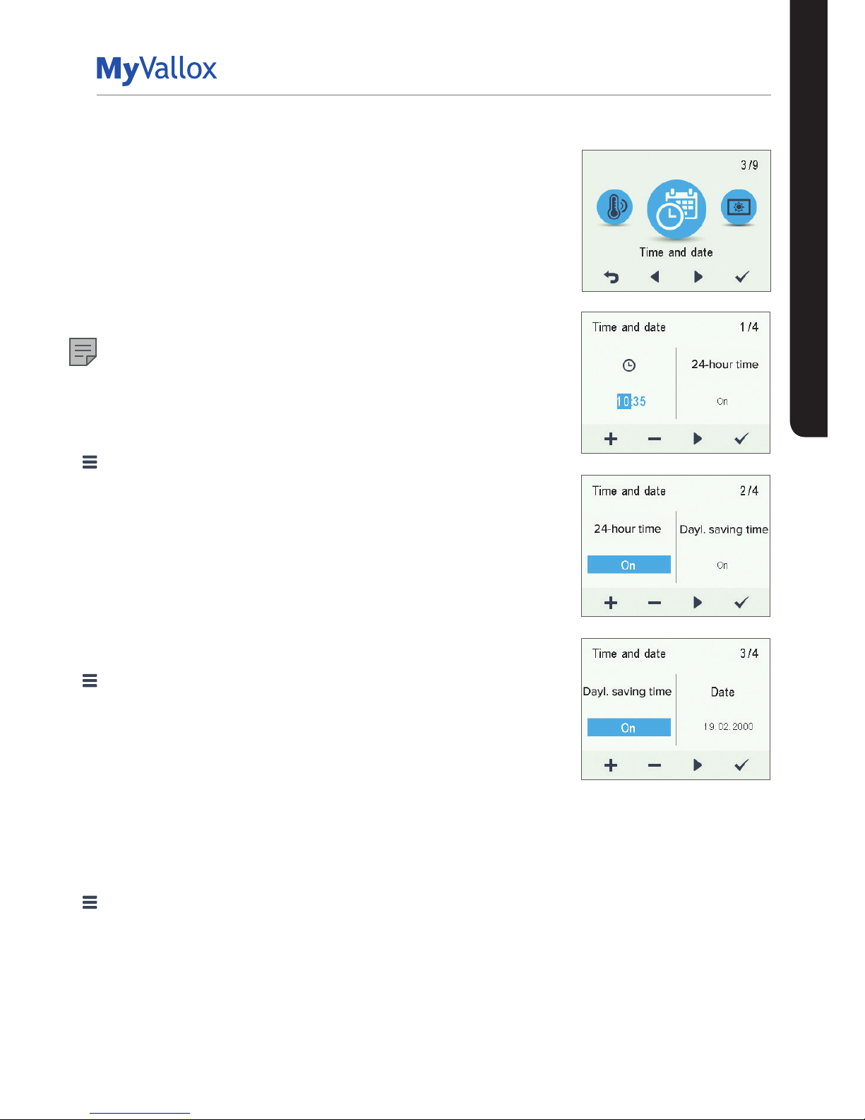
TIME AND DATE
Setting the time and date
The available time settings are:
• Time
• 24- or 12-hour clock
• Automatic daylight saving time
• Date
NOTE
The ventilation unit time will withstand a power cut of a few hours.
Setting the time
1. Select Settings > Time and date.
2. Select OK.
3. Use the Plus and Minus buttons to set the hours.
4. Select Right arrow.
5. Use the Plus and Minus buttons to set the minutes.
6. Select OK.
Selecting the 24- or 12-hour clock
The 24-hour clock is used by default. To use the 12-hour clock:
1. Select Settings > Time and date.
2. Select OK.
3. Select Right arrow until the 2/4 display opens
4. Select Minus. The 24-Hour setting value is changed to O.
5. Select OK.
Automatic daylight saving time
By default, automatic daylight-saving time is turned on. To use the
manual daylight saving time setting:
1. Select Settings > Time and date.
2. Select OK.
3. Select Right arrow until the 3/4 display opens.
4. Select Plus. The Dayl.saving time setting value is changed to O.
5. Select OK.
Page 30
30
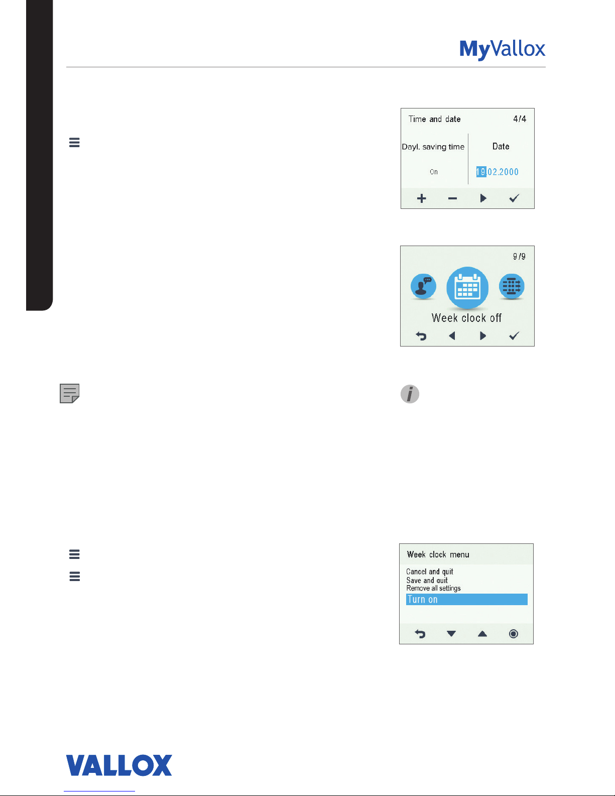
Setting the date
1. Select Settings > Time and date.
2. Select OK.
3. Select Right arrow until the 4/4 display opens.
4. Use the Plus and Minus buttons to set the date.
5. Select Right arrow.
6. Use the Plus and Minus buttons to set the month.
7. Select Right arrow.
8. Use the Plus and Minus buttons to set the year.
9. Select OK.
WEEK CLOCK
The week clock allows you to pre-set a weekly ventilation
program for the ventilation unit. For each hour of the week,
one of the following profiles can be configured:
• At home — The At home profile is used.
• Away — The Away profile is used.
• Boost — The Boost profile is used.
• Blank — Do not change the profile.
NOTE
If you change the profile manually when the week clock is
on, the selected profile will be active until the week clock
switches to the next profile in the program.
If the humidity or carbon dioxide sensors control the
ventilation, they will adjust the fan speed, regardless of
whether the profile has been manually selected or selected
by the week clock.
Turning the week clock on
1. Select Settings > Week clock o.
2. Select OK.
3. Select Settings.
4. Select Turn on.
5. Select Select.
6. The control panel confirms that the week clock is turned
on.
USING THE UNIT
SETTINGS
TIP
You can turn the week clock on
or o by pressing the OK button
on the Week clock display for a
few seconds.
Page 31

31
© Vallox Oy - All rights reserved
USING THE UNIT
SETTINGS
Setting and editing the weekly program
1. Select Settings > Week clock on.
2. Select OK.
3. Use the Right arrow button to select the desired day.
4. Use the Down arrow button to select the desired time.
5. Use the Select button to browse and select the
ventilation profile that will be turned on at the chosen
time. The icons are:
At home profile
Away profile
Boost profile
6. Once you have selected the profiles for the week clock,
select Settings.
7. Select Save and quit, or select Cancel and quit to leave
without saving the week program or the changes made
to it.
8. Once you have saved the week clock program, select
OK on the confirmation display.
Turning the Week clock o
1. Select Settings > Week clock on.
2. Select OK.
3. Select Settings.
4. Select Turn o.
5. Select Select.
6. The control panel will confirm that the week clock is
turned off.
7. The week clock is now turned off. If you have set a
weekly program, it will be saved in the unit.
Removing the week clock settings
To delete the weekly program settings:
1. Select Settings > Week clock on or Week clock o.
2. Select OK.
3. Select Settings.
4. Select Remove all settings.
5. Select OK to accept deletion of the weekly program. The
weekly program has now been deleted.
Page 32

32
Example of setting a weekly program
In this example, the following weekly program has been set:
• Mon-Fri 8-17, Away .
• Mon-Fri 17-07, At home.
• Sat 8-17, At home.
• Sat 18-20, At home with a ventilation boost needed for
cooking, for example.
• Sat 21-Mon 8, At home.
To set the week clock, proceed as follows:
1. Open the week clock.
2. Select Monday, and input the following settings:
• For 08:00, select the Away profile.
• For 17:00, select the At home profile.
3. Then input the corresponding settings for the other
weekdays.
4. Then select Saturday, and input the following settings:
• At 18, select the Boost profile.
• At 21, select the At home profile.
5. Ensure that the Week clock is turned on.
6. The weekly program has now been set.
USING THE UNIT
TURNING THE UNIT OFF
To turn the ventilation unit o:
1. Select Settings> Turn unit o.
2. Select OK.
3. Accept the command by selecting OK.
4. The ventilation unit has now been turned off.
IMPORTANT
In order to ensure that the indoor air presents no harm
to health and remains optimal for the structures of the
building, ventilation must be kept on without disruptions. It is
recommended that ventilation be left turned on during long
holidays also. This keeps the indoor air fresh and prevents
humidity from condensing in the ventilation ducts and
structures. It also reduces the risk of moisture damage.
TIP
To re-start the ventilation unit, press any key.
The figures above show the
aforementioned settings in the
week clock.
SETTINGS
Page 33

33
© Vallox Oy - All rights reserved
USING THE UNIT
TROUBLESHOOTING
NOTE
Error messages are displayed on the control panel and in the
MyVallox Home and MyVallox Cloud services.
CONDENSING WATER USER
In the heating season, the extract air humidity condenses
to water. In new buildings, condensation runo can form
rapidly. Condensed water must be able to freely leave the
unit.
At some time before the heating season begins (e.g. during
autumn maintenance), check that the water seal or the
condensing water outlet in the bottom pool are not clogged.
To check this, pour some water into the pool. Clean as
required.
FA U LT CAUSE MEASURES
Error message:
Extract air fan stopped
The extract air fan has stopped. Make sure that the fan is not running. The fan cabling
and operation must be checked, and if necessary the
fan must be replaced. Contact the service centre.
Error message:
Supply air fan stopped
The supply air fan has stopped. Make sure that the fan is not running. The fan cabling
and operation must be checked, and if necessary the
fan must be replaced. Contact the service centre.
Error message:
Temperature sensor 1/2/3/4/5
The temperature sensor indicated
on the user interface is damaged.
The sensor installation must be checked, and if
required the sensor must be replaced. Contact the
service centre.
Error message:
Bus fault
Problems with the data transfer
bus.
Make sure that the Modbus bus is connected correctly,
and that the devices connected to it are properly
functioning.
The ventilation unit is not
working; the control panel is
not working.
Power input to the unit is lost or the
safety switch catch of the door is
not touching the safety switch.
Check:
• Fuse in the fuse box
• Fuse in the unit
• Press the safety switch all the way down and test if
the unit can be turned on. If the unit can be turned
on, ensure that the safety switch catch is touching
the safety switch.
The ventilation unit is working,
but the control panel is not
working.
Either the control panel 24 VDC
power is lost, there is a problem
with data transmission, or the
control panel is damaged.
Check the cables from the unit to the control panel.
Contact the service centre if necessary.
NOTE
Some condensing water may
have accumulated in the bottom
pool of the unit; this is normal
and requires no corrective
action.
WARNING
Water must at all times be kept
out of the electrical system.
Page 34

MAINTENANCE
34
BEFORE BEGINNING MAINTENANCE WORK
The safety switch (S) automatically turns o the power when the door of the unit is opened.
WARNING
Always disconnect the power plug before starting the ventilation unit maintenance.
MAINTENANCE
There are two unit models, left- (L) and right-handed (R). In the
right handed version, outdoor air blows into the unit from the
right side of the centre line as shown in the instructions. In the
left handed version, outdoor air blows into the unit from the left
side. Also the position of the filters, bypass flap, and heating
radiator is mirrored in the left-handed model.
REPLACING THE FILTERS USER
When the maintenance reminder becomes activated, check
the cleanliness of the filters and replace them if required. The
ventilation unit has three air filters:
• Class G4 coarse filter (A) filters insects, heavy pollen and
other relatively large foreign objects out of the outdoor air.
• Class F7 fine filter (B) filters microscopic pollen and dust
particles out of the supply air.
• Class G4 coarse filter (C) filters the extract air and keeps the
heat recovery cell clean.
To replace the filters:
1. Disconnect the ventilation unit from the mains electricity
supply.
2. Open the door of the unit.
3. Lift the door off.
4. Remove the old filters (A, B, C) and discard them.
5. Install the new filters (A, B, C).
6. Close the door of the unit. Ensure that the safety switch
catch of the door is touching the safety switch, allowing the
unit to be turned on.
7. Plug the ventilation unit back into the mains.
8. The filters have now been successfully replaced.
S
C
A
B
NOTE
Using original Vallox filters
ensures that the ventilation
unit remains in top condition,
giving the best results. The
filter replacement interval
depends on the ambient
dust concentration. It is
recommended that the filters
be replaced every spring and
autumn, or at the very least
once a year.
Page 35

35
© Vallox Oy - All rights reserved
MAINTENANCE
CLEANING THE HEAT RECOVERY CELL
USER
Check that the heat recovery cell (D) is clean roughly once a
year when the filters are being replaced. Clean by washing as
required.
IMPORTANT
Handle the cell carefully! For example, do not lift the cell by the
layers. The cell layers are very thin and easily damaged.
To check the heat recovery cell (HR cell):
1. Disconnect the ventilation unit from the mains electricity
supply.
2. Lift the latch to open the door of the ventilation unit.
3. Lift the door off.
4. Pull the G4 filters (A, C) and filter supports out of the unit.
5. Remove the sealing strip (E) above the HR cell.
6. Remove the side sealing strip (F).
7. Remove the G7 filter (B).
8. Lift and pull the cell (D) out of the unit.
9. If the cell is dirty, clean it by immersing it in warm water, to
which a small amount of a mild detergent has been added.
10. Rinse the cell clean with a water spray. Do not use a highpressure cleaner.
11. When all the water has drained from between the layers,
reassemble the ventilation unit in the reverse order.
12. Close the door. Ensure that the safety switch catch of the
door is touching the safety switch.
13. Plug the ventilation unit back into the mains.
14. The heat recovery cell has now been checked and cleaned.
IMPORTANT
If the unit has an enthalpy cell, it must not be washed. Only
aluminium or plastic cells can be washed.
Page 36

36
MAINTENANCE
CLEANING THE FANS INSTALLER
Check the cleanliness of the fans when servicing the filters
and the heat recovery cell. Clean the fans as required.
You can clean the fan blades with compressed air (wear
protective goggles) or by brushing them gently. Do not
remove or move the fan blade balancing weights.
IMPORTANT
The fans are extremely sensitive to external shocks. It is
recommended that the fans be cleaned in place, i.e. without
attempting to remove them. Remove the fan beds and
the bypass duct carefully in accordance with the below
instructions to prevent damage to the unit. The small size of
the unit restricts the space available for servicing.
IMPORTANT
Handle the fan blades carefully. Do not remove or move the
fan blade balancing weights.
Cleaning the supply air fan
The steps are mirrored for the left handed unit.
To remove and clean the supply air fan:
1. Disconnect the ventilation unit from the mains electricity
supply.
2. Unfasten the four screws to open the door of the unit.
3. Lift the door off.
4. Remove the extract air filter (C), the cell top bracket (E)
and the heat recovery cell (D), as described in sections
“Filters” and “Heat recovery cell”.
5. Remove the mounting screws of the fan bed (2 pcs).
6. Pull the bypass duct/filter stand package out of the unit
and turn to the right.
7. Remove the cable connector (black) of the fan and move
the supply air fan slightly to the right.
8. Remove the post-heating radiator connector. The post
heating radiator connector can be removed once the
supply air fan has been moved slightly to the right.
9. Tilt the supply air fan to the right and push the
connectors out of the way. Turn the fan 90° and tilt it
forward to pull it out of the unit.
10. The fan has now been removed for cleaning.
11. To reassemble the ventilation unit, follow the above
steps in reverse order.
12. Close the door. Ensure that the safety switch catch of the
door is touching the safety switch.
13. Plug the ventilation unit back into the mains.
The fan has now been checked and cleaned.
NOTE
The steps are mirrored for the left
handed unit.
Page 37

37
© Vallox Oy - All rights reserved
MAINTENANCE
Cleaning the extract air fan
To remove and clean the extract air fan:
1. Disconnect the ventilation unit from the mains
electricity supply.
2. Lift the latch to open the door of the ventilation
unit.
3. Lift the door off.
4. Remove the extract air filter (C), the cell top
bracket (E) and the heat recovery cell (D), as
described in sections “Filters” and “Heat recovery
cell”.
5. Remove the fan bed mounting screw (see
removing the supply air fan, Figure 1).
6. Remove the connector package from the wall.
7. Separate the connectors from each other.
8. Tilt the fan to the left and turn 90°.
9. Tilt the fan forward to pull it out of the unit.
10. The fan has now been removed for cleaning.
11. To reassemble the ventilation unit, follow the
above steps in reverse order.
12. Close the door. Ensure that the safety switch catch
of the door is touching the safety switch.
13. Plug the ventilation unit back into the mains.
The fan has now been checked and cleaned.
NOTE
Install the fan beds in a reverse order.
NOTE
The steps are mirrored for the left
handed unit.
Page 38

38
B
C
A
BEFORE BEGINNING
MAINTENANCE WORK
The safety switch (S) automatically turns o the
power when the door of the unit is opened.
WARNING
Always disconnect the power plug before starting
the ventilation unit maintenance.
There are two unit models, left- (L) and righthanded (R). The figure shows the right-handed
model. In the right handed version, outdoor air
blows into the unit from the right side of the centre
line as shown in the instructions. In the left handed
version, outdoor air blows into the unit from the left
side. Also the position of the filters, bypass flap,
and heating radiator is mirrored in the left-handed
model.
REPLACING THE FILTERS
USER
When the maintenance reminder becomes
activated, check the cleanliness of the filters and
replace them if required.
The Vallox ventilation unit has three air filters:
• Class G4 coarse filter filters insects, heavy
pollen and other relatively large foreign objects
out of the outdoor air.
• Class F7 fine filter filters microscopic pollen
and dust particles out of the supply air.
• Class G4 coarse filter filters the extract air and
keeps the heat recovery cell clean.
The filter replacement interval depends on the
ambient dust concentration. It is recommended
that the filters be replaced every spring and
autumn, or at the very least once a year.
To replace the filters:
1. Disconnect the ventilation unit from the mains
electricity supply.
2. Open the upper door of the unit.
3. Remove the old filters (A, B, C) and discard
them.
4. Install the new filters (A, B, C).
5. Close the door of the unit. Ensure that the
safety switch catch of the door is touching the
safety switch, allowing the unit to be turned on.
6. Plug the ventilation unit back into the mains.
7. The filters have now been successfully
replaced.
D
S
B
C
A
E
F
G
TIP
Using original Vallox filters ensures
that the ventilation unit remains in top
condition, giving the best results.
MAINTENANCE
Page 39

39
© Vallox Oy - All rights reserved
MAINTENANCE
CLEANING THE HEAT RECOVERY
CELL USER
Check that the heat recovery cell is clean roughly once a
year, or whenever the filters are being replaced. Clean by
washing as required.
IMPORTANT
If the unit has an enthalpy cell, it must not be washed. Only
aluminium or plastic cells can be washed.
To check and clean the heat recovery cell:
1. Disconnect the ventilation unit from the mains electricity
supply.
2. Lift the latch to open the door of the ventilation unit and
lift the door off.
CAUTION
The door is heavy.
3. Remove the filters (A, B, C).
4. Remove the sealing strip (E) above the cell in the
direction of the arrow.
5. Lift and pull the cell (D) out of the unit.
IMPORTANT
Handle the cell carefully! For example, do not lift the cell by
the layers. The cell layers are very thin and easily damaged.
6. If the cell is dirty, clean it by immersing it in warm water,
to which a small amount of a mild detergent has been
added.
7. Rinse the cell clean with a water spray. Do not use a
high-pressure cleaner.
8. When all the water has drained from between the layers,
reassemble the ventilation unit in the reverse order.
9. Close the door and ensure that the safety switch catch of
the door is engaged.
10. Plug the ventilation unit back into the mains. The heat
recovery cell has now been checked and cleaned.
D
E
D
E
Page 40

40
MAINTENANCE
Removing and cleaning the supply air fan (A)
To clean the supply air fan:
1. Disconnect the ventilation unit from the mains electricity
supply.
2. Lift the latch to open the door of the Vallox ventilation unit.
3. Lift the door off.
CAUTION
The door is heavy.
4. Remove the fine filter (1). To do so, pull the fine filter out of
the unit.
5. The fan has been fastened on the mounting plate with
wing bolts (2). Remove the wing bolts and lift the fan out of
the unit.
6. Disconnect the quick connector (3) of the fan cable.
7. Clean the fan. The fan blades can be cleaned with
compressed air (wear protective goggles) or by brushing
them gently. Do not remove or move the fan blade
balancing weights.
8. To reassemble the ventilation unit, follow the above steps
in reverse order.
9. Close the door. Ensure that the safety switch catch of the
door is touching the safety switch.
10. Plug the ventilation unit back into the mains.
Removing and cleaning the extract air fan (B)
To clean the extract air fan:
1. Disconnect the ventilation unit from the mains electricity
supply.
2. Lift the latch to open the door of the ventilation unit.
3. Lift the door off.
CAUTION
The door is heavy.
4. The fan has been fastened on the mounting plate with
wing bolts. Remove the wing bolts and lower the fan out of
the unit.
5. Disconnect the quick connector of the fan cable.
6. Clean the fan. The fan blades can be cleaned with
compressed air (wear protective goggles) or by brushing
them gently. Do not remove or move the fan blade
balancing weights.
7. To reassemble the ventilation unit, follow the above steps
in reverse order.
8. Close the door. Ensure that the safety switch catch of the
door is touching the safety switch.
9. Plug the ventilation unit back into the mains.
CLEANING THE FANS INSTALLER
Check the cleanliness of the fans when servicing the filters and the heat
recovery cell. Clean the fans as required.
B
A
2
2
1
B
A
3
2 x
IMPORTANT
The fans are extremely
sensitive to external shocks. It
is recommended that the fans
be cleaned in place, i.e. without
attempting to remove them.
Handle the fan blades carefully.
Do not remove or move the fan
blade balancing weights.
Page 41

41
© Vallox Oy - All rights reserved
MAINTENANCE
BEFORE BEGINNING MAINTENANCE
WORK
The safety switch automatically turns o the power when the door
of the unit is opened.
WARNING
Always disconnect the power plug before starting the ventilation
unit maintenance.
There are two unit models, left- (L) and right-handed (R).
REPLACING THE FILTERS USER
See section Vallox 90 MV, Replacing the filters.
CLEANING THE HEAT RECOVERY CELL
USER
See section Vallox 90 MV, Cleaning the heat recovery cell.
CLEANING THE FANS INSTALLER
See section Vallox 90 MV, Cleaning the fans.
CLEANING THE GREASE FILTER OF THE
COOKER HOOD USER
Clean the grease filter of the cooker hood 1-2 times a month.
To clean the grease filter:
1. Open the quick connectors of the bottom plate of the cooker
hood by pressing them.
2. Let the bottom plate move to the down position.
3. Remove the grease filter from its mountings.
4. Clean the grease filter either by washing it with hot water and
hand-washing detergent or in a dishwasher.
REPLACING THE COOKER HOOD LAMP
USER
To replace the cooker hood lamp (type PL 11, 11 W), remove the
protective glass of the lamp (A) by pushing it to the left. Once you
have replaced the lamp, put the protective glass back in its place.
A
1
2
Page 42

42
MAINTENANCE
BEFORE BEGINNING MAINTENANCE WORK
The safety switch (S) automatically turns o the power when the door of the unit is opened.
WARNING
Always disconnect the power plug before starting the ventilation unit maintenance.
There are two unit models, left- (L) and right-handed (R). The figure shows the right-handed model.
REPLACING THE FILTERS USER
When the maintenance reminder becomes activated, check
the cleanliness of the filters and replace them if required.
The Vallox ventilation unit has three air filters:
• Class G4 coarse filter filters insects, heavy pollen and
other relatively large foreign objects out of the outdoor
air.
• Class F7 fine filter filters microscopic pollen and dust
particles out of the supply air.
• Class G4 coarse filter filters the extract air and keeps the
heat recovery cell clean.
The filter replacement interval depends on the ambient dust
concentration. It is recommended that the filters be replaced
every spring and autumn, or at the very least once a year.
NOTE
Using original Vallox filters ensures that the ventilation unit
remains in top condition, giving the best results.
C
B
S
A
Page 43

43
© Vallox Oy - All rights reserved
MAINTENANCE
To replace the filters:
1. Disconnect the ventilation unit from the mains electricity supply.
2. Open door of the Vallox ventilation unit by undoing the finger
screws.
3. Lift the door off.
CAUTION
The door is heavy.
4. Remove the old filters (A, B, C) and discard them.
5. Install the new filters (A, B, C).
6. Close the door of the unit. Ensure that the safety switch catch
of the door is touching the safety switch, allowing the unit to be
turned on.
7. Plug the ventilation unit back into the mains.
The filters have now been successfully replaced.
CLEANING THE HEAT RECOVERY CELL
USER
Check that the heat recovery cell is clean roughly once a year,
or whenever the filters are being replaced. Clean by washing as
required.
To check and clean the heat recovery cell:
1. Disconnect the ventilation unit from the mains electricity supply.
2. Open door of the Vallox ventilation unit by undoing the finger
screws.
3. Lift the door off.
CAUTION
The door is heavy.
4. Remove the sealing strip (E) above the HR cell in the direction of
the arrow.
5. Remove the extract air filter (C).
6. Lift and pull the HR cell (D) out of the unit.
7. If the cell is dirty, clean it by immersing it in warm water, to which
a small amount of a mild detergent has been added.
8. Rinse the cell clean with a water spray. Do not use a highpressure cleaner.
9. When all the water has drained from between the layers,
reassemble the ventilation unit as follows:
10. Ensure that the lower support (F) is in place between the knobs
at the bottom of the unit.
11. Push the heat recovery cell in place.
12. Push the sealing strip (E) in place so that the strip is supported by
the corner bracket (G) at the rear.
13. Install the extract air filter (C) in place.
14. Close the door. Ensure that the safety switch catch of the door is
touching the safety switch.
15. Plug the ventilation unit back into the mains.
The heat recovery cell has now been checked and cleaned.
IMPORTANT
Handle the cell carefully! For
example, do not lift the cell by
the layers. The cell layers are
very thin and easily damaged.
IMPORTANT
If the unit has an enthalpy cell,
it must not be washed. Only
aluminium or plastic cells can
be washed.
D
C
G
E
F
Page 44

44
MAINTENANCE
CLEANING THE FANS INSTALLER
Check the cleanliness of the fans when servicing the filters and the heat
recovery cell. Clean the fans as required.
You can clean the fan blades with compressed air (wear protective
goggles) or by brushing them gently. Do not remove or move the fan
blade balancing weights.
To clean the fan:
1. Disconnect the ventilation unit from the mains electricity supply.
2. Open door of the Vallox ventilation unit by undoing the finger screws.
3. Lift the door off.
CAUTION
The door is heavy.
4. Remove the extract air filter (C), the sealing strip (E) and the heat
recovery cell (D). See chapters “Replacing the filters” and “Cleaning
the heat recovery cell”.
5. Disconnect the quick connector (H) of the supply air fan (T) and/or the
extract air fan (P) cables.
6. Push the fan cables and the rubber feed through (I) into the fan
chamber.
7. Remove the wing screws used to fasten the fans (J) (3 screws per fan).
8. Remove the fan from the unit by pulling it forward and by tilting it
slightly backwards at the same time.
9. Remove the mounting screws (K) (4 screws) of the air flow control
grille of the supply air fan and remove the grille. You can now clean
the fan. Put the control grille back in place after cleaning.
10. Reassemble in reverse order after cleaning. Ensure that the rubber
feed throughs set in place when reinstalling the fan.
11. Close the door. Ensure that the safety switch catch of the door is
touching the safety switch.
12. Plug the ventilation unit back into the mains.
The fan has now been checked and cleaned.
IMPORTANT
The fans are extremely
sensitive to external shocks. It
is recommended that the fans
be cleaned in place, i.e. without
attempting to remove them.
Handle the fan blades carefully.
Do not remove or move the fan
blade balancing weights.
T
P
D
C
E
I
T
P
H
J
J
K
S
Page 45

45
© Vallox Oy - All rights reserved
45
© Vallox Oy - All rights reserved
BEFORE BEGINNING MAINTENANCE WORK
The safety switch (S) automatically turns o the power when the door of the unit is opened.
WARNING
Always disconnect the power plug before starting the ventilation unit maintenance.
There are two unit models, left- (L) and right-handed (R). The figure shows the right-handed model.
REPLACING THE FILTERS USER
When the maintenance reminder becomes activated, check
the cleanliness of the filters and replace them if required.
The Vallox ventilation unit has three air filters:
• Class G4 coarse filter filters insects, heavy pollen and other
relatively large foreign objects out of the outdoor air.
• Class F7 fine filter filters microscopic pollen and dust
particles out of the supply air.
• Class G4 coarse filter filters the extract air and keeps the
heat recovery cell clean.
The filter replacement interval depends on the ambient dust
concentration. It is recommended that the filters be replaced
every spring and autumn, or at the very least once a year.
NOTE
Using original Vallox filters ensures that the ventilation unit
remains in top condition, giving the best results.
MAINTENANCE
Page 46

4646
To replace the filters:
1. Disconnect the ventilation unit from the mains electricity supply.
2. Lift the latch to open the door of the Vallox ventilation unit.
3. Lift the door off.
CAUTION
The door is heavy.
4. Remove the old filters (A, B, C) and discard them.
5. Install the new filters (A, B, C).
6. Close the door of the unit. Ensure that the safety switch catch
of the door is touching the safety switch, allowing the unit to be
turned on.
7. Plug the ventilation unit back into the mains.
The filters have now been successfully replaced.
CLEANING THE HEAT RECOVERY CELL
USER
Check that the heat recovery cell is clean roughly once a year,
or whenever the filters are being replaced. Clean by washing as
required.
To check and clean the heat recovery cell:
1. Disconnect the ventilation unit from the mains electricity supply.
2. Open the Vallox ventilation unit door by first lifting the latch
fully up and then lowering it back a little way.
3. Lift the door off.
CAUTION
The door is heavy.
4. Remove the filters (A, B, C).
5. Remove the sealing strip (E) above the cell in the direction of
the arrow.
6. Lift and pull the cell (D) out of the unit.
7. If the cell is dirty, clean it by immersing it in warm water, to
which a small amount of a mild detergent has been added.
8. Rinse the cell clean with a water spray. Do not use a highpressure cleaner.
9. When all the water has drained from between the layers,
reassemble the ventilation unit in the reverse order.
10. When reassembling Vallox 096 MV, check that the sealing strip
below the cell is pressed against the bottom of the unit.
11. Close the door. Ensure that the safety switch catch of the door
is touching the safety switch.
12. Plug the ventilation unit back into the mains.
The heat recovery cell has now been checked and cleaned.
IMPORTANT
Handle the cell carefully! For
example, do not lift the cell by
the layers. The cell layers are
very thin and easily damaged.
MAINTENANCE
IMPORTANT
If the unit has an enthalpy cell,
it must not be washed. Only
aluminium or plastic cells can
be washed.
Page 47

47
© Vallox Oy - All rights reserved
47
© Vallox Oy - All rights reserved
CLEANING THE FANS INSTALLER
Check the cleanliness of the fans when servicing the filters and the
heat recovery cell. Clean the fans as required.
You can clean the fan blades with compressed air (wear protective
goggles) or by brushing them gently. Do not remove or move the fan
blade balancing weights.
Cleaning the supply air fan
To clean the supply air fan:
1. Disconnect the ventilation unit from the mains electricity supply.
2. Lift the latch to open the door of the Vallox ventilation unit.
3. Lift the door off.
CAUTION
The door is heavy.
4. Remove the extract air filter (C), the cell top bracket (E) and the
heat recovery cell (D). See chapters “Replacing the filters” and
“Cleaning the heat recovery cell”.
5. Pull out the temperature sensor (figure 1) located at the top of the
extract air duct (G). Remove the stopper screw (I) at the bottom
of the duct. The extract air duct now comes out by turning and
pushing it downwards simultaneously (figure 2).
6. Remove the temperature sensor from the resistance support (figure 4).
7. Remove the additional and post-heating radiator support, which
is attached by two wing nuts (Vallox 110 MV and Vallox 145 MV) or
screws (Vallox 096 MV) from below (figure 5).
1 1
det
32
4 5 6 7
MAINTENANCE
IMPORTANT
The fans are extremely
sensitive to external shocks. It
is recommended that the fans
be cleaned in place, i.e. without
attempting to remove them.
Handle the fan blades carefully.
Do not remove or move the fan
blade balancing weights.
Page 48

4848
8. Pull the radiator and the support out of the unit (figures
6 and 7) and remove the quick connector of the radiator
wires.
CAUTION
Before removing the resistor from the unit, make sure it is
not hot.
9. The fan can now be cleaned in place. It is recommended
that the fan be cleaned in place, i.e. without attempting
to remove it.
10. To remove the fan for cleaning:
a. If necessary, remove the arm pins. Use pliers to press
the pins straight, so that they are easier to install back
later.
b. Push the fan gently upward (figure 9).
c. Pry the plastic lock to the right of the fan with a
screwdriver, for example (figure 10).
d. The fan falls downwards.
e. Pull the fan out of the unit (figure 11).
f. Disconnect the fan wire quick connector (figure 12).
The fan has now been removed for cleaning.
11. To reassemble the ventilation unit, follow the above
steps in reverse order.
TIP
When you re-install the temperature sensor, position it with
the tip upward and pointing at the wall in such a way that it
does not get squeezed between the bypass plate or lean
against the radiator frame.
12. Close the door. Ensure that the safety switch catch of the
door is touching the safety switch.
13. Plug the ventilation unit back into the mains.
The fan has now been checked and cleaned.
8
10
9
11
12
MAINTENANCE
Page 49

49
© Vallox Oy - All rights reserved
49
© Vallox Oy - All rights reserved
Cleaning the extract air fan
To clean the extract air fan, proceed as follows:
1. Disconnect the ventilation unit from the mains electricity supply.
2. Lift the latch to open the door of the Vallox ventilation unit.
3. Lift the door off.
CAUTION
The door is heavy.
4. Remove the filters (C), the cell top support (E) and the heat recovery cell
(D). See chapters “Replacing the filters” and “Cleaning the heat recovery
cell”.
5. Open the four screws (figure 1) on the extract air fan cover and remove
the cover (figure 2). The fan can now be cleaned in place.
6. To remove the fan for cleaning:
a. Push the fan gently upward (figure 3).
b. Pry the plastic lock to the right of the fan with a screwdriver, for
example (figure 4).
c. The fan falls downwards (figure 5).
d. Pull the fan out of the unit.
e. Disconnect the fan wire quick connector (figure 6).
7. Clean the fan.
8. To reassemble the ventilation unit, follow the above steps in reverse
order.
9. Close the door and plug the unit back into the mains. The extract air fan
has now been checked and cleaned.
1 32
4 5 6
MAINTENANCE
Page 50

50
MAINTENANCE
BEFORE BEGINNING
MAINTENANCE WORK
The safety switch automatically turns o the power when
the upper door of the unit is opened.
WARNING
Always disconnect the power plug before starting the
ventilation unit maintenance.
Opening and closing the doors
1. Lift the latches to open the upper door of the
ventilation unit.
2. Lift the upper door off.
CAUTION
The door is heavy.
3. Open the lower door of the ventilation unit by
undoing the finger screws.
4. Lift the lower door off.
5. Close the doors in reverse order.
There are two unit models, left- (L) and right-handed (R).
The figure shows the right-handed model.
REPLACING THE FILTERS USER
When the maintenance reminder becomes activated,
check the cleanliness of the filters and replace them if
required.
The Vallox ventilation unit has three air filters:
• Class G4 coarse filter filters insects, heavy pollen
and other relatively large foreign objects out of the
outdoor air.
• Class F7 fine filter filters microscopic pollen and dust
particles out of the supply air.
• Class G4 coarse filter filters the extract air and keeps
the heat recovery cell clean.
The filter replacement interval depends on the ambient
dust concentration. It is recommended that the filters be
replaced every spring and autumn, or at the very least
once a year.
NOTE
Using original Vallox filters ensures that the ventilation
unit remains in top condition, giving the best results.
Page 51

51
© Vallox Oy - All rights reserved
MAINTENANCE
To replace the filters:
1. Disconnect the ventilation unit from the mains electricity
supply.
2. Open the upper door of the unit.
3. Remove the old filters (A, B, C) and discard them.
4. Install the new filters (A, B, C).
5. Close the door of the unit. Ensure that the safety switch
catch of the door is touching the safety switch, allowing
the unit to be turned on.
6. Plug the ventilation unit back into the mains.
The filters have now been successfully replaced.
CLEANING THE HEAT RECOVERY
CELLS USER
Check that the heat recovery cells are clean roughly once a
year when the filters are being changed. Clean by washing
as required.
IMPORTANT
If the unit has an enthalpy cell, it must not be washed. Only
aluminium or plastic cells can be washed.
To check and clean the heat recovery cell:
1. Disconnect the ventilation unit from the mains electricity
supply.
2. Open the doors of the unit.
3. Remove the filters (A, B, C).
4. Remove the support grid of the filters.
5. Disengage the upper support strip (D) of the cell.
6. Lift and pull the cell (E) out of the unit.
7. If the cells are dirty, clean them by immersing it in warm
water, to which a small amount of a mild detergent has
been added.
8. Rinse the cell clean with water spray. Do not use a highpressure cleaner.
9. When all the water has drained from between the layers,
reassemble the ventilation unit in the reverse order.
10. Close the doors. Ensure that the safety switch catch of
the door is touching the safety switch.
11. Plug the ventilation unit back into the mains.
The heat recovery cells have now been checked and
cleaned.
IMPORTANT
Handle the cells carefully! For
example, do not lift the cells by
the layers. The cell layers are
very thin and easily damaged.
D
E
A
B
C
Page 52

52
NOTE
Only the supply air fan is
equipped with a sound-damping
grid.
MAINTENANCE
Removing and cleaning the supply and extract
air fans
To clean the supply air fan:
1. Disconnect the ventilation unit from the mains electricity supply.
2. Open the doors of the unit.
3. Pull the temperature sensor out of the rubber feed through (A).
4. Disconnect the quick connector (B) of the fan cables.
5. Remove the rubber feed through (C).
6. Undo the fan’s mounting screws.
7. Pull the fan out of its housing.
8. Clean the fan.
9. To reassemble the ventilation unit, follow the above steps in
reverse order.
10. Close the doors. Ensure that the safety switch catch of the door
is touching the safety switch.
11. Plug the ventilation unit back into the mains.
The fan has now been checked and cleaned.
Clean the extract air fan in the same way. The extract air fan is
located symmetrically on the opposite side of the unit.
CLEANING THE FANS INSTALLER
Check the cleanliness of the fans when servicing the filters and the heat recovery cell. Clean the fans as
required.
You can clean the fan blades with compressed air (wear protective goggles) or by brushing them gently.
IMPORTANT
The fans are extremely
sensitive to external shocks. It
is recommended that the fans
be cleaned in place, i.e. without
attempting to remove them.
Handle the fan blades carefully.
Do not remove or move the fan
blade balancing weights.
NOTE
Remember to replace the
temperature sensor by feeding
it through the rubber feed.
A
B
C
Page 53

53
© Vallox Oy - All rights reserved
10 x
2 x
WARNING
Risk of fire! Connect the cables
so that they do not touch the
resistor.
CAUTION
Before removing the resistor
from the unit, make sure it is not
hot.
REMOVING THE RESISTOR
To remove the resistor:
1. Disconnect the ventilation unit from the
mains electricity supply.
2. Open the doors of the unit.
3. Open the resistor box by undoing the
mounting screws (10 PZ2 screws).
4. Remove the quick connector of the
resistor:
a. Press down the locking device.
b. Pull o the connector.
5. Undo the two wing nuts connecting the
resistor to the ventilation unit.
6. Lift the resistor out of the ventilation unit.
7. To reassemble the ventilation unit, follow
the above steps in reverse order.
MAINTENANCE
Page 54

54
GENERAL INSTALLATION INSTRUCTIONS
WARNING
Water must at all times be kept
out of the electrical system.
INSTALLATION SITE
The Vallox ventilation unit must be installed in a
location where the temperature remains above
+10°C. When the unit is installed without a protective
enclosure, the location must be chosen so that its noise
does not cause any disturbance (e.g. storage premises,
technical spaces, and false ceilings).
CONDENSING WATER
The unit is delivered with a water seal that has an air
lock and a more compact elbow. When the elbow is
used, an air lock must be installed somewhere else
between the extraction pipes (the parts needed are
included in the accessory bag). The air lock ensures the
removal of condensing water and mues any noise.
INSTALLATION
Page 55

55
© Vallox Oy - All rights reserved
a
a
!
INSTALLATION SITE
Vallox TSK Multi 50 MV and Vallox TSK Multi 80 MV
must be mounted on the ceiling. Use the mounting
hooks (4 pcs) delivered with the unit to mount the
ventilation unit on the ceiling. Observe the weight of
the unit (45 kg / 58.5 kg) when mounting.
IMPORTANT
The unit must be installed straight so that the
condensing water that collects in the bottom pool
drains through the condensing water outlet.
NOTE
Reserve a space equal to the depth of the unit in front
of the unit for servicing purposes.
NOTE
The whole length of the outdoor air duct to the unit
and exhaust air duct from the unit must be insulated
using closed cell insulation.
92
1
Ø6
16
INSTALLATION
MEASURING TUBES
The accessories delivered with the unit include four airflow
measuring tubes. These can be inserted in the ducts to
allow for easier ventilation adjustment.
Page 56

56
B
A
1
1
2
3
3
4
C
I
J
K
L
K
L
J
I
1
2
3
4
G
H
1
4
F
E
2
3
2
4
D (Ø)
N
O
P
Q
R
S
DIMENSIONS AND DUCT OUTLETS
F
54
H
G
E
D
B A
C
70
43
28
47
I
M
J
L
K
I
Dimension Vallox TSK
Multi 50 MV
Vallox TSK
Multi 80 MV
A 431 519
B 91 91
C 16 16
D 548 626
E 530 600
F 236 293
G 935 1060
H 900 1026
I Service space
J Power plug cord
K Water seal
L Alternative water seal
M Space required for
installation
UNIT DIMENSIONS
Dimension Vallox TSK
Multi 50 MV
Vallox TSK
Multi 80 MV
A 900 1026
B 547 626
C 236 293
D 100 (female) 125 (female)
E 87 110
F 197 254
G 86 110
H 161 200
I 161 200
J 86 96
K 96 96
L 206 231
M 498 624
N View from right
O View from above
P View from left
Q Right side
R Left side
S Seen from behind
UNIT DIMENSIONS
R model:
1. Outdoor air to the unit
2. Supply air from the unit to the
apartment
3. Extract air from the apartment to
the unit
4. Exhaust air flowing outdoors
from the unit
L model:
1. Extract air from the apartment to
the unit
2. Exhaust air flowing outdoors
from the unit
3. Outdoor air to the unit
4. Supply air from the unit to the
apartment
INSTALLATION
NOTE
Fold the temperature sensor
holder if the supply air duct at the
rear of the unit is used. Ensure
that the sensor cable is not in
contact with the heater.
Page 57

57
© Vallox Oy - All rights reserved
INSTALLATION
MOUNTING ON THE WALL
NOTE
• Avoid mounting the unit on a hollow, echoing partition wall or on a
bedroom wall, or prevent the conduction of sound.
• The minimum distance between the top of the unit and the finished
ceiling surface is 30 mm. Note that during mounting the unit rises 10
mm higher than the final height.
Mount the ventilation unit on the wall with a mounting plate, as shown
in the adjacent figure. Make sure that the unit is horizontally level after
mounting.
MOUNTING ON THE CEILING
Model Vallox 90 MV can be equipped with an optional ceiling mount
plate. To attach the ceiling mounting plate:
• To the ceiling with M8 thread bars so that they stand the weight of the unit.
• Horizontally, because the levelness of the ceiling mounting plate
determines the levelness of the unit.
• There is a 6 mm space between the rear edge of the ceiling
mounting plate and the wall.
• The minimum distance between the bottom surface of the ceiling
mounting plate and the false ceiling is 14 mm. When this minimum
distance is used, the distance between the top of the unit mounted
on the ceiling mounting plate and the ceiling is around 2 mm.
Insulate the outdoor air and exhaust air duct against condensation also
between the unit and the ceiling mounting plate.
Mounting the ceiling mounting plate
1. Attach the M8 thread bars to the ceiling and turn the nuts (A) to the bars.
2. Shorten the lower ends of the thread bars so that they will be at no
more than 25mm from the lower surface of the ceiling mounting
plate. Thread bars can be shortened only before the ceiling
mounting plate is installed.
3. Lift the ceiling mounting plate in place.
4. Push a rubber damper (B) and a washer (C) onto each thread bar, and
ensure that they touch the bottom of the cups of the plate.
5. Turn the nuts to make sure that the unit is horizontally level. Lastly,
fasten the screws.
1
2
A-A
A
A
max. 25
min. 14
2
1
6mm
A
B
C
D
M8
Page 58

5858
INSTALLATION
2
1
3
M8
597
689
151
24
172
727
75
Installing the ventilation unit to the
ceiling mounting plate
CAUTION
The ventilation unit is very heavy. Do not perform this
procedure alone.
1. Remove the front panel of the top part of the unit (1)
(leave it hanging from the air flow measuring tubes).
2. Place the connection box cables into the slot in the top
part of the side panel (2) and pull the connection box to
the side of the unit so that the cables remain in the slot.
3. Ensure that the condensing water insulation is in place
in the duct outlets of the extract air duct and of the duct
that comes to the unit from outside.
4. Lift the unit in its place on the ceiling mounting plate
until both locking wings (3) lock on the outer edge of
the side plate of the unit.
5. Visually check the tightness of the duct outlets and the
unobstructed passage of measuring tubes and electric
cables.
6. Put the front panel of the top part back in place.
Attic floor penetration plate
The attic floor penetration plate is optional. When an attic
floor penetration plate is used, the tightness of the vapour
barrier has to be ensured.
MEASURING TUBES
The accessories delivered with the unit include four airflow
measuring tubes. These can be inserted in the ducts to
allow for easier ventilation adjustment.
TIP
You can detach the unit from the ceiling
mounting plate by pulling the spring-loaded
moulding to the direction shown by the
arrow (more detailed information provided
with the ceiling mounting plate).
DIMENSIONING OF AND SPACE REQUIRED FOR INSTALLATION OF
THE VALLOX SILENT KLICK WATER SEAL
Page 59

59
© Vallox Oy - All rights reserved
59
© Vallox Oy - All rights reserved
MOUNTING ON THE WALL
NOTE
• Avoid mounting the unit on a hollow, echoing partition wall or
on a bedroom wall, or prevent the conduction of sound.
• The minimum distance between the top of the unit and the
finished ceiling surface is 30 mm. Note that during mounting
the unit rises 10 mm higher than the final height.
Mount the ventilation unit on the wall with a mounting plate, as
shown in the adjacent figure. Make sure that the unit is horizontally
level after mounting.
INSTALLING THE COOKER HOOD
The cooker hood is installed on the bottom of the ventilation unit
with finger nuts (A), which are included in the accessory bag.
1. Open the bottom plate of the cooker hood, on which the
grease filter is mounted.
2. Lift the cooker hood against the bottom of the ventilation
unit. Feed the connection cord (B) at the same time inside the
cooker hood.
3. Fasten the cooker hood in place with finger nuts.
4. Pull the connection cord in place. Use line protection (C) where
required.
Observe in the figure:
1. Condensing water outlet
2. Exit hole for the condensing water outlet
3. Damper
MEASURING TUBES
The accessories delivered with the unit include four airflow
measuring tubes. These can be inserted in the ducts to allow for
easier ventilation adjustment.
WATER SE AL
NOTE
The Vallox Silent Klick water seal package is delivered with the
unit. Installation instructions for the water seal are enclosed
with the packaging, and can also be found online at www.vallox.
com. When the alternative water seal installation method is used,
the ring seal and the locking part must be moved to the pipe
connection part that is mounted on the wall.
A
B
C
1
2
3
1
2
INSTALLATION
Page 60

6060
MOUNTING ON THE WALL
NOTE
• Avoid mounting the unit on a hollow, echoing partition
wall or on a bedroom wall, or prevent the conduction of
sound.
• The minimum distance between the top of the unit and
the finished ceiling surface is 30 mm. Note that during
mounting the unit rises 10 mm higher than the final
height.
Mount Vallox 096 MV, 101 MV, Vallox 110 MV, and Vallox
145 MV on the wall with a mounting plate, as shown in the
adjacent figure. Make sure that the unit is horizontally level
after mounting.
MOUNTING ON THE CEILING
Vallox 096 MV, Vallox 101 MV, and Vallox 110 MV can be
equipped with an optional ceiling mount plate. To attach the
ceiling mounting plate:
• On rafter frames or other frame structure with M8 thread
bars so that they withstand the weight of the unit.
• Ensure that the installation plate is horizontally level, as
this determines the position of the unit.
Insulate the outdoor air and exhaust air duct against
condensation also between the unit and the ceiling
mounting plate.
Mounting the ceiling mounting plate
1. Fasten the thread bars on the rafter frames or other
frame structure, and screw the nuts onto the bars.
2. Lift the ceiling mounting plate in place.
3. Push a rubber damper and a washer onto each thread
bar, and ensure that they touch the bottom of the cups of
the plate (Vallox 096 MV).
4. Turn the nuts to make sure that the unit is horizontally
level.
5. Shorten the lower ends of the thread bars so that they
will be at no more than 10 mm from the lower surface of
the ceiling mounting plate.
CAUTION
The ventilation unit is very heavy. Do not perform this
procedure alone.
1
2
INSTALLATION
Page 61

61
© Vallox Oy - All rights reserved
61
© Vallox Oy - All rights reserved
Installing the ventilation unit to
the ceiling mounting plate
1. Push the locking plates (B) that come with
the ceiling mounting plate (A) between the
edging of the side panels and the top of
the unit so that the perforation (C) points
towards the front edge of the unit.
2. Fasten the locking plates in place with
screws (D) (4 pcs).
3. Install condensing water insulation (E)
between the unit and the ceiling mounting
plate. In the case of Vallox 110 MV install
it on the outlet collars, and in the case
of Vallox 096 MV install it directly on the
ceiling installation plate.
4. Lift the unit and take the wires through the
opening in the ceiling mounting plate.
5. Put the locking devices to the top of the
ventilation unit at the openings in the ceiling
mounting plate and lift upward. Make sure
that the unit is locked in place.
6. Check that the condensing water insulation
between the unit and the ceiling mounting
plate is in place in the ducts.
Attic floor penetration plate
The attic floor penetration plate (F) is optional.
When an attic floor penetration plate is used,
the tightness of the vapour barrier has to be
ensured.
The minimum distance of the attic floor
penetration plate from the rear wall is 5mm. The
minimum distance of the attic floor penetration
plate from the side walls is 15mm.
096 MV - 544mm
110 MV - 582mm
096 MV - min. 4mm
110 MV - min. 8mm
096 MV - 332mm
110 MV - 375mm
096 MV - 600mm
110 MV - 638mm
max. 10mm
INSTALLATION
B
E
D
4x
F
A
096
110
C
C
TIP
You can detach the unit from the ceiling
mounting plate by pulling the spring-loaded
moulding to the direction shown by the
arrow (more detailed information provided
with the ceiling mounting plate).
Page 62

62
INSTALLATION
MOUNTING ON THE CEILING
Vallox 101 MV can be equipped with an optional ceiling mount plate.
To attach the ceiling mounting plate:
• On rafter frames or other frame structure with M8 thread bars so
that they withstand the weight of the unit.
• Ensure that the installation plate is horizontally level, as this
determines the position of the unit.
• The top edge of the white covering strip of the ceiling mounting
plate can be installed against the ceiling. Alternatively, a
concealed mounting method can be used, in which case the
ceiling can be 30 mm below the top of the white covering strip.
Insulate the ducts against condensation also between the unit and
the ceiling mounting plate.
Mounting the ceiling mounting plate
1. Fasten the thread bars on the rafter frames or other frame
structure, and screw the nuts (E) onto the bars.
2. Lift the ceiling mounting plate in place.
3. Push a rubber damper (F) and a washer (G) to each thread bar.
4. Adjust the nuts so that the ceiling mounting plate is level.
5. Shorten the lower ends of the thread bars so that they are no
more than 5 mm below the nuts.
Installing the ventilation unit to the ceiling
mounting plate
1. Ensure that the insulation washers (B) delivered with the ceiling
mounting plate (A) are in place.
2. Remove the door of the unit.
3. Lift the ventilation unit close to the ceiling mounting plate and
feed the connection cables and connection box through the hole
in the ceiling mounting plate.
NOTE
Remember to make a service door in the ceiling so that the cables
and the connection box can be accessed. The distance between
the service door and the ceiling mounting plate must be around
500 mm.
4. Lift the ventilation unit against the ceiling mounting plate so that
it locks in place. To ensure that the unit is firmly locked in place,
check that the locking devices (C) at the bottom corners of the
ceiling mounting plate have returned to the same level as the
white covering strip of the ceiling mounting plate.
Page 63

63
© Vallox Oy - All rights reserved
INSTALLATION
TIP
Where required, the unit can be detached
from the ceiling mounting plate. Lift the unit
slightly upwards and pull simultaneously
from both operating levers (C) of the ceiling
mounting plate to detach the unit from the
ceiling mounting plate.
Attic floor penetration plate
The attic floor penetration plate (D) is optional. When an attic floor
penetration plate is used, the tightness of the vapour barrier has to be
ensured.
The attic floor penetration plate can be fastened on the finished rear
wall. The minimum distance of the attic floor penetration plate from the
finished side walls is 15 mm.
498
514
A
D
B
C
G
F
E
max. 5 mm
Page 64

6464
INSTALLATION
30
30
495
435
625
685
465
655
80
23 min.
30
133 min.
8
Ø 8
Ø 22
MOUNTING ON A BASE VALLOX 145
MV
NOTE
Vallox 145 MV must always be installed on a base on the floor, or
on the wall using a mounting plate.
The base is optional. Adjust the base with adjusting legs to level
it. Remove the (4 pcs) rubber plugs at the bottom of the unit. Place
the unit on top of the base so that the bars of the base fit in the
holes at the bottom of the unit.
A Thread bar M8 x 35, shorter thread upward
B The length of the adjusting screw is 37mm
MEASURING TUBES
The accessories delivered with the unit include four airflow
measuring tubes. These can be inserted in the ducts to allow for
easier ventilation adjustment.
92
1
Ø6
16
Page 65

65
© Vallox Oy - All rights reserved
65
© Vallox Oy - All rights reserved
INSTALLATION
WATER SE AL
NOTE
The Vallox Silent Klick water seal package is
delivered with the unit. Installation instructions for
the water seal are enclosed with the packaging,
and can also be found online at www.vallox.com.
When the alternative water seal installation method
is used, the ring seal and the locking part must be
moved to the pipe connection part that is mounted
on the wall.
Dimensioning figure and space required for installation of the Vallox
Silent Klick water seal
R
L
55
R
L
121
143
143
121
L
140
140
R
141
43
43
180180
141
141
141
R
L
291
291
147,5
147,5
53
Space required by the alternative Vallox Silent Klick water seal installation
method (elbow)
28
38
38
Vallox 096 MV Vallox 110 MV Vallox 145 MVVallox 101 MV
Vallox 096 MV Vallox 110 MV Vallox 145 MVVallox 101 MV
Page 66

66
INSTALLATION
MOUNTING ON THE FLOOR
Vallox 245 MV is always mounted on the floor. Adjust the
adjusting legs so that the unit is level.
MEASURING TUBES
The accessories delivered with the unit include four airflow
measuring tubes. These can be inserted in the ducts to allow
for easier ventilation adjustment.
INSTALLING THE WATER SEALS
The Vallox Silent Klick water seal package is delivered
with the unit. Installation instructions for the water seal are
enclosed with the packaging, and can also be found online
at www.vallox.com.
To install the water seal, remove the front panel of the base
by undoing the two hexagon screws.
2X
92
1
Ø6
16
WARNING
Water must at all times be kept
out of the electrical system.
Page 67

67
© Vallox Oy - All rights reserved
Product titles Vallox TSK Multi 50 MV
Vallox TSK Multi 50 MV E H
Air volumes Extract air
Supply air
0.043kW 0.32A 57 dm³/s 100 Pa
0.043kW 0.32A 49 dm³/s 100 Pa
Electrical connection 230V, 50Hz, ~4.5A
Enclosure protection class IP34
Post-heating radiator (EH) 900W, 3.9A
Bypass duct heater –
Heat recovery Cross-counter flow cell, η>80%
Fans Supply air
Extract air
Eciencies Annual eciency
Supply air eciency
Specific Fan Power (SFP)
75% A+
81%
1.2kW/(m³/s) B
Filters Supply air
Extract air
G4 and F7
G4
Heat recovery bypass Automatic
Weight 45kg
Dimensions (width x height x depth) 900x236x547mm
VALLOX TSK MULTI 50 MV
A
B
C
D
E
36 72 1080 144 180 216 252
9 %
18 %
28 %
37 %
49 %
59 %
67 %
78 %
100 %
40
60
80
100
120
20
A
B
Volume flow rate
Power (W)
Measurement points after the outlet collar. The fan curves
indicate the total pressure accounted for by duct losses.
FAN INPUT POWER
AIR FLOW MEASUREMENT POINTS
A Supply air
B Extract air
C Left side
D View from
above
E Right side
TECHNICAL SPECIFICATIONS
50
100
150
200
250
300
0 10 20 30 40 60 70 8050
100%
78%
67%
59%
49%
37%
28%
18%
9%
SFP: 1,0 / 0,28
SFP: 1,5 / 0,42
SFP: 2,0 / 0,56
36 72 1080 144 180 216 252 288
A
B
PK
TK
AIR VOLUMES VALLOX TSK MULTI 50 MV, SUPPLY AIR F7+G4, EXTRACT AIR G4
Input power (total) (W)
Air flow (max) (dm/s)
SFP =
SFP rate (Specific Fan Power)
recommended value <2.0 (kW m3/s)
PK and TK are examples of
pressure loss in the extract and
supply air ducts.
extract air
supply air
Volume flow rate (dm3/s)
Pressure loss in ducts. Total pressure (Pa)
A
B
Page 68

68
TECHNICAL SPECIFICATIONS
Sound power level in the supply air duct
by octave band Lw, dB
Sound power level in the extract air duct
by octave band Lw, dB
Adjustment
position
100 % 78 % 67 % 59 % 49 % 37 % 28 % 18 % 9 % 100 % 78 % 67 % 59 % 49 % 37 % 28 % 18 % 9 %
Air flow dm3/s 54.6 50.4 43.9 38.7 31.3 25.1 18.8 13.8 8 .1 62.8 56.9 50.3 45.0 37.9 32.1 26.2 1 9.1 13.7
Air flow m3/h 196.56 181.44 158.04 139.32 112.68 90.36 67.68 49.68 29.16 226.08 204.84 181.08 162 136.44 115.56 94.32 68.76 49.32
Medium
frequency
of the
octave
band Hz
63 57.6 57.4 54.1 52.8 50.2 47.3 44.9 40.7 42.3 51.0 50.0 47.6 45.5 43.4 38.2 34.0 31.6 30.3
125 60.4 59.3 57.3 55.6 53.7 50.0 51.1 47.8 40.5 57.8 57.0 54.5 51.9 49.2 48.0 44.7 44.1 40.4
250 64.0 62.3 61.0 59.9 58.5 55.1 51.2 45.9 34.9 55.3 53.9 52.7 52.1 48.6 47.9 43.5 37.6 28.7
500 66.2 64.3 61.8 60.8 55.2 50.0 45.5 39.5 30 .1 51.0 50.2 48.3 49.4 40.8 36.2 30.8 25.3 17.6
1000 63.2 61.5 59.6 56.6 51.0 47.5 42.3 35.5 24.0 51.1 49.3 46.5 44.1 3 9.1 36.1 31.6 25.4 16.8
2000 58.8 56.9 54.3 51.3 47.4 41.9 34.4 23.9 17.8 4 0.1 38.4 36.8 35.3 29.9 27.7 21.3 13.9 12.2
4000 53.6 51.4 48.1 43.9 38.0 29.6 23.1 20.6 18.6 33.0 31.1 29.5 26.5 19.9 18.4 17.6 17.6 17.5
8000 36.5 33.4 29.6 26.5 24.3 23.3 23.1 23.1 23.2 23.5 23.2 23.1 23.2 22.9 22.9 22.9 22.9 22.9
LW, dB
LWA, dB(A)
70.6 68.9 66.8 65.2 62.0 58.1 55.4 50.9 45.2 61.3 60.2 58.1 56.7 53.0 51.5 47.6 45.3 41.2
67.5 65.6 63.3 61.1 57.0 52.3 47.6 41.5 32.5 54.1 52.7 50.6 49.7 44.5 42.7 38.0 33.5 28.9
Sound pressure level, in decibels (A) coming through the envelope from the room in which the unit is installed (10m2 sound absorption)
ADJUSTMENT POSITION / AIR FLOWS (supply/extract)
Adjustment
position
100 % 78 % 67 % 59 % 49 % 37 % 28 % 18 % 9 %
Air flow dm3/s 54.0/61.4 49.3/55.8 43.9/50.1 38.1/44.0 31.5/37.3 25.1/30.9 19.4/25.1 13.4/18.6 8.0/13.1
Air flow m3/h 194.4/221.04 177.48/200.88 158.04/180.36 137.16/158.4 113.4/134.28 90.36/111.24 69.84/90.36 48.24/66.96
LpA, dB (A) 49.2 4 7.7 45.6 42.9 39.3 35.6 32.1 27.0 24.4
SOUND VALUES
Product titles Vallox TSK Multi 80 MV
Vallox TSK Multi 80 MV EH
Vallox TSK Multi 80 MV EHX
Air volumes Extract air
Supply air
0.071kW 0.5A 93 dm³/s 100 Pa
0.071kW 0,5A 76 dm³/s 100 Pa
Electrical connection 230 V, 50 Hz, ~8.8 A
Enclosure protection class IP 34
Post-heating radiator (EH, EHX) 900 W, 3.9 A
Bypass duct heater 900 W, 3.9 A
Heat recovery Cross-counter flow cell, η>80 %
Additional heating radiator (EHX) 900 W, 3.9 A
Fans Supply air
Extract air
Eciencies Annual eciency
Supply air eciency
Specific Fan Power (SFP)
75% A+
82%
0.9kW/(m³/s) A
Filters Supply air
Extract air
G4 and F7
G4
Heat recovery bypass Motorized summer/winter damper
Weight 58.5 kg
Dimensions (width x height x depth) 1026x293x626 mm
VALLOX TSK MULTI 80 MV
Page 69

69
© Vallox Oy - All rights reserved
Sound power level in the supply air duct
by octave band Lw, dB
Sound power level in the extract air duct
by octave band Lw, dB
Adjustment
position
100 % 78 % 67 % 59 % 49 % 37 % 28 % 18 % 9 % 100% 78 % 67 % 59 % 49 % 37 % 28 % 18 % 9 %
Air flow dm3/s 83.8 75.2 65.7 57.7 47.9 39.6 31.6 23.1 15.6 101.0 92.2 81.3 71.2 59.3 50.3 43.3 33.1 22.3
Air flow m3/h 301.68 270.72 236.52 207.72 172.44 142.56 113.76 83.16 56.16 363.6 331.92 292.68 256.32 213.48 181.08 155.88 119.16 80.28
Medium
frequency
of the
octave
band Hz
63 60.4 60.4 57.4 56.0 54.3 52.4 55.8 43.3 43.2 55.6 55.0 57. 7 54.5 48.5 47.3 48.4 39.8 38.9
125 64.5 61.9 60.4 58.5 56.9 54.6 52.4 46.1 39 .1 60 .1 58.3 56.8 53.7 50.9 48.3 48.0 41.6 33.9
250 71.9 72.0 69.5 68.0 60.3 56.6 50.9 46.0 38.3 59 .1 58.2 56.9 55.3 50.3 46.9 42.9 36.7 30.3
500 73.0 66.8 63.2 59.9 56.3 51.8 47.4 40.9 33.1 55.2 52.3 48.9 45.9 42.9 37.5 34.3 2 7.1 21.8
1000 66.0 62.9 59 .7 56.5 51.8 47.1 42.5 36.2 27.9 53.1 49.9 47.5 44.1 40.0 35.7 32.1 25.5 19.8
2000 62.0 59.3 56.2 53.0 48.9 43.6 38.3 30 .1 19 .7 42.3 39.8 37.0 33.6 2 9.7 25.8 22.3 16.4 13.9
4000 52.5 49.6 46.1 42.2 37.2 31.5 25.8 20.0 17.9 29.4 26.7 23.9 20.7 18.8 18.0 17.8 1 7.7 18.0
8000 38.5 34.9 30.8 27.3 24.4 23.2 23.0 23.0 22.9 23.5 23.2 23.1 23.1 23.0 23.0 23.0 23.0 23.0
LW, dB
LWA, dB(A)
76.6 74.2 71.5 69.6 64.0 60.6 58.8 50.8 45.9 64.4 62.9 62.3 59.6 55.2 52.6 52.0 44.7 40 .7
72.2 6 9.1 66.1 63.2 57.9 53.4 48.8 42.6 35.0 57.0 54.8 52.7 49.8 45.7 41.6 38.9 32.7 28.1
Sound pressure level, in decibels (A) coming through the envelope from the room in which the unit is installed (10m2 sound absorption)
ADJUSTMENT POSITION / AIR FLOWS (supply/extract)
Adjustment
position
100% 78 % 67 % 59 % 49 % 37 % 28 % 18 % 9 %
Air flow dm3/s 84.0/88.1 74.8/79.2 66.1/70.4 57.0/61.7 47.4/52.1 39.3/43.1 32.3/36.8 23.4/27.8 15.1/19.5
Air flow m3/h 302.4/317.16 269.28/285.12 237.96/253.44 205.2/222.12 170.64/187.56 141.48/155.16 116.28/132.48 84.24/100.08 54.36/70.2
LpA, dB (A) 53.5 51.2 49.5 45.9 42.0 37.4 34.4 28.9 24.7
SOUND VALUES
TECHNICAL SPECIFICATIONS
A
B
C
D
E
0 10 20 30 40 60 70 80 90 10050 110
36 72 1080 144 180 216 252 288 324 360 396
(l/s)
40
60
80
100
120
20
160
140
180
9 %
18 %
28 %
37 %
49 %
59 %
67 %
78 %
100 %
A
B
Volume flow rate
Power (W)
Measurement points after the connection
outlet. The fan curves indicate the total
pressure accounted for by duct losses.
FAN INPUT POWER
AIR FLOW MEASUREMENT POINTS
A Supply air
B Extract air
C Left side
D View from above
E Right side
Volume flow rate (dm3/s)
50
100
150
200
250
300
0 10 20 30 40 60 70 8050
350
90 100 110
100%
78%
67%
59%
49%
37%
28%
18%
9%
SFP: 1,0 / 0,28
SFP: 1,5 / 0,42
SFP: 2,0 / 0,56
36 72 1080 144 180 216 252 288 324 360
396
A
B
PK
TK
Input power (total) (W)
Air flow (max) (dm/s)
SFP =
SFP rate (Specific Fan Power)
recommended value <2.0 (kW
m3/s)
PK and TK are examples of pressure loss in the
extract and supply air ducts.
Pressure loss in ducts. Total pressure (Pa)
AIR VOLUMES VALLOX TSK MULTI 80 MV, SUPPLY AIR F7+G4, EXTRACT AIR G4
extract air
supply air
A
B
Page 70

70
Product titles
Vallox 90 MV R
Vallox 90 MV L
Produc t
number
3570600
3570700
HVAC code
7912066
7912067
Fans Supply air
Extract air
0.119kW, 0.9A EC
0.119kW, 0.9A EC
Air volumes Supply air
Extract air
73 l/s, 100Pa
84 l/s, 100Pa
Eciencies Annual eciency
Supply air eciency
Specific Fan Power (SFP)
62% B
83%
1.1 (38 l/s) B
Electrical connection 230V, 50Hz, 5.7A power
plug
Filters Supply air
Extract air
G4 and F7
G4
Enclosure protection
class
IP34
Post-heating radiator Electric, 900W Heat recovery bypass Automatic
Preheating radiator - Weight with packaging 52kg
Additional heating
radiator
- Dimensions (width x
height x depth)
597x689x361mm
Input power (total) (W)
Air flow (max) (dm/s)
SFP =
SFP rate (Specific Fan Power)
recommended value <2.0 (kW m3/s)
FAN INPUT POWER
SUPPLY/EXTRACT AIR VOLUMES
TECHNICAL SPECIFICATIONS
A
B
400
350
300
250
200
150
100
50
0
0 10 20 30 40 50 60 70 80 90 100
(l/s)
0 36 72 108 144 180 216 252 288 324 360
m
3
/
h
dm3/s
SFP 2,0
SFP 1,5
SFP 1,0
100 %
80 %
72 %
62 %
55%
44 %
28%
11 %
Pressure loss in ducts. Total pressure (Pa)
Volume flow rate (dm
3
/s)
A
B
11 %
28 %
44 %
55 %
62 %
72 %
80 %
100 %
0 10 20 30 40 60 70 80 90 10050
36 72 1080 144 180 216 252 288 324 360
dm³/s
(l/s)
m³/h
40
80
120
160
200
Sound power level in the supply air duct
by octave band Lw, dB
Sound power level in the extract air duct
by octave band Lw, dB
Adjustment
position
11% 28% 44% 55% 62% 72% 80% 100% 15% 11% 28% 44% 55% 62% 72% 80% 100% 15%
Air flow dm3/s 9.9 23.3 34.8 43.4 4 9.1 58.7 65.1 71.8 15.6 11.0 22.0 35.1 43.6 47.9 59.2 64.1 71.4 22.3
Air flow m3/h 35.6 83.9 125.3 156.2 176.8 211.3 234.4 258.5 56.16 39.6 79.2 126.4 157.0 172.4 213.1 230.8 257.0 80.28
Medium
frequency
of the
octave
band Hz
63 52.6 63.2 70.8 76.4 75.6 78.7 79.3 80.8 43.2 54.7 65.7 72.7 77.9 77.6 81.7 82.6 84.7 38.9
125 43.7 56.6 66.0 69.6 72.1 75.1 7 7.1 78.3 3 9.1 44.2 56.6 65.8 69.8 72.4 75.7 78.4 78.4 33.9
250 38.2 44.8 53.1 58.1 60.5 65.1 67.3 69.0 38.3 36.7 46.3 55.4 59.8 61.8 66.5 68.7 71.2 30.3
500 25.5 33.1 40.8 44.6 47.0 50.6 52.7 55.1 33.1 33.3 42.9 44.2 47.9 50 .1 53.6 55.5 57.6 21.8
1000 21.2 33.5 39.6 43.6 45.4 48.3 50.0 51.8 27.9 24.8 34.2 40.6 43.9 45.6 48.6 49.9 51.7 19.8
2000 17.2 19.5 26.3 31.0 33.2 37.0 39 .1 41.4 19 .7 18.9 25.1 33.8 38.5 40.8 44.7 46.5 48.7 13.9
4000 18.6 18.9 20.4 24 25.9 2 9.7 32.0 34.4 17.9 18.6 19.0 24.0 28.9 31.7 36.0 38.1 40.6 18.0
8000 23.7 23.7 23.7 23.8 24.0 24.5 25.0 25.9 22.9 23.6 23.6 23.7 24.2 24.9 2 7.1 28.9 31.0 23.0
LW, dB
LWA, dB(A)
53.3 64.2 72.1 77.3 77.3 80.4 81.6 82.9 45.9 55.1 66.2 73.6 78.6 78.8 82.8 84.2 85.8 4 0.7
33.3 43.5 52.1 56.8 58.1 61.5 63.4 64.9 35.0 34.9 45.5 52.9 57.8 59.2 62.6 64.9 66.3 28.1
Sound pressure level, in decibels (A) coming through the envelope from the room in which the unit is installed (10m sound absorption)
ADJUSTMENT POSITION / AIR FLOWS (supply/extract)
Adjustment
position
100% 80% 76% 72% 62% 55% 44% 28% 11%
Air flow dm3/s 71.5/82.8 65.2/75.0 58.7/68.8 48.5/57.9 43.4/50.9 35.7/41.4 22.4/27.9 11.1/13.8 15.1/19.5
Air flow m3/h 257.4/298.1 234.7/270 211.3/247.7 174.6/208.4 156.2/183.2 128.5/149 80.6/100.4 40/49.7 54.36/70.2
LpA, dB (A) 43.9 41.8 40 .1 38.3 34.8 30.8 27.0 25.9 24.7
SOUND VALUES
TECHNICAL SPECIFICATIONS
extract air
supply air
Volume flow rate
Power (W)
Page 71

71
© Vallox Oy - All rights reserved
A
B
C
D
Air flow measurement points
Measurement points after the outlet collar. The fan curves
indicate the total pressure accounted for by duct losses.
A Supply air
B Extract air
C Supply
D Extract
Main parts
1 Extract air fan
2 Supply air fan
3 Supply air filter F7
4 Heat recovery cell
5 Bypass flap
R model in the figure.
In the L model, the parts are mirrored
6 Supply air filter G4
7 Extract air filter G4
8 Post-heating radiator
9 Safety switch
Dimensions and duct outlets
Duct outlets
Inner diameter of the
female collar: 125mm
1. Supply air from the unit to the apartment
2. Extract air from the apartment to the unit
3. Outdoor air to the unit
4. Exhaust air flowing outdoors from the unit
8
9
5
4
7
3
1
2
6
157 82
83
360
157117
160
1
2
3
4
82
83160
360
157 157 117
1
2
3
4
L model
R model
TECHNICAL SPECIFICATIONS
Page 72

7272
TECHNICAL SPECIFICATIONS
FAN INPUT POWER
Product titles
Vallox 096 MV R
Vallox 096 MV L
Product numbers
3474450
3474550
HVAC code
7912030
7912031
Additional heating
radiator
–
Air volumes Supply air
Extract air
92 l/s, 331m3/h, 100Pa
95 l/s, 342m3/h, 100Pa
Fans Supply air
Extract air
0.119kW, 0.9A EC
0.119kW, 0.9A EC
Electrical connection 230V, 50Hz 5.1A (power
plug)
Operating eciencies Annual eciency
Supply air eciency
Specific Fan Power (SFP)
75% A+
85,7 %
1.0 (38 l/s) B
Enclosure protection
class
IP34 Filters Supply air
Extract air
G4 and F7
G4
Post-heating radiator Electric, 900W Heat recovery bypass Automatic
Preheating radiator – Weight 53kg
Dimensions (width x
height x depth)
600x545x428mm
Sound power level in the supply air duct
by octave band Lw, dB
Sound power level in the extract air duct
by octave band Lw, dB
Adjustment position 7% 23% 37% 49% 56% 67% 78% 100% 7% 23% 37% 49% 56% 67% 78% 100%
Air flow dm3/s (l/s) 10.6 25.2 38.1 46.6 53.8 65.6 72.9 76.0 12.0 27.6 36.7 44.2 50.5 61.0 70.4 76.4
Air flow m3/h 38.16 90.72 137.16 167.76 193.68 236.16 262.44 273.6 43.2 99.36 132.12 159.12 181.8 219.6 253.44 275.04
Medium
frequency
of the
octave
band Hz
63 39 52 61 62 64 71 69 68 26 30 40 44 47 53 54 57
125 36 45 51 56 58 62 65 66 24 34 40 46 49 53 57 57
250 41 51 57 60 62 65 67 68 22 33 39 42 45 49 53 54
500 38 50 54 57 60 63 65 66 28 39 44 47 49 53 55 56
1000 34 48 54 57 59 62 64 65 23 36 42 45 48 51 54 55
2000 24 43 50 55 57 61 64 65 13 24 31 35 37 41 43 44
4000 16 32 42 47 49 54 56 58 16 17 21 24 26 30 33 33
8000 21 21 27 34 38 44 48 49 21 21 21 21 21 22 23 24
LW, dB
LWA, dB(A)
45 57 64 66 69 73 74 74 33 43 49 52 55 59 62 63
39 52 58 61 64 67 69 70 28 39 45 48 51 54 57 57
Sound pressure level, in decibels (A) coming through the envelope from the room in which the unit is installed (10m2 sound absorption)
ADJUSTMENT POSITION / AIR FLOWS (supply/extract)
Adjustment position 7% 23% 37% 49% 56% 67% 78% 100%
Air flow dm3/s (l/s) 14/15 31/30 48/44 60/54 68/62 82/74 92/83 98/89
Air flow m3/h 50.4/54 111.6/108 172.8/158.4 216/194.4 244.8/223.2 295.2/266.4 331.2/298.8 352.8/320.4
LpA, dB (A) 23 29 35 38 41 44 46 47
Input power (total) (W)
Air flow (max) (dm/s)
SFP =
SFP rate (Specific Fan Power)
recommended value <2.0 (kW m3/s)
50
100
150
200
250
300
350
0 10 20 30 40 60 70 80 90 100
SFP: 1,0/0,28
100%
78 %
67 %
56 %
49 %
23 %
50
7 %
37 %
36 72 1080 144 180 216 252 288 324 360
(l/s)
SFP: 1,5/0,42
SFP: 2,0/0,56
B
A
50
100
150
200
250
100 %
78 %
67 %
56 %
49 %
37 %
23 %
7 %
36 72 1080 144 180 216 252 288 324 360
B
A
Volume flow rate
Power (W)
SUPPLY/EXTRACT AIR VOLUMES
SOUND VALUES
TECHNICAL SPECIFICATIONS
Volume flow rate (dm
3
/s)
Pressure loss in ducts. Total pressure (Pa)
extract air
supply air
Page 73

73
© Vallox Oy - All rights reserved
73
© Vallox Oy - All rights reserved
Air flow measurement points
A Supply air
B Extract air
Measurement points after the outlet collar. The fan curves indicate the
total pressure accounted for by duct losses.
A
B
93
102
298
363
600
141
459
407
430
600
545
31
42
55 (38)
Main parts
1 Extract air fan
(behind the protective cover)
2 Supply air fan
(behind the extract air duct)
3 Supply air filter F7
4 Heat recovery cell
R model in the figure.
In the L model, the parts are mirrored
5 Bypass flap
6 Supply air filter G4
7 Extract air filter G4
8 Post-heating radiator
(behind the extract air duct)
9 Safety switch
Dimensions and duct outlets
Dimensions
Duct outlets
R model
Inner diameter of the female collar: 125mm
1. Supply air from the unit to the apartment
2. Extract air from the apartment to the unit
3. Exhaust air flowing outdoors from the unit
4. Outdoor air to the unit
L model
Inner diameter of the female collar: 125mm
1. Exhaust air flowing outdoors from the unit
2. Outdoor air to the unit
3. Supply air from the unit to the apartment
4. Extract air from the apartment to the unit
TECHNICAL SPECIFICATIONS
Page 74

74
TECHNICAL SPECIFICATIONS
FAN INPUT POWER
Product titles
Vallox 101 MV R
Vallox 101 MV L
Product numbers
4102189
4102197
HVAC code
7912119
7912120
Additional heating
radiator
–
Air volumes Supply air
Extract air
90 l/s, 324 m3/h, 100 Pa
98 l/s, 353 m3/h, 100 Pa
Fans Supply air
Extract air
0.115kW, 0.9A EC
0.115kW, 0.9A EC
Electrical connection 230V, 50Hz 8,3 A
(power plug)
Operating eciencies Annual eciency
Supply air eciency
Specific Fan Power (SFP)
70 %
82 %
1,0 (38 dm/s)
Enclosure protection
class
IP34 Filters Supply air
Extract air
G4 and F7
G4
Post-heating radiator Power, 1500 W Heat recovery bypass Automatic
Preheating radiator – Weight 50 kg
Dimensions (width x
height x depth)
598x447x596mm
Sound power level in the supply air duct
by octave band Lw, dB
Sound power level in the extract air duct
by octave band Lw, dB
Adjustment position
4 % 14 % 22 % 33 % 41 % 50 % 55 % 66 % 75 % 100 % 4 % 14 % 22 % 33 % 41 % 50 % 55 % 66 % 75 % 100 %
Air flow dm3/s (l/s)
8,6 15 16,9 37,7 45,1 53,5 57,3 67,4 73,3 82,3 11,3 24,4 34,3 45,6 55,6 65,9 72,6 83 91,5 99,2
Air flow m3/h
30,96 54 60,84 135,72 162,36 192,6 206,28 242,64 263,88 296,28 40,68 87,84 123,48 164,16 200,16 237,24 261,36 298,8 329,4 357,12
Medium
frequency
of the
octave
band Hz
63
56 58 63 67 70 72 75 77 79 80 62 53 56 58 61 64 67 68 70 71
125
52 62 63 65 67 69 71 74 76 78 52 58 58 61 64 67 69 70 73 74
250
44 52 57 64 70 66 70 71 72 74 35 45 50 57 60 60 62 62 62 63
500
40 49 53 58 61 64 65 69 71 74 27 34 40 44 48 51 53 55 57 62
1000
32 41 46 51 55 58 60 63 67 68 16 23 28 33 36 39 42 44 46 48
2000
24 34 40 47 51 55 57 61 63 65 14 17 23 29 32 36 38 41 43 44
4000
23 25 31 38 43 48 50 55 57 60 16 16 17 21 24 28 31 34 36 39
8000
21 21 23 30 35 41 44 51 53 56 20 20 20 20 20 21 22 24 26 29
LW, dB
LWA, dB(A)
58 64 67 71 74 75 78 80 82 84 62 59 61 64 67 69 72 73 75 77
41 50 54 60 64 65 67 70 73 75 39 43 45 50 54 55 57 58 59 62
Sound pressure level, in decibels (A) coming through the envelope from the room in which the unit is installed (10m2 sound absorption)
ADJUSTMENT POSITION / AIR FLOWS (supply/extract)
Adjustment position 4 % 14 % 22 % 33 % 36 % 50 % 55 % 66 % 75 % 100 %
Air flow dm3/s (l/s) 13/15 21/24 29/32 39/41 43/46 55/58 60/62 69/72 76/78 84/85
Air flow m3/h 46,8/54 75,6/86,4 104,4/115,2 140,4/147,6 154,8/165,6 198/208,8 216/223,2 248,4/259,2 273,6/280,8 302,4/306
LpA, dB (A) 21 26 30 36 38 42 43 46 48 50
Input power (total) (W)
Air flow (max) (dm/s)
SFP =
SFP rate (Specific Fan Power)
recommended value <2.0 (kW m3/s)
41%
33%
50%
55%
66%
75%
100%
14%
4%
22%
50
100
150
200
250
300
350
0 10 20 30 40 60 70 80 90 100
SFP: 1,0
50
36 72 1080 144 180 216 252 288 324 360
(l/s)
SFP: 1,5
SFP: 2,0
B
A
SFP: 1,8
50
100
150
200
250
36 72 1080 144 180 216 252 288 324 360
B
A
4%
14%
22%
33%
41%
50%
55%
66%
75%
100%
Volume flow rate
Power (W)
SUPPLY/EXTRACT AIR VOLUMES
SOUND VALUES
TECHNICAL SPECIFICATIONS
Volume flow rate (dm
3
/s)
Pressure loss in ducts. Total pressure (Pa)
extract air
supply air
Page 75

75
© Vallox Oy - All rights reserved
Air flow measurement points
A Supply air
B Extract air
Measurement points after the outlet collar. The fan curves indicate the
total pressure accounted for by duct losses.
136,50
461,50
598
104
322
~ 596
125
1
3
2 4
598
53
500
447
Main parts
1 Extract air fan
2 Supply air fan
3 Supply air filter F7
4 Heat recovery cell
5 Bypass flap
R model in the figure.
In the L model, the parts are mirrored
6 Supply air filter G4
7 Extract air filter G4
8 Post-heating radiator
(in the supply air duct)
9 Safety switch
Dimensions and duct outlets
Dimensions
Duct outlets
R model
Inner diameter of the female collar: 125mm
1. Supply air from the unit to the apartment
2. Extract air from the apartment to the unit
3. Exhaust air flowing outdoors from the unit
4. Outdoor air to the unit
L model
Inner diameter of the female collar: 125mm
1. Exhaust air flowing outdoors from the unit
2. Outdoor air to the unit
3. Supply air from the unit to the apartment
4. Extract air from the apartment to the unit
TECHNICAL SPECIFICATIONS
1
5
3
6
8
9
13
7
2
4
A
B
Page 76

7676
TECHNICAL SPECIFICATIONS
Sound power level in the supply air duct
by octave band Lw, dB
Sound power level in the extract air duct
by octave band Lw, dB
Adjustment position 21% 35% 41% 50% 56% 65% 72% 100% 21% 35% 41% 50% 56% 65% 72% 100%
Air flow dm3/s (l/s) 25.7 39.3 44.9 51.0 57.5 67.6 76.6 88.9 27.8 43.1 46.7 58.8 61.9 70.8 78.4 88.8
Air flow m3/h 92.52 141.48 161.64 183.6 207 243.36 275.76 320.04 100.08 155.16 168.12 211.68 222.84 254.88 282.24 319.68
Medium
frequency
of the
octave
band Hz
63 60 65 68 69 72 74 75 77 58 62 65 68 72 74 73 76
125 55 63 66 69 71 72 74 78 45 52 56 58 62 64 65 68
250 49 57 60 64 66 68 70 73 32 38 41 45 48 51 53 56
500 49 51 53 56 59 61 63 67 36 45 43 46 48 51 53 56
1000 46 53 55 58 60 62 63 65 31 37 39 42 43 45 47 50
2000 37 46 50 54 57 60 62 65 19 25 28 31 33 36 38 41
4000 27 39 43 47 50 53 56 60 - - 13 16 21 23 26 30
8000 - 26 32 37 42 46 49 55 - - - - - - - 20
LW, dB
LWA, dB(A)
62 68 71 73 76 77 79 82 58 62 65 68 72 74 74 77
50 56 59 62 65 67 69 72 37 44 46 48 51 53 55 58
Sound pressure level, in decibels (A) coming through the envelope from the room in which the unit is installed (10m2 sound absorption)
ADJUSTMENT POSITION / AIR FLOWS (supply/extract)
Adjustment position 21% 35% 41% 50% 56% 65% 72% 100%
Air flow dm3/s (l/s) 29/32 45/50 51/59 60/67 67/75 77/84 84/90 98/105
Air flow m3/h 104.4/115.2 162/180 183.6/212.4 216/241.2 241.2/270 277.2/302.4 302.4/324 352.8/378
LpA, dB (A) 24 32 32 35 37 40 42 45
Product titles
Vallox 110 MV R
Vallox 110 MV L
Product numbers
3446650
3446750
HVAC codes
7912039
7912040
Additional heating
radiator
Power, 900W
Air volumes Supply air
Extract air
107 l/s, 386m3/h, 100Pa
113 l/s, 407m3/h, 100Pa
Fans Supply air
Extract air
0.119kW, 0.9A EC
0.119kW, 0.9A EC
Electrical connection 230V, 50Hz 9.6A (power
plug)
Operating eciencies Annual eciency
Supply air eciency
Specific Fan Power (SFP)
75% A+
85,7 %
0.9 (50 l/s) A
Enclosure protection
class
IP34 Filters Supply air
Extract air
G4 and F7
G4
Post-heating radiator Electric, 900W Heat recovery bypass Automatic
Preheating radiator – Weight 64kg
Dimensions (width x
height x depth)
638x678x472mm
SOUND VALUES
TECHNICAL SPECIFICATIONS
100 %
72 %
65 %
56 %
50 %
41 %
35 %
21 %
50
100
150
200
250
300
350
400
0 10 20 30 40 60 70 80 90 10050
36 72 1080 144 180 216 252 288 324 360
396
110
SFP: 1,0/0,28
SFP: 1,5/0,42
SFP: 2,0/0,56
B
A
C
50
100
150
200
250
100 %
72 %
65 %
56 %
50 %
41 %
35 %
21 %
36 72 1080 144 180 216 252 288 324 360 396
B
A
FAN INPUT POWER
SUPPLY/EXTRACT AIR VOLUMES
Input power (total) (W)
Air flow (max) (dm/s)
SFP =
SFP rate (Specific Fan Power)
recommended value <2.0 (kW m3/s)
Volume flow rate
Power (W)
Volume flow rate (dm
3
/s)
Pressure loss in ducts. Total pressure (Pa)
extract air
supply air
recommended
operating range
Page 77

77
© Vallox Oy - All rights reserved
77
© Vallox Oy - All rights reserved
Air flow measurement points
A Supply air
B Extract air
Measurement points after the outlet collar. The fan curves indicate
the total pressure accounted for by duct losses.
A
B
Main parts
1 Extract air fan
(behind the protective cover)
2 Supply air fan
(behind the extract air duct)
3 Supply air filter F7
4 Heat recovery cell
5 Bypass flap
6 Supply air filter G4
R model in the figure.
In the L model, the parts are mirrored
7 Extract air filter G4
8 Post-heating radiator
(behind the extract air duct)
9 Safety switch
10 Additional heating radiator
(behind the extract air duct)
Dimensions and duct outlets
Dimensions
Duct outlets
R model
Inner diameter of the female collar: 160mm
1. Supply air from the unit to the apartment
2. Extract air from the apartment to the unit
3. Exhaust air flowing outdoors from the unit
4. Outdoor air to the unit
L model
Inner diameter of the female collar: 160mm
1. Exhaust air flowing outdoors from the unit
2. Outdoor air to the unit
3. Supply air from the unit to the apartment
4. Extract air from the apartment to the unit
678
638
455
472
638
111
325
112
390
160
478
3
1
42
43 (28)
TECHNICAL SPECIFICATIONS
Page 78

7878
TECHNICAL SPECIFICATIONS
100%
72 %
65 %
56 %
50 %
41 %
35 %
21 %
50
100
150
200
250
300
350
400
0 10 20 30 40 6 0 70 80 90 10050
36 72 1080 144 180 216 252 288 324 360
396
110
432 468
130120
504 540
150140
SFP: 1,0/0,28
SFP: 1,5/0,42
SFP: 2,0/0,56
A
B
C
Sound power level in the supply air duct
by octave band Lw, dB
Sound power level in the extract air duct
by octave band Lw, dB
Adjustment position 21% 35% 41% 50% 56% 65% 72% 100% 21% 35% 41% 50% 56% 65% 72% 100%
Air flow dm3/s (l/s) 36.2 56.3 67.3 8 0.7 92.9 105 116 128 40.5 63.8 73.8 87.9 98.8 110 122 136
Air flow m3/h 130.32 202.68 242.28 290.52 334.44 378 417.6 460.8 145.8 229.68 265.68 316.44 355.68 396 439.2 489.6
Medium
frequency
of the
octave
band Hz
63 41 50 56 58 59 64 67 69 35 45 49 51 51 56 58 58
125 45 53 56 59 62 65 68 71 33 43 46 49 49 54 56 59
250 50 54 57 61 63 66 68 70 24 32 37 40 40 45 47 49
500 48 53 56 59 60 63 65 68 37 43 46 48 48 52 54 56
1000 45 54 57 60 62 64 66 67 30 36 39 42 42 46 48 50
2000 35 46 50 55 58 61 64 66 22 32 34 38 38 43 45 48
4000 26 41 46 51 54 58 60 63 16 20 22 25 25 31 33 36
8000 21 32 38 45 49 53 56 59 21 21 21 21 21 24 26 28
LW, dB
LWA, dB(A)
54 60 64 67 69 72 74 77 41 49 53 55 57 60 61 63
49 57 60 63 66 68 70 73 36 42 45 48 50 52 54 56
Sound pressure level, in decibels (A) coming through the envelope from the room in which the unit is installed (10m2 sound absorption)
ADJUSTMENT POSITION / AIR FLOWS (supply/extract)
Adjustment position 21% 35% 41% 50% 56% 65% 72% 100%
Air flow dm3/s (l/s) 36/39 56/62 68/74 81/89 92/98 105/113 116/126 131/142
Air flow m3/h 129.6/140.4 201.6/223.2 244.8/266.4 291.6/320.4 331.2/352.8 378/406.8 417.6/453.6 471.6/511.2
LpA, dB (A) 27 34 37 40 42 45 47 50
FAN INPUT POWER
Product titles
Vallox 145 MV R
Vallox 145 MV L
Product numbers
3475650
3475750
HVAC codes
7912049
7912050
Additional heating
radiator
Power, 1500W
Air volumes Supply air
Extract air
150 l/s, 540m3/h, 100Pa
155 l/s, 558m3/h, 100Pa
Fans Supply air
Extract air
0.175 kW, 1.25A
0.175 kW, 1.25A
Electrical connection 230V, 50Hz 11.9A (power
plug)
Operating eciencies Annual eciency
Supply air eciency
Specific Fan Power (SFP)
75% A+
85,1%
0.9 (70 l/s) A
Enclosure protection
class
IP34 Filters Supply air
Extract air
G4 and F7
G4
Post-heating radiator Electric, 900W Heat recovery bypass Automatic
Preheating radiator – Weight 88.0kg
Dimensions (width x
height x depth)
717x748x578mm
SUPPLY/EXTRACT AIR VOLUMES
SOUND VALUES
TECHNICAL SPECIFICATIONS
100 %
72 %
65 %
56 %
50 %
41 %
35 %
50
100
150
200
250
300
350
400
21 %
0 10 20 30 40 60 70 80 90 10050 110
130120 150140
36 72 1080 144 180 216 252 288 324 360 396 432 468 432 540
(l/s)
B
A
Input power (total) (W)
Air flow (max) (dm/s)
SFP =
SFP rate (Specific Fan Power)
recommended value <2.0 (kW m3/s)
Volume flow rate
Power (W)
Volume flow rate (dm
3
/s)
Pressure loss in ducts. Total pressure (Pa)
extract air
supply air
recommended
operating range
Page 79

79
© Vallox Oy - All rights reserved
79
© Vallox Oy - All rights reserved
Air flow measurement points
A Supply air
B Extract air
Measurement points after the outlet collar. The
fan curves indicate the total pressure accounted
for by duct losses.
A
B
Main parts
1. Extract air fan
(behind the protective
cover)
2. Supply air fan
(behind the extract air
duct)
3. Supply air filter F7
4. Heat recovery cell
R model in the figure.
In the L model, the parts are mirrored
5. Bypass flap
6. Supply air filter G4
7. Extract air filter G4
8. Post-heating radiator
(behind the extract air duct)
9. Safety switch
10. Additional heater(behind the
extract air duct)
Dimensions and duct outlets
Dimensions
Duct outlets
R model
Inner diameter of the female collar: 200mm
1. Supply air from the unit to the apartment
2. Extract air from the apartment to the unit
3. Exhaust air flowing outdoors from the unit
4. Outdoor air to the unit
L model
Inner diameter of the female collar: 200mm
1. Exhaust air flowing outdoors from the unit
2. Outdoor air to the unit
3. Supply air from the unit to the apartment
4. Extract air from the apartment to the unit
739
717
748
560
578
127
411
717
125
455
180
537
20
0
31
42
43 (28)
TECHNICAL SPECIFICATIONS
Page 80

80
TECHNICAL SPECIFICATIONS
60 80 100 120 160140
(l/s)
180 200 220 260 280240
216 288 360 432 504
576 648 720 792 864 936 1008
300
1080
50
100
150
200
250
300
350
25
75
125
175
225
275
325
60 %
100 %
50 %
30 %
40 %
375
400
A
B
50
100
150
200
250
300
350
50%
40%
30%
60 80 1 00 120 160140
(l/s)
180 200 220 260 280240
216 288 360 432 504
576 648 720 792 864 936
1008
25
75
125
175
225
275
325
300
1080
60%
100%
FAN INPUT POWER
Sound power level in the supply air duct
by octave band Lw, dB
Sound power level in the extract air duct
by octave band Lw, dB
Adjustment position
30% 40% 50% 60% 100% 30% 40% 50% 60% 100%
Air flow dm3/s (l/s)
132 160 190 213 250 143 170 204 230 278
Air flow m3/h
475.2 576 684 766.8 900 514.8 612 734.4 828 1000.8
Medium
frequency
of the
octave
band Hz
63
66.1 69.3 72.1 73.8 77.0 53.6 56.7 60.0 62.7 66.3
125
61.8 63.2 66.6 68.8 71.5 54.2 54.1 56.7 59.7 62.4
250
56.0 62.1 63.9 66.6 69.9 50.9 58.4 60.7 64.1 65.5
500
51.3 55.9 59.4 62.8 68.6 38.4 42.2 45.9 47.9 51.8
1000
50.5 54.7 58.1 60.7 64.0 37.4 41.1 44.8 47.5 5 0.7
2000
49.2 54.0 58.0 60.8 64.4 31.5 36.2 40.5 43.4 47.1
4000
35.6 42.4 48.0 51.8 56.7 24.7 28 30.3 33.6 38.1
8000
28.1 36.3 44.3 48.8 54.2 23.6 23.8 24.6 25.9 28.2
LW, dB
LWA, dB(A)
68.0 71.2 74.1 76.1 79.4 58.0 61.6 64.4 67.4 70.0
56.0 60.4 64.0 66.9 71.1 45.5 50.2 53.4 57.0 59.3
Sound pressure level, in decibels (A) coming through the envelope from the room in which the unit is installed (10m2 sound absorption)
ADJUSTMENT POSITION / AIR FLOWS (supply/extract)
Adjustment position 30% 40% 50% 60% 100%
Air flow dm3/s (l/s) 132/148 159/179 192/214 214/243 251/282
Air flow m3/h 475.2/532.8 572.4/644.4 691.2/770.4 770.4/874.8 903.6/1015.2
LpA, dB (A) 37.1 39.2 42.0 44.5 48.4
Input power (total) (W)
Air flow (max) (dm3/s)
SFP =
SFP rate (Specific Fan Power)
recommended value <2.0 (kW m3/s)
Volume flow rate
Power (W)
SOUND VALUES
Product titles
Vallox 245 MV R
Vallox 245 MV L
Product numbers
3513100
3513200
HVAC code
7912051
7912052
Air volumes
Supply air
Extract air
245dm/s, 100Pa
267dm/s, 100Pa
Electrical connection 230V, 50Hz 14.5A (power plug)
Enclosure protection class IP34
Post-heating radiator Power, 1500W
Preheating radiator Additional heating radiator Power, 1500W
Fans
Supply air
Extract air
0.17kW 1.25A
0.17kW 1.25A
Operating efficiencies Supply air eciency 87,6 %
Filters Supply air G4 and F7
Heat recovery bypass Automatic
Weight 200kg
Dimensions (width x height x
depth)
1038x1241x773mm
TECHNICAL SPECIFICATIONS
SUPPLY/EXTRACT AIR VOLUMES
extract air
supply air
Volume flow rate (dm3/s)
Pressure loss in ducts. Total pressure (Pa)
A
B
Page 81

81
© Vallox Oy - All rights reserved
A
B
Measurement points
A Supply air
B Extract air
Measurement points after the connection outlet.
The fan curves indicate the total pressure
accounted for by duct losses.
Main parts
1 Extract air fan
2 Supply air fan
3 Supply air filter F7
4 Heat recovery cell
5 Bypass flap
R model in the figure.
In the L model, the parts are mirrored.
6 Supply air filter G4
7 Extract air filter G4
8 Post-heating radiator
9 Safety switch
10 Post-heating liquid radiator
(only in VKL models)
Dimensions and duct outlets
Dimensions
Duct outlets
R model
Inner diameter of the female collar: 250mm
1. Extract air from the apartment to the unit
2. Supply air from the unit to the apartment
3. Outdoor air to the unit
4. Exhaust air flowing outdoors from the unit
5. Liquid radiator output (VKL model)
6. Liquid radiator input (VKL model)
L model
Inner diameter of the female collar: 250mm
1. Outdoor air to the unit
2. Exhaust air flowing outdoors from the unit
3. Extract air from the apartment to the unit
4. Supply air from the unit to the apartment
7. Liquid radiator output (VKL model)
8. Liquid radiator input (VKL model)
773
755
528
238
158
878
301
735
371
373
373
371
1226 - 1241
1038
698
95
44
1
2
3
4
1038
95
44
7
5
6
8
5
1
4
8
7
9
4
3
5
10
2
4
8
7
9
4
3
1
6
13
TECHNICAL SPECIFICATIONS
Page 82

82
TECHNICAL SPECIFICATIONS
60 80 100 120 160140
(l/s)
180 200 220 260 280240
216 288 360 432 504
576 648 720 792 864 936 1008
300
1080
50
100
150
200
250
300
350
25
75
125
175
225
275
325
70 %
100 %
50 %
30 %
375
400
70 %
100 %
40
144
A
B
Product titles
Vallox 245 MV VKL R
Vallox 245 MV VKL L
Produc t
numbers
3513150
351325 0
HVAC codes
7912059
7912060
Air volumes
Supply air
Extract air
219 dm/s, 100 Pa
267 dm/s, 10 0 Pa
Electrical connection 230V, 50Hz 14.5A (power plug)
Enclosure protection class IP34
Post-heating radiator Liquid
Preheating radiator Additional heating radiator Electric, 3000W
Fans
Supply air
Extract air
0.17k W 1. 25A
0.17k W 1. 25A
Operating eciencies Supply air eciency 87,6 %
Filters Supply air G4 and F7
Heat recovery bypass Automatic
Weight 210kg
Dimensions (width x height x depth) 1038x1241x773mm
TECHNICAL SPECIFICATIONS
Sound power level in the supply air duct
by octave band Lw, dB
Sound power level in the extract air duct
by octave band Lw, dB
Adjustment position
54% 100% 50% 100%
Air flow dm3/s (l/s)
181 221 204 278
Air flow m3/h
651.6 795.6 734.4 1000.8
Medium
frequency
of the octave
band Hz
63
72.2 76.3 60.0 66.3
125
66.5 71.1 56.7 62.4
250
64.7 69.0 60 .7 65.5
500
59.3 65.8 45.9 51.8
1000
57.3 61.8 44.8 50.7
2000
56.6 61.6 40.5 4 7.1
4000
45.5 52.0 30.3 38.1
8000
39.6 47.0 24.6 28.2
LW, dB
LWA, dB(A)
74.2 78.5 64.4 70.0
63.4 68.7 53.4 59.3
Sound pressure level, in decibels (A) coming through the envelope from the room in which the unit is installed (10m2 sound absorption)
ADJUSTMENT POSITION / AIR FLOWS (supply/extract)
Adjustment position
supply 54 / extract 44 supply 100 / extract 100
Air flow dm3/s (l/s)
supply 181 / extract 190 supply 221 / extract 282
LpA, dB (A)
41.5 47.5
Input power (total) (W)
Air flow (max) (dm/s)
SFP =
SFP rate (Specific Fan Power)
recommended value <2.0 (kW m3/s)
SOUND VALUES
FAN INPUT POWER
Volume flow rate
Power (W)
50
100
150
200
250
300
350
40 60 80 100 120 160140
(l/s)
180 200 220 260 280240
144 216 288 360 432 504
576 648 720 792 864 936
1008
25
75
125
175
225
275
325
300
1080
50%
30%
70%
100%
SUPPLY/EXTRACT AIR VOLUMES
extract air
supply air
Volume flow rate (dm3/s)
Pressure loss in ducts. Total pressure (Pa)
A
B
Page 83

83
© Vallox Oy - All rights reserved
0,00
1,00
2,00
3,00
4,00
5,00
0,50
1,50
2,50
3,50
4,50
0,0 10,0 20,0 30,0 40,0
100
140
180
0.100
0.050
0.020
A
B
C
D
Water flow dm³/s Pressure loss kPa
0.100
53
0.075
31
0.050
14.5
0.040
9.5
0.025
4.0
0.020
2.7
PRESSURE LOSS MEASUREMENTS OF THE LIQUID SIDE
INPUT MEASUREMENTS
The measurements were taken using 55°C water. Other values have
been derived from these measurements.
A Thermal input, kW
B Dierence in water temperature, °C
C Water flow dm³/s
D Air flow dm³/s
Vallox 245 MV liquid radiator ta1=15°C, tf1=55°C Vallox 245 MV liquid radiator ta1=15 °C, tf1=70°C
0,00
1,00
2,00
3,00
4,00
5,00
7,00
6,00
0,0 20,0 40,0 60,0
0.100
0.050
0.020
100
140
180
A
B
C
D
0,00
1,00
2,00
3,00
4,00
5,00
7,00
8,00
6,00
0,0 20,0 40,0 60,0
0.100
0.050
0.020
100
140
180
A
B
C
D
Vallox 245 MV liquid radiator ta1=15 °C, tf1=85°C
0,0 20,0
30,0
10,0
0,00
1,00
2,00
3,00
0,50
1,50
2,50
100
140
180
0.100
0.050
0.020
A
B
C
D
Vallox 245 MV liquid radiator ta1=15 °C, tf1=40°C
TECHNICAL SPECIFICATIONS
Page 84

TK
NTC
GND
P
T
WT
2
3
1
YEGN
YEGN
BN
BU
BN
BU
YEGN
YE
GN
D/I2
7030700 JS
RH%
S/E
BN
BU
BN
BN
R2
L
NLN
L
N
L
N
1 2 3 4 5 6
90°C
TESTER
M
130°C
T1 T2
R1
D/I1
BN
YEGN
BU
YEGN
WT
YE
GN
+11V1
MB_B
MB_A
MB_A
MB_B
+24V
RS_A
RS_B
GND
AN/I
GND
+24V
RS_A
RS_B
GND
RM/I
RM/O
+24V
+24V
+24V
RS_A
+24V
RS_A
RS_B
GND
RS_B
GND
YEGN
90 °C
130 °C
T1 T2
BU
BN
YEGN
BU
AHS
BU
230 V 50 Hz
A
B
C
1
2
3
4
5
D
84
INTERNAL ELECTRICAL CONNECTION
MB_A External Modbus A signal
MB_B External Modbus B signal
+24V +24V voltage (DC)
GND Digital and analog ground potential
RS_A Local hardware Modbus A signal
RS_B Local hardware Modbus B signal
NTC External temperature sensor connector
D/I1 Digital input 1
D/I2 Digital input 2
11V1 11.1 V operating voltage
AN/I Analog input 0 -10VDC
RM/I 24V relay input
RM/O 24V relay output
T Supply air fan
P Extract air fan
M Damper motor
TK Safety switch
AHS Post-heating control
S/E Fan balance adjustment
RH% Internal humidity sensor
R1
Post-heating radiator with 90°C and
130°C overheating protection
(Vallox TSK Multi 50 MV EH / Vallox TSK
Multi 80 MV EH, EHX)
R2
Additional heating radiator with 90°C
and 130°C overheating protection
(Vallox TSK Multi 80 MV EHX)
BK Black
BU Blue
BN Brown
WT White
GY Grey
YE Yellow
YEGN Yellow-green
CABLE COLOURS
A Motherboard
B
1. Extract air fan tacho (WT)
2. GND (G N)
3. Extract air fan PWM (YE)
4. Supply air fan tacho (WT)
5. GND (G N)
6. Supply air fan PWM (YE)
C
1. Extract air
2. Outdoor air
3. Supply air
4. Exhaust air
5. Supply air from the cell
D
LAN
TECHNICAL SPECIFICATIONS
Page 85

85
© Vallox Oy - All rights reserved
TK
NTC
GND
P
T
WT
2
3
1
YEGN
YEGN
BN
BU
BN
BU
YEGN
YE
GN
D/I2
RH%
S/E
AHS
BN
BU
BN
BN
N
L
N
L
N
L
L
N
N L
N
L
230V 50Hz
1 2 3 4 5 6
90
°C
130
°C
TESTER
M
R1
D/I1
BN
YEGN
BU
YEGN
WT
YE
GN
+11V1
MB_B
MB_A
MB_A
MB_B
+24V
RS_A
RS_B
GND
AN/I
GND
+24V
RS_A
RS_B
GND
RM/I
RM/O
+24V
+24V
+24V
RS_A
+24V
RS_A
RS_B
GND
RS_B
GND
YEGN
BU
BU
L
T1
T2
N
N
L
A
B
C
1
2
3
4
5
D
MB_A External Modbus A signal
MB_B External Modbus B signal
+24V +24V voltage (DC)
GND Digital and analog ground potential
RS_A Local hardware Modbus A signal
RS_B Local hardware Modbus B signal
NTC External temperature sensor connector
D/I1 Digital input 1
D/I2 Digital input 2
11V1 11.1 V operating voltage
AN/I Analog input 0 -10VDC
RM/I 24V relay input
RM/O 24V relay output
T Supply air fan
P Extract air fan
M Damper motor
TK Safety switch
AHS Post-heating control
S/E Fan balance adjustment
RH% Internal humidity sensor
R1
Post-heating radiator with
90°C and 130°C overheating
protection
BU Blue
BN Brown
WT White
GY Grey
YE Yellow
YEGN Yellow-green
CABLE COLOURS
A Motherboard
B
1. Extract air fan tacho (WT)
2. GND (G N)
3. Extract air fan PWM (YE)
4. Supply air fan tacho (WT)
5. GND (G N)
6. Supply air fan PWM (YE)
C
1. Extract air
2. Outdoor air
3. Supply air
4. Exhaust air
5. Supply air from the cell
D LAN
TECHNICAL SPECIFICATIONS
INTERNAL ELECTRICAL CONNECTION
Page 86

86
TECHNICAL SPECIFICATIONS
TK
230
50Hz
L
N
L
N
L
L NL
N NL
N
P
T
WT
BN
BU
YEGN
YE
GN
90
°C
130
°C
M
R1
BN
BU
YEGN
WT
YE
GN
T1
T2
2
3
1
YEGN
YEGN
BN
BU
BN
BU
BN
BN
L
N
L
N
YEGN
YEGN
BU
BU
RH%
S/E
AHS
1 2 3 4 5 6
NTC
GND
D/I2
D/I1
+11V1
MB_B
MB_A
MB_A
MB_B
+24V
RS_A
RS_B
GND
AN/I
GND
+24V
RS_A
RS_B
GND
RM/I
RM/O
+24V
+24V
+24V
RS_A
+24V
RS_A
RS_B
GND
RS_B
GND
950115
951026
BN
GN
WT
LED
OK
S
1
2 3
4
S
950516
950584
PL 11
VA
951025
951027
1
2
3
4
11
12
10
TESTER
A
B
C
1
2
3
4
5
D
E
F
MB_A External Modbus A signal
MB_B External Modbus B signal
+24V +24V voltage (DC)
GND Digital and analog ground potential
RS_A Local hardware Modbus A signal
RS_B Local hardware Modbus B signal
NTC External temperature sensor connector
D/I1 Digital input 1
D/I2 Digital input 2
11V1 11.1 V operating voltage
AN/I Analog input 0 -10VDC
RM/I 24V relay input
RM/O 24V relay output
T Supply air fan
P Extract air fan
M Damper motor
TK Safety switch
AHS Post-heating control
S/E Fan balance adjustment
RH% Internal humidity sensor
R1
Post-heating radiator with
90°C and
130°C overheating protection
A Motherboard
B
1. Extract air fan tacho (WT)
2. GND (G N)
3. Extract air fan PWM (YE)
4. Supply air fan tacho (WT)
5. GND (G N)
6. Supply air fan PWM (YE)
C
1. Extract air
2. Outdoor air
3. Supply air
4. Exhaust air
5. Supply air from the cell
D LAN
E Hood connector
F Vallox 90 K SC Hood
BK Black
BU Blue
BN Brown
WT White
GY Grey
YE Yellow
YEGN Yellow-green
CABLE COLOURS
INTERNAL ELECTRICAL CONNECTION
Page 87

87
© Vallox Oy - All rights reserved
87
© Vallox Oy - All rights reserved
TK
NTC
GND
P
T
WT
2
3
1
YEGN
YEGN
BN
BU
BN
BU
YEGNYEGN
D/I2
7028600
141113 AN
RH%
S/E
AHS
BN
BU
BN
BN
N
L
N
L
N
L
N
230V 50Hz
1 2 3 4 5 6
90
°C
TESTER
M
130
°C
T1
T2
R1
D/I1
BN
YEGN
BU
YEGN
WTYEGN
+11V1
MB_B
MB_A
MB_A
MB_B
+24V
RS_A
RS_B
GND
AN/I
GND
+24V
RS_A
RS_B
GND
RM/I
RM/O
+24V
+24V
+24V
RS_A
+24V
RS_A
RS_B
GND
RS_B
GND
YEGN
BU
BU
L
A
B
C
1
2
3
4
5
D
MB_A External Modbus A signal
MB_B External Modbus B signal
+24V +24V voltage (DC)
GND Digital and analog ground potential
RS_A Local hardware Modbus A signal
RS_B Local hardware Modbus B signal
NTC External temperature sensor connector
D/I1 Digital input 1
D/I2 Digital input 2
11V1 11.1 V operating voltage
AN/I Analog input 0 -10VDC
RM/I 24V relay input
RM/O 24V relay output
T Supply air fan
P Extract air fan
M Damper motor
TK Safety switch
AHS Post-heating control
S/E Fan balance adjustment
RH% Internal humidity sensor
R1
Post-heating radiator with
90°C and
130°C overheating protection
TECHNICAL SPECIFICATIONS
BK Black
BU Blue
BN Brown
WT White
GY Grey
YE Yellow
YEGN Yellow-green
CABLE COLOURS
A Motherboard
B
1. Extract air fan tacho (WT)
2. GND (G N)
3. Extract air fan PWM (YE)
4. Supply air fan tacho (WT)
5. GND (G N)
6. Supply air fan PWM (YE)
C
1. Extract air
2. Outdoor air
3. Supply air
4. Exhaust air
5. Supply air from the cell
D
LAN
INTERNAL ELECTRICAL CONNECTION
Page 88

8888
TECHNICAL SPECIFICATIONS
TK
NTC
GND
P
T
WT
2
3
1
YEGN
YEGN
BN
BU
BN
BU
YEGN
YE
GN
D/I2
7030700 JS
RH%
S/E
BN
BU
BN
BK
R2
L
NLN
L
N
L
N
1 2 3 4 5 6
90°C
TESTER
M
130°C
T1 T2
R1
D/I1
BN
YEGN
BU
YEGN
WT
YE
GN
+11V1
MB_B
MB_A
MB_A
MB_B
+24V
RS_A
RS_B
GND
AN/I
GND
+24V
RS_A
RS_B
GND
RM/I
RM/O
+24V
+24V
+24V
RS_A
+24V
RS_A
RS_B
GND
RS_B
GND
YEGN
90 °C
130 °C
T1 T2
BU
BN
YEGN
BU
AHS
230 V 50 Hz
A
B
C
1
2
3
4
5
D
MB_A External Modbus A signal
MB_B External Modbus B signal
+24V +24V voltage (DC)
GND Digital and analog ground potential
RS_A Local hardware Modbus A signal
RS_B Local hardware Modbus B signal
NTC External temperature sensor connector
D/I1 Digital input 1
D/I2 Digital input 2
11V1 11.1 V operating voltage
AN/I Analog input 0 -10VDC
RM/I 24V relay input
RM/O 24V relay output
T Supply air fan
P Extract air fan
M Damper motor
TK Safety switch
AHS Post-heating control
S/E Fan balance adjustment
RH% Internal humidity sensor
R1
Post-heating radiator with 90°C and
130°C overheating protection
R2
Additional heating radiator with
90°C and
130°C overheating protection
BK Black
BU Blue
BN Brown
WT White
GY Grey
YE Yellow
YEGN Yellow-green
CABLE COLOURS
A Motherboard
B
1. Extract air fan tacho (WT)
2. GND (G N)
3. Extract air fan PWM (YE)
4. Supply air fan tacho (WT)
5. GND (G N)
6. Supply air fan PWM (YE)
C
1. Extract air
2. Outdoor air
3. Supply air
4. Exhaust air
5. Supply air from the cell
D LAN
INTERNAL ELECTRICAL CONNECTION
Page 89

89
© Vallox Oy - All rights reserved
R1
TK
NTC
GND
P
T
WT
YEGN
YEGN
BN
BU
BN
BU
YEGN
YE
GN
D/I2
7031800 J
S
RH%
S/E
BN
BU
BN
L
NLN
L
N
L
N
Relay input
Relay output
BK
BN
BU
230V 50Hz
1 2 3 4 5 6
C
TESTER
M
V
D/I1
BN
YEGN
BU
YEGN
WT
YE
GN
+11V1
MB_B
MB_A
MB_A
MB_B
+24V
RS_A
RS_B
GND
AN/I
GND
+24V
RS_A
RS_B
GND
RM/I
RM/O
+24V
+24V
+24V
RS_A
+24V
RS_A
RS_B
GND
RS_B
GND
YEGN
90°C
BU
130°C
T1
BU
T2
90°C
130°C
T1
T2
BK
BK
BN
BK
AHS
A
B
C
1
2
3
4
5
D
MB_A External Modbus A signal
MB_B External Modbus B signal
+24V +24V voltage (DC)
GND Digital and analog ground potential
RS_A Local hardware Modbus A signal
RS_B Local hardware Modbus B signal
NTC External temperature sensor connector
D/I1 Digital input 1
D/I2 Digital input 2
11V1 11.1 V operating voltage
AN/I Analog input 0 -10VDC
RM/I 24V relay input
RM/O 24V relay output
V Liquid radiator actuator
T Supply air fan
P Extract air fan
M Damper motor
TK Safety switch
C Heating resistor relay
AHS Post-heating control
S/E Fan balance adjustment
RH% Internal humidity sensor
R1
Additional heating radiator with
90°C and 130°C overheating
protection
TECHNICAL SPECIFICATIONS
BK Black
BU Blue
BN Brown
WT White
GY Grey
YE Yellow
YEGN Yellow-green
CABLE COLOURS
A Motherboard
B
1. Extract air fan tacho (WT)
2. GND (G N)
3. Extract air fan PWM (YE)
4. Supply air fan tacho (WT)
5. GND (G N)
6. Supply air fan PWM (YE)
C
1. Extract air
2. Outdoor air
3. Supply air
4. Exhaust air
5. Supply air from the cell
D LAN
INTERNAL ELECTRICAL CONNECTION
Page 90

90
3x1,5S
2x2x0,5+0,5
2x0,5
2x0,5
7028350
2014-08-29 JS
2x2x0,5+0,5
2x0,5
2x2x0,5+0,5
2x2x0,5+0,5
2x2x0,5+0,5
2x0,5
2x0,5
CAT
Analog input
two dierent
functionalities
Potential-free contact
data 24VDC can be
programmed to display
information such as
errors or the status of the
cell bypass
Plug connection
1.2m on top of the unit
MyVallox
Control
MyVallox
Control
REMOTE
MONITORING
Modbus RTU
VENTILATION UNIT INTERNAL
ELECTRICAL CONNECTION
MyVallox
RH%
transmitter
MyVallox
CO2
transmitter
External
temperature
sensor
NTC 4K7
Digital input 1
8 dierent
functionalities
Digital input 2
8 dierent
functionalities
Ethernet connection
on top of the unit
RJ45 female
Maximum ≤6W
MyVallox Control 1W
MyVallox RH% transmitter 0.3W
MyVallox CO transmitter 1.2W
Voltage 24 VDC
POWER SUPPLY
MB_A External Modbus A signal
MB_B External Modbus B signal
+24V +24V voltage (DC)
GND Digital and analog ground potential
RS_A Local hardware Modbus A signal
RS_B Local hardware Modbus B signal
NTC External temperature sensor connector
D/I1 Digital input 1
D/I2 Digital input 2
11V1 11.1 V operating voltage
AN/I Analog input 0 -10VDC
RM/I 24V relay input
RM/O 24V relay output
EXTERNAL ELECTRICAL CONNECTION
0.3
1.2
1
1
TECHNICAL SPECIFICATIONS
Page 91

91
© Vallox Oy - All rights reserved
S
P
V
K
C
IP
B
C
D
E
F
G
H
A
Operation and sample connection
Always follow first and foremost the connection diagram
provided by the HVAC designer or heat pump manufacturer.
Also read the duct radiator manual.
Enclosed is an example of connecting the duct radiator to
the heat collection circuit.
Connect the duct radiator output pipe to the heat collection
circuit return pipe. The fluid returning from the duct radiator
is directed back to the heat collection circuit return pipe.
If the pressure loss inside the heat collection circuit of the
heat pump is known to be high, it is recommended that the
heat pump be bypassed. When this happens the pressure
loss in the one-way bypass valve Y2 must be lower than the
pressure loss in the heat pump.
If the duct radiator is used both for preheating and cooling,
it must be installed in the outdoor air duct before the
ventilation unit. In this case, the pump and the solenoid valve
can be controlled using a Vallox MV ventilation unit, and no
separate thermostats are needed.
NOTE: HEATING
The pump starts when the outdoor air
temperature drops below the winter
limit value set at the factory (-5 °C).
NOTE: COOLING
The value set for the supply air
temperature of the active profile
(e.g. At home) controls the startup
of the pump. The pump starts when
the supply air setting is below the
temperature of the supply air that is
blown into the apartment.
NOTE
When selecting the relay (C), take
account of the maximum allowed
combined power supply (6W) of
the circuit board in the external MV
electrical box, if the relay power supply
comes from the circuit board’s +24V
connector.
P
Circulation pump. Not included in the delivery. The pump must be compatible
with the fluid used in the heat collection circuit, and its capacity must be
correc t. (For example, Grundfoss Magna 1 25-80)
V
Solenoid valve. Not included in the delivery. The valve that is chosen must be
compatible with the heat collection circuit fluid. (For example, ELV05006, Stig
Wahlström)
K Condensing water tube. Not included in the delivery.
L Supply air thermometer. Not included in the delivery.
IP De-aerator. Not included in the delivery.
S Ex ternal electrical box for the MV.
C
24 VDC relay/contactor for controlling the pump and the solenoid valve. Not
included in the delivery. (For example, ABB CR- P024DC2)
Y One-way valve. Not included in the delivery.
Y2
One-way valve. Not included in the delivery. The pressure loss must be less
than the pressure loss of the heat pump.
DUCT RADIATOR OPERATION CHART
A Ventilation unit
B Supply air
C Outdoor air
D Feed from the distribution board
E Air extraction
F Duct radiator (reverse connection)
G Heat pump
H Heat collection circuit
TECHNICAL SPECIFICATIONS
Page 92

92
TECHNICAL SPECIFICATIONS
EXTERNAL ELECTRICAL CONNECTION FOR
CONTROLLING THE MLV MULTI RADIATOR
+24V +24V voltage (DC)
GND Digital and analog ground potential
RS_A Local hardware Modbus A signal
RS_B
Local hardware Modbus B signal
11V1 11.1 V operating voltage
AN/I
Analog input 0 -10VDC
RM/I
24V relay input
RM/O
24V relay output
P
Circulation pump
V
Solenoid valve
3x1,5S
2x0,5
L
+24VDC
CAT
GND
L N
1 2
N
Ethernet
connection
on top of the unit
RJ45 Female
Plug connection
1.2m on top of the unit
24 VDC relay/contactor
for controlling the
pump and solenoid
valve
VENTILATION UNIT INTERNAL ELECTRICAL
CONNECTION
Distribution board
MLV control
Page 93

TECHNICAL SPECIFICATIONS
93
© Vallox Oy - All rights reserved
NO. PART CODE
1. Frame: Vallox TSK Multi 50 MV / 80 MV
2. Door (Vallox TSK Multi 50 MV) 3473500
2. Door (Vallox TSK Multi 80 MV) 3483000
3. Finger screw for the door 990698
4. HR cell, plastic (Vallox TSK Multi 50 MV) 933175
4. HR cell, aluminium (Vallox TSK Multi 50 MV) 933120
4. HR cell, plastic (Vallox TSK Multi 80 MV) 933195
4. HR cell, aluminium (Vallox TSK Multi 80 MV) 933130
5. Fan assembly, R and L models (Vallox TSK Multi 50 MV) 3473400
5. Fan assembly, R and L models (Vallox TSK Multi 80 MV) 3482900
6. Fan (Vallox TSK Multi 50 MV) 935385
6. Fan (Vallox TSK Multi 80 MV) 935375
7. Bypass duct assembly (Vallox TSK Multi 50 MV R) 3432700
7. Bypass duct assembly (Vallox TSK Multi 50 MV L) 3551300
7. Bypass duct assembly (Vallox TSK Multi 80 MV R) 3479500
7. Bypass duct assembly (Vallox TSK Multi 80 MV L) 355140 0
8. Damper actuator, R model 930621
9. Safety switch 948370
10. Motherboard 949032
11. RJ45 extension cable 952196
12. Humidity sensor, integrated 946148-1
13. NTC sensor kit 3494100
14. Post-heating radiator, R model 942210
14. Post-heating radiator, L model 942211
NO. PART CODE
14 b. Additional heating radiator, R model (Vallox TSK Multi 80 MV) 942210
14 b. Additional heating radiator 900W (Vallox TSK Multi 80 MV EHX L) 942211
15. Side sealing strip of the heat recovery cell (Vallox TSK Multi 50 MV) 3356300
15. Side sealing strip of the heat recovery cell (Vallox TSK Multi 80 MV) 3352600
16. Side sealing strip of the heat recovery cell (Vallox TSK Multi 50 MV) 3356300
16. Side sealing strip of the heat recovery cell (Vallox TSK Multi 80 MV) 3352600
17. Filter stand (G4, 500mm, supply, Vallox TSK Multi 50 MV) 3356400
17. Filter stand (G4, 580mm, supply, Vallox TSK Multi 80 MV) 3352700
18. Filter stand (G4, 400mm, extract, Vallox TSK Multi 50 MV) 3382800
18. Filter stand (G4, 450mm, extract, Vallox TSK Multi 80 MV) 3368500
19. Filter (G4, supply, Vallox TSK Multi 50 MV) 978036
19. Filter (G4, supply, Vallox TSK Multi 80 MV) 3326700
20. Filter (G4, extract, Vallox TSK Multi 50 MV) 978035
20. Filter (G4, extract, Vallox TSK Multi 80 MV) 3379700
21. Filter (F7, supply, Vallox TSK Multi 50 MV) 978136
21. Filter (F7, supply, Vallox TSK Multi 80 MV) 978135
22. Plug (Vallox TSK Multi 50 MV) 990630
22. Plug (Vallox TSK Multi 80 MV) 990640
23. Cover panel 100mm (Vallox TSK Multi 50 MV) 3363500
23. Cover panel 125mm (Vallox TSK Multi 80 MV) 3363600
24. Water seal Vallox Silent Klick 3494700
25. MyVallox Control control panel 949033
26. Connection box assembly 3526700
27. MyVallox humidity sensor (optional) 946149
28. MyVallox carbon dioxide sensor (optional) 949111
EXPLODED VIEW AND PARTS LIST
TECHNICAL SPECIFICATIONS
Page 94

94
NO. PART CODE NO. PA RT CODE NO. PAR T CODE
1. Side panel 3239010 13. Lid of the electric box 3456100 25.
Glass tube fuse 80mA
slow 5x20mm
952488
2. Door 3368800 14.
Water seal Vallox Silent
Klick
3494701 26.
MyVallox humidity sensor
(optional)
946149
3. Wall mounting plate 3080700 15. Post-heating resistor 942211 27.
MyVallox carbon dioxide
sensor (optional)
949111
4. Filter stand (G4, supply) 3491001 16. Internal humidity sensor 946148-1 28. RJ45 extension cable 952197
5. Filter stand (G4, extract) 3490900 17. Motherboard 949032 29. Connection box assembly 3526700
6. HR cell 933070 18. Circuit board mount 3443400 30. NTC sensor kit 946145
6 b. Upper sealing slip of the cell 3241600 19. Safety switch 948370
7. Filter (G4, supply) 978028 19 b. Safety switch enclosure 3234900
8.
Filter (G4, extract)
Until 26.5.2014
Since 27.5.2014
978027
978031
20. Damper motor 3572800
9. Filter (F7, supply) 978110 21.
Front panel of the top part
of the unit
3378000
10. Fan 935360 22. Name plate 990991
11. Rubber cushion of the fan 975040 23. Door latch 990990
12.
Summer/winter damper assembly
(specify whether left- or righthanded in the order)
3372800 24.
MyVallox Control control
panel
949033
18
20
21
22
23
1
3
4
5
6
7
8
9
10
11
12
13
2
10
6b
19b
14
15
15b
29
17
19
24
25
26
27
28
16
30
EXPLODED VIEW AND PARTS LIST
TECHNICAL SPECIFICATIONS
Page 95

95
© Vallox Oy - All rights reserved
NO. PART CODE NO. PA RT CODE NO. PART CODE
1. Side panel 3239010 13. Lid of the electric box 3456100 23. Finger screws 990710
2. Door 3259900 14. Water seal Vallox Silent Klick 3086800 24. Cover door mount 3295800
3. Wall mounting plate 3080700 14b. Flange nipple assembly 3420200 25.
Cover door mounting
strip
3296000
4. Filter stand (G4, supply) 3491001 15. Post-heating resistor 942211 26.
MyVallox Control control
panel
949033
5. Filter stand (G4, extract) 3490900 15b.
Post-heating radiator mount
(specify whether left- or righthanded in the order)
3396504 27.
Glass tube fuse 80mA slow
5x20mm
952488
6. HR cell 933070 16. Internal humidity sensor 946148-1 28.
MyVallox humidity sensor
(optional)
946149
6 b. Upper sealing slip of the cell 3241600 17. Motherboard 949032 29.
MyVallox carbon dioxide
sensor (optional)
949111
7. Filter (G4, supply) 978028 18. Circuit board mount 3443400 30. RJ45 extension cable 952197
8.
Filter (G4, extract)
Until 26.5.2014
Since 27.5.2014
978027
978031
19. Safety switch 948370 31. Connection box assembly 3526700
9. Filter (F7, supply) 978110 19b.
Safety switch
enclosure
3234900 32. NTC sensor kit 946145
10. Fan 935360 20. Damper motor 3572800
11.
Rubber cushion of the
fan
975040 21.
Front panel of the top part of
the unit
3378000
12.
Summer/winter damper
assembly (specify whether leftor right-handed in the order)
3372800 22. Name plate 990991
EXPLODED VIEW AND PARTS LIST
18
20
21
22
23
25
1
3
4
5
6
7
8
9
10
11
12
13
2
10
6b
19b
24
14
14b
15
15b
26
27
28
29
30
31
17
16
19
32
33
TECHNICAL SPECIFICATIONS
Page 96

9696
NO. PART CODE NO. PART CODE NO. PART CODE
1.
Supply / extract air
fan (with a hood)
1108800 12. Bypass flap assembly 20.
Post-heating resistor
900W
2. Fan 935365 R model 3491200 R model 942210
3.
Wall mounting
plate
3080700 L model 3491201 L model 942211
4.
Water seal Vallox
Silent Klick
3292500 13. Damper motor 930620 21. Door 3475200
5. Filter (G4, supply) 978044 14. Extract air outlet 985026 22. Door latch 3355900
6.
Filter stand (G4,
supply)
3464400 15. Internal humidity sensor 946148 23. NTC sensor kit 3480500
7. Filter (F7, supply) 978220 16. Motherboard 949032 24.
Glass tube fuse 80mA
slow 5x20mm
952484
8. HR cell 933260 17. Safety switch 948377 25.
MyVallox Control
control panel
949033
9.
Upper support for
HR cell
3467200 18. Connection box 3526700 26.
MyVallox humidity
sensor (optional)
946149
10.
Filter stand (G4,
extract)
3464500 19. RJ45 extension cable 952196 27.
MyVallox carbon
dioxide sensor
(optional)
949111
11. Filter (G4, extract) 978045
EXPLODED VIEW AND PARTS LIST
TECHNICAL SPECIFICATIONS
Page 97

97
© Vallox Oy - All rights reserved
1
15
2
10
9
11
12
17
22
23
24
25
3
15 14 8 6
1316192021 18
1
17
2
9
10
11
12
7
5
1
22
23
24
25
4
NO. PART CODE NO. PART CODE NO. PART CODE
1. Supply / extract air fan 935450 10. Filter (G4, extract) 978227 21. Internal humidity sensor 946148
2.
Supply air fan
attenuation grid
935451 11.
Bypass flap assembly
4102523
22. RJ45 extension cable 952197
3. Wall mounting plate 3080700 12. Damper motor 930621 23. Connection box 3526700
4.
Water seal Vallox
Silent Klick
3292500 13. Post-heating resistor 942220 24.
MyVallox Control control
panel
949033
5. Filter (F7+G4, supply) 978225 14. Door 4102334 25.
MyVallox humidity sensor
(optional)
946149
6. HR cell 933260 15.
Mounting screw of the
door
990712 26.
MyVallox carbon dioxide
sensor (optional)
949111
7.
Lower support for the
HR cell
4102504 16. Motherboard 949032
8.
Upper support for HR
cell
3467200 1 7. Safety switch 948370
9.
Filter frame
(extraction)
978226 18.
Glass tube fuse 80 mA,
slow 5x20mm
952484
20. NTC sensor kit 7033900
TECHNICAL SPECIFICATIONS
EXPLODED VIEW AND PARTS LIST
Page 98

9898
NO. PART CODE NO. PAR T CODE NO. PAR T CODE
1.
Supply / extract
air fan
1108800 13. Bypass duct assembly 22.
Additional heating
resistor 900W
2. Fan 935365 R model 3447200 R model 942210
3.
Wall mounting
plate
3080700 L model 3447201 L model 942211
4.
Water seal Vallox
Silent Klick
3292500 14. Damper motor 930620 23. Door 3447300
5. Filter (G4, supply) 978042 15. Extract air outlet 985025 24. Door latch 3355900
6.
Filter stand (G4,
supply)
3454000 16. Internal humidity sensor 946148 25. NTC sensor kit 3457900
7. Filter (F7, supply) 978157 1 7. Motherboard 949032 26.
Glass tube fuse 80mA
slow 5x20mm
952484
8.
Lower support for
HR cell
3450100 18. Safety switch 948377 27.
MyVallox Control
control panel
949033
9. HR cell 933160 19. Connection box 3526700 28.
MyVallox humidity
sensor (optional)
946149
10.
Upper support for
HR cell
3426600 20. RJ45 extension cable 952196 29.
MyVallox carbon
dioxide sensor
(optional)
949111
11.
Filter stand (G4,
extract)
3426800 21.
Post-heating resistor
900W
12. Filter (G4, extract) 978043 R model 942211
L model 942210
TECHNICAL SPECIFICATIONS
EXPLODED VIEW AND PARTS LIST
Page 99

99
© Vallox Oy - All rights reserved
99
© Vallox Oy - All rights reserved
NO. PART CODE NO. PAR T CODE NO. PART CODE
1.
Supply / extract air
fan (with a hood)
1109200 13. Bypass flap assembly 22.
Post-heating resistor
900W
2. Fan 935285 R model 3475900 R model 942211
3.
Wall mounting
plate
3482100 L model 3475901 L model 942210
4.
Water seal Vallox
Silent Klick
3292500 14. Damper motor 930620 23. Door 3476000
5. Filter (G4, supply) 978046 15. Extract air outlet 985035 24. Door latch 3355900
6.
Filter stand (G4,
supply)
3466600 16. Internal humidity sensor 946148 25. NTC sensor kit 3482300
7. Filter (F7, supply) 978158 17. Motherboard 949032 26.
Glass tube fuse 80mA
slow 5x20mm
952484
8.
Lower support for
HR cell
3469000 18. Safety switch 948377
9. HR cell 933270 19. Connection box 3526700 27.
MyVallox Control
control panel
949033
10.
Upper support for
HR cell
3468900 20. RJ45 extension cable 952196 28.
MyVallox humidity
sensor (optional)
946149
11.
Filter stand (G4,
extract)
3466500 21.
Additional heating
resistor 1500W
942220 29.
MyVallox carbon
dioxide sensor
(optional)
949111
12. Filter (G4, extract) 978047
TECHNICAL SPECIFICATIONS
EXPLODED VIEW AND PARTS LIST
Page 100

100
NO. PART CODE NO. PART CODE NO. PART CODE
1 Lower door 3539400 14
Water seal Vallox Silent
Klick
3494701 27
Glass tube fuse 80mA
slow 5x20mm
952488
2 Finger screw for the door 990713 15 Base assembly 3527500 28
MyVallox Control control
panel
949033
3 Upper door 3539500 16 Front panel of the base 3527700 29 MyVallox humidity sensor 946149
4 Door latch 3355900 17 Bypass flap 3514200 30
MyVallox carbon dioxide
sensor
949111
5
Upper sealing slip of the
HR cell
3516000 18 Bypass arm 3508900 31 Internal humidity sensor 946148-1
6 Supply / extract air fan 1115100 19 Damper motor 930618 32 Liquid radiator valve 946300
7 Post-heating resistor 942220 20 Filter (F7, supply) 978159 33 Liquid radiator actuator 946320
8 Additional heating resistor 942220 21 Filter stand (supply) 3514600 34
Liquid radiator control
relay
948517
9 Liquid radiator assembly 3555200 22 Filter (G4, supply) 978049 35
Supply air fan attenuation
grid
935431
10 Filter stand (G4, extract) 3514700 23 Safety switch 948377 36 Motherboard 949032
11 Filter (G4, extract) 978050 24 Connection box 3526700
12 Lower support for HR cell 3515800 25 RJ45 extension cable 952196
13 HR cell 933295 26 NTC sensor kit 3545900
TECHNICAL SPECIFICATIONS
EXPLODED VIEW AND PARTS LIST
 Loading...