

Page 1
13
MC
A
U
N
N
A
A+
Y
R
E
V
O
C
I
F
F
I
E
E
N
L
C
C
Y
R
A
Vallox TSK
T
I
N
G
O
F
E
X
Multi 50
T
R
A
C
T
A
I
R
E
H
R
E
T
A
80
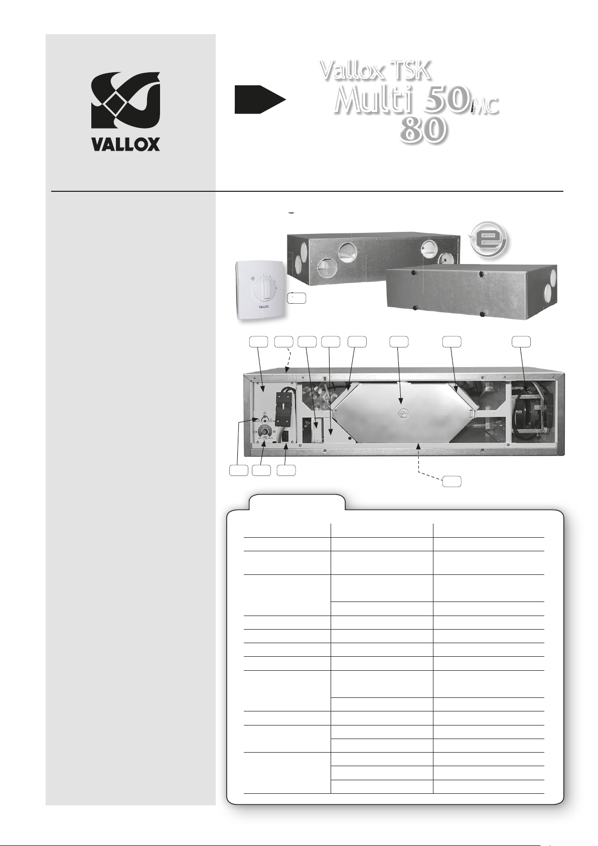
Low-energy ventilation unit
with heat recovery
Models
TSK Multi 50 MC 3603
TSK Multi 80 MC 3602
MC
© Vallox
1.09.399B EN
Updatet
26.1.2015
Valid from:
26.1.2015
1 Supply air fan
2 Extract air fan
3 Post-heating radiator, electric,
900 W (behind supply air heater)
4 Bypass duct heater, electric,
900 W (only TSK Multi 80 MC,
behind HR cell)
5 Heat recovery cell
6 Outdoor air fi lter F7
7 Outdoor air fi lter G4
8 Extract air fi lter G4
9 Automatic summer/winter damper
10 Safety switch
11 Adjustment of relationship between
supply and extract air
12 Adjustment of supply air
temperature and
summer/winter function
13 Speed selector switch (1-4)
(option)
Operating, maintenance and technical instructions
13
1
12 1011
TECHNICAL DATA
Electrical connection 230 V, 50 Hz, = 4.5 A 230 V, 50 Hz, = 8.8 A
Degree of protection
provided by enclosures
Integrated direct-current fan
Extract air 0.043 kW 0.32 A 57 dm
Supply air 0.043 kW 0.32 A 49 dm
Heat recovery Cross-counter fl ow cell, > 80% Cross-counter fl ow cell, > 80%
Heat recovery bypass Automatic Motorised damper
Electric post-heating unit 900 W, 3.9 A max 900 W, 3.9 A
Bypass duct heater - 900 W, 3.9 A
Filters
Supply air G4 + F7 G4 + F7
Extract air G4 G4
Weight 45.0 kg 58.5 kg
Ventilation power adjustment SC controller, 0-10 VDC SC controller, 0-10 VDC
Options SC controller SC controller
9 8 7563
4
VALLOX TSK MULTI 50 MC VALLOX TSK MULTI 80 MC
IP 34 IP 34
3
/s 100 Pa 0.071 kW 0.5 A 93 dm3/s 100 Pa
3
/s 100 Pa 0.071 kW 0.5 A 76 dm3/s 100 Pa
Remote monitoring control 0-10 VDC Remote monitoring control 0-10 VDC
SlimLine PTXP MC cooker hood SlimLine PTXP MC cooker hood
SlimLine PTXPA MC cooker hood SlimLine PTXPA MC cooker hood
2
Page 2
Vallox TSK
MCMC
Multi 50
80
MC
OPERATING INSTRUCTIONS
Fan speed adjustment
The fan speed of a Vallox ventilation unit can be controlled with a control switch (option), with
a separate cooker hood (option) or directly with a 0–11,4 V voltage signal.
Speeds 1, 2, 3 and 4 can be selected at the control switch.
1. Operation during absence. When the dwelling is empty, ventilation can be reduced
temporarily.
2–3. Normal operation. In normal operation, air has to be replaced once every two hours.
4. Boosted operation. Cooking, taking a sauna bath, washing, drying clothes, using
the toilet, having guests or a corresponding situation may cause a need for higher
ventilation than in normal operation.
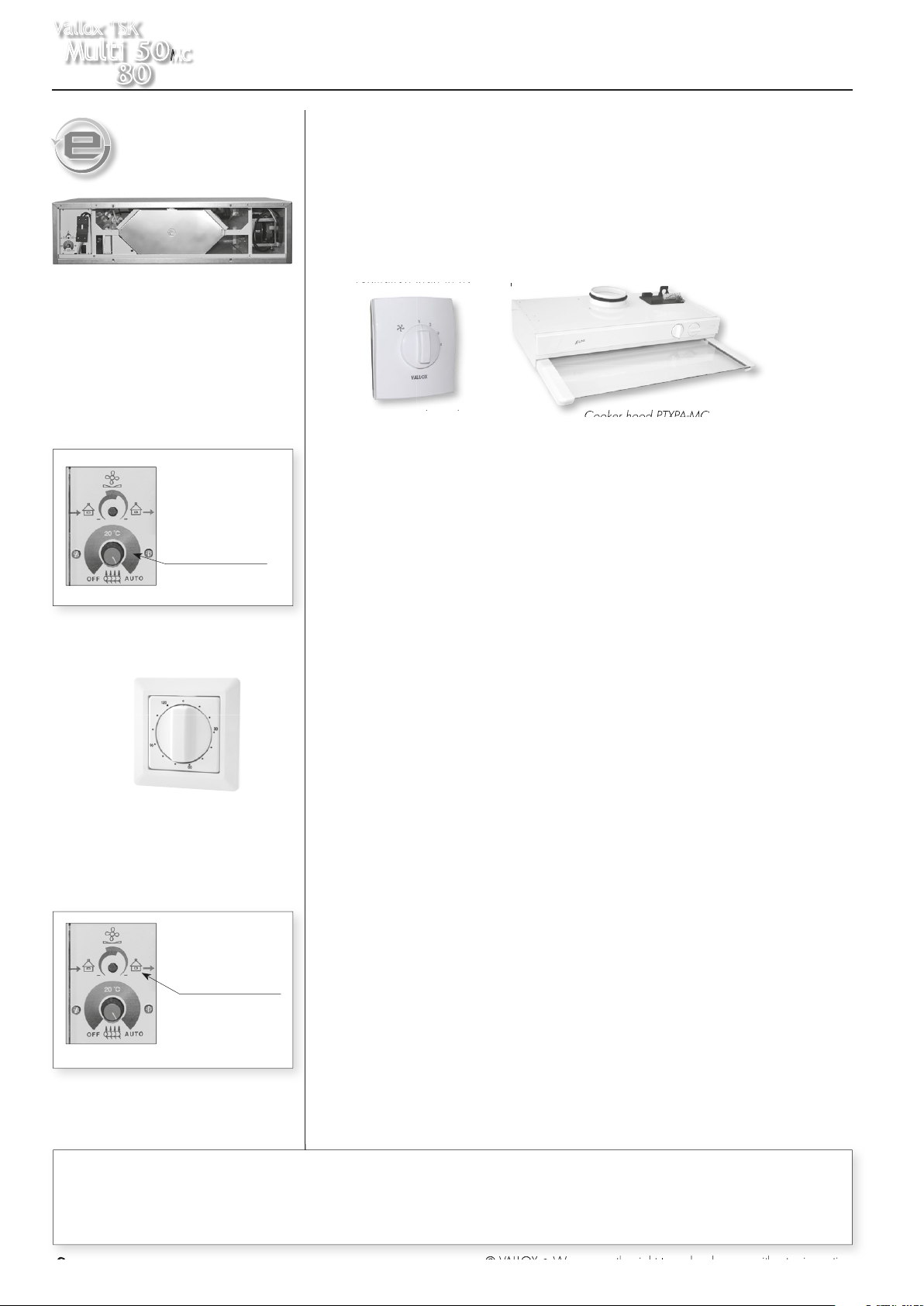
Adjustment of supply
air temperature
Fireplace switch, fl ush
mounting (option)
Supply and extract
air fl ow adjustment
potentiometer
Four-step control switch
Cooker hood PTXPA-MC
Adjustment of supply air temperature and summer/winter
function
The temperature of air coming to the dwelling can be adjusted between circa +10 °C and
+30 °C. The midpoint of the adjustment range is circa +20 °C. When supply air temperature
adjustment has been turned in the OFF position, post-heating is not active. This means that
summer function is activated for the ventilation unit. The unit has a motorised summer/winter
function. When the summer function is on, the heat recovery cell is bypassed as soon as
outdoor air temperature has risen above +14 °C. When outdoor air temperature goes below
+12 °C, the unit starts to recover heat. When supply air temperature adjustment is in the
AUTO position, automatic function is activated for the unit. In this case, the setpoint for postheating is +17 °C and the heat recovery cell is bypassed automatically according to outdoor
temperatures as indicated above. When the unit bypasses the heat recovery cell, in which
case summer function is activated, post-heating is off.
Fireplace switch function
It is possible to connect a timer-operated switch to the unit. The switch stops the extract air fan
during the time when the fi replace is heated. NOTE! The starting of the extract air fan may
weaken draught in the fi replace! In winter, this situation may disturb the winter function of the
unit. The situation will normalise in a while, after the fi replace function stops.
Winter function of ventilation unit
A threshold value has been set at the factory for the freezing of the heat recovery cell. When
the threshold is exceeded, the ventilation unit starts to melt the heat recovery cell by guiding
outdoor air fl ow to bypass the heat recovery cell.
A normal melting period takes from 15 to 45 minutes depending on the extent of ice on
the heat recovery cell and on the amount of extract air fl ow. The unit has been optimised to
operate on the factory settings in normal operation in dwellings and detached houses. The
winter function parameters can be adjusted for extreme conditions, such as a swimming bath,
but even then it is advisable to contact Vallox Maintenance.
Adjustment of relationship between supply and extract air
This feature may be useful when adjusting air fl ows at the valves during mounting. After the
valves have been adjusted, a user does not need, and must not, touch the adjustment. When
needed, supply or extract air fl ow can be reduced at the potentiometer.
When the potentiometer is approximately halfway, supply and extract air fl ow have not been
reduced. Turning the potentiometer anticlockwise reduces air fl ow on the supply side, and
turning it clockwise reduces air fl ow on the extract side.
Maintenance reminder
The unit reminds of the need for maintenance every six months if an indicator (not standard)
has been connected to the connectors of the fault signal relay. The indicator then blinks at
one-second intervals. The maintenance reminder is reset when the door of the ventilation unit
is opened. See the maintenance instructions for information on the necessary maintenance
activities.
This appliance can be used by children aged from 8 years and above and persons with reduced physical, sensory or mental capabilities or lack
of experience and knowledge if they have been given supervision or instruction concerning use of the appliance in a safe way and understand
Children shall not play with the appliance.
Cleaning and user maintenance shall not be made by children without supervision.
2
the hazards involved.
© VALLOX • We reserve the right to make changes without prior notice.
What the units include can vary depending on the sales area.
Page 3
MAINTENANCE INSTRUCTIONS
Troubleshooting
When a fault described in the table appears, the unit indicates of
the fault with a fault signal relay, indicator light and LED on the circuit
board. The number of blinks reveals the fault in question
Led
Problem Repair
blinks
Supply air sensor after the HR cell is faulty Check the sensor and conductors, replace if needed
1
Extract air sensor is faulty Check the sensor and conductors, replace if needed
2
Supply air sensor is faulty Check the sensor and conductors, replace if needed
3
Exhaust air sensor is faulty Check the sensor and conductors, replace if needed
4
Outdoor air sensor is faulty Check the sensor and conductors, replace if needed
5
Supply air fan has stopped Check the wiring of the fan, replace the fan if needed
6
Extract air fan has stopped Check the wiring of the fan, replace the fan if needed
7
EEPROM faulty Replace the circuit board of the unit with a new one
8
Vallox TSK
Multi 50
80
MC
MAINTENANCE
T
Before starting maintenance
operations
When you open the VALLOX TSK Multi 50/80
MC unit, the safety switch of the door (T) turns
power off from the unit. In spite of that, always
disconnect the plug of the VALLOX TSK Multi
50/80 MC unit before starting maintenance
operations.
Filters
When the maintenance reminder gives an alarm, the cleanliness of
the fi lters must be checked. Outdoor air is fi ltered in the unit with two
kinds of fi lters. A coarse fi lter (A) fi lters off insects, heavy pollen and
other dust. An F7 class fi ne fi lter (B) fi lters off fi ne dust invisible to the
eye. Extract air is fi ltered with a coarse fi lter (C).
By using original Vallox fi lters you ensure good operation of the
ventilation unit and the best fi ltering result. The replacement interval
of fi lters depends on dust content in ambient air. It is recommended to
replace fans in spring and autumn, but at least once a year.
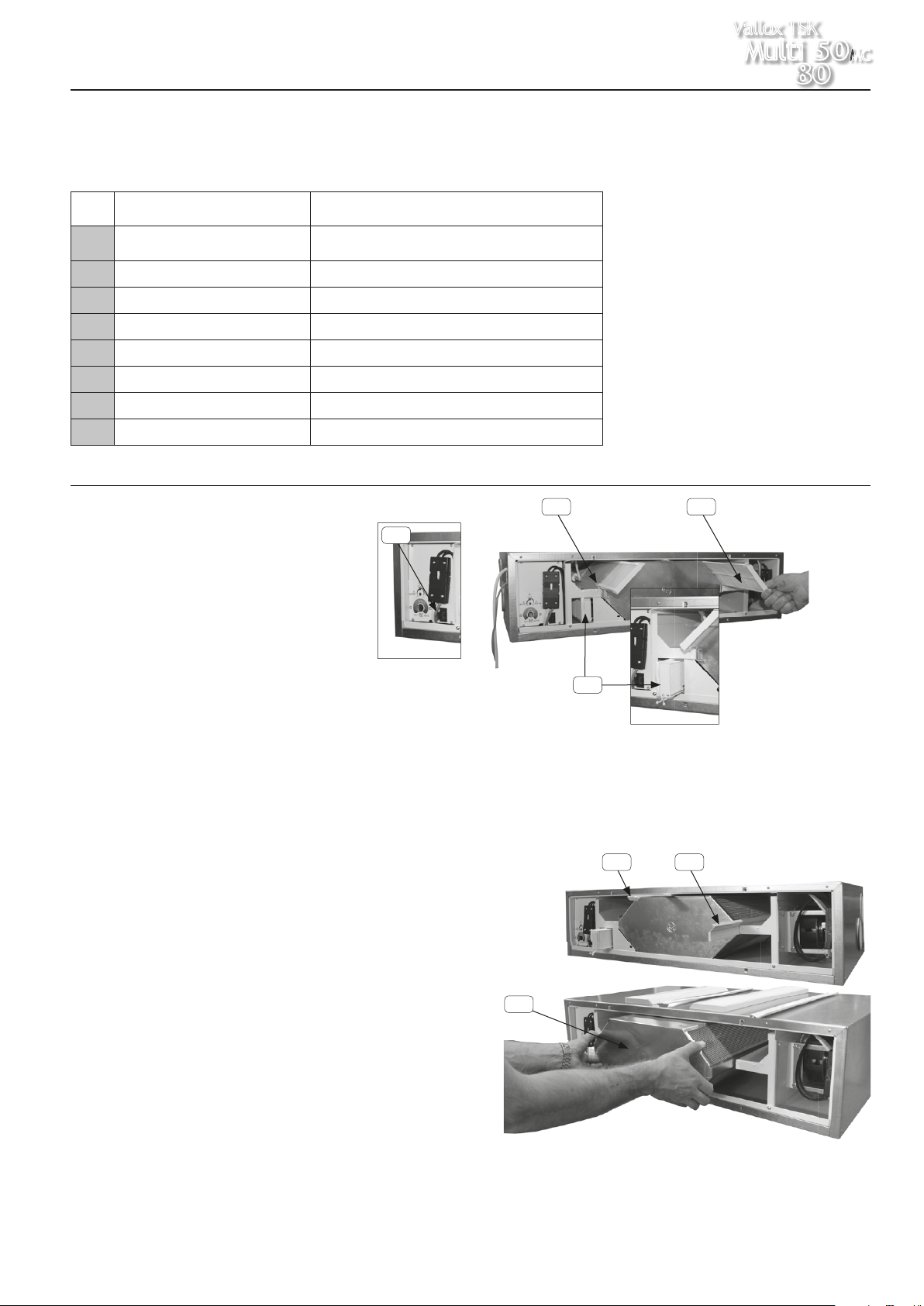
Heat recovery cell
When you replace the fi lters, you are also advised to check the
cleanliness of the heat recovery (HR) cell (D) at about two-year
intervals.
The G4 fi lters and their supports, the sealing ledge (E) above the HR
cell and the side sealing ledge (F) must be pulled off before the cell
can be detached. When the sealing ledge has been removed, the
HR cell can be pulled out of the unit.
Note! The laminas of the HR cell are very thin and get easily
damaged. The correct way to remove the HR cell is to put your
hands behind the HR cell and slowly pull it off. If the HR cell is dirty,
wash it by immersing it in a solution of water with washing-up liquid.
Rinse the HR cell clean with a jet of water. When water has drained
from between the laminas, you can push the HR cell back in place.
Finally, push the sealing ledges and fi lters in place.
C A
B
VALLOX TSK Multi 50/80 MC fi lters and heat recovery cell
The units are available as right- and left-handed models. In a right-handed
(model R) model, outdoor air comes to the unit from the right side of the
centre line, as shown in the instructions. In a left-handed (model L) unit, outdoor comes from the left side of the unit. The fi lters, summer/winter damper
and heating radiator also change places correspondingly.
E F
D
Detaching of HR cell
Pull the coarse fi lters and their frames out of the unit. Also remove the fi ne
fi lter if it has been used. You can then pull out the sealing ledges situated
on top and on the sides of the HR cell. When the sealing ledges have been
removed, the HR cell can be pulled out of the unit. Note! The laminas of the
HR cell are very thin and get easily damaged.
© VALLOX • We reserve the right to make changes without prior notice.
What the units include can vary depending on the sales area.
3
Page 4
Vallox TSK
Multi 50
80
MC
MAINTENANCE INSTRUCTIONS
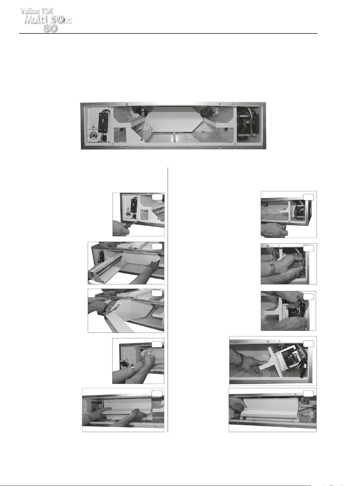
Fans
Check the cleanliness of the fans when carrying out maintenance for
the fi lter and the heat recovery cell. Clean the fans if needed. The
fans can be removed from the unit for cleaning. The fan blades can
be cleaned with compressed air or with a brush. Do not remove or
move the balancing pieces on the fan blade.
Unit with HR cell and fi lters removed
Detaching of supply air fan, right-handed unit
(When detaching the supply air fan of a left-hand unit,
reverse the instructions.)
1
1. Unfasten the fi xing screw of the fan
housing.
Detaching of supply and extract air fan
Before detaching the supply and extract air fans, you have to remove
the fi lters and the heat recovery cell of the unit as described earlier.
The detaching and remounting of the fan housings and bypass duct
must be done carefully according to the following instructions in order
to avoid damage. Because the unit is small in size, there is not much
room for maintenance.
Detaching of extract air fan, right-handed unit
(When detaching the supply air fan of a left-hand unit, reverse the
instructions)
1
1. IUnfasten the fi xing screw
of the fan housing.
2. Pull the bypass duct/fi lter
stand bundle out and turn
it to the right.
3. Unfasten the wire of the
bypass damper motor.
4. Tilt the supply air fan to the right and
take the connectors out of way.
5. Turn the fan by 90° and
pull it out from the unit,
tilting it forwards.
2
2. Detach the connector
bundle from the wall.
3. Detach the connectors from
3
4
5 5
each other.
4. Tilt the fan to the
left and turn by
90°.
5. Pull the fan out,
tilting it forwards.
2
3
4
The mounting of the fan housings is carried out in the opposite order.
4
© VALLOX • We reserve the right to make changes without prior notice.
What the units include can vary depending on the sales area.
Page 5

MAINTENANCE INSTRUCTIONS
Condensing water
During the heating season, humidity of extract air condenses into
condensing water. Water formation may be abundant in new
buildings or if ventilation is low compared to the humidity build-up
caused by the residents.
Condensing water needs to fl ow out from the ventilation unit without
hindrance. In carrying out maintenance, for instance in autumn
before the beginning of the heating season, make sure that the
condensing water outlet (L) in the bottom tank is not clogged. You
can check it by pouring a little water in the tank. Clean if needed.
Do not let water fl ow into electrical devices. The unit comes with
a condensing outlet (in the fi gure) equipped with an airlock and
an outlet without airlock that takes less space. If you use the outlet
without airlock, you have to mount an airlock somewhere between
the discharge pipes (the accessory bag contains the parts needed).
An airlock guarantees the removal of condensing water and
silencing of any sounds.
Location of condensing water
outlet from side
Vallox TSK
Multi 50
80
Location of condensing water outlet
from behind
MC
© VALLOX • We reserve the right to make changes without prior notice.
What the units include can vary depending on the sales area.
5
Page 6

Vallox TSK
Multi 50
MC
80
Measuring points
Measuring points after the
connection outlet. Fan curves
indicate the total pressure
available for duct losses.
Supply air
Extract air
TECHNICAL DATA
Performance TSK Multi 50 MC
Air volumes Vallox TSK Multi 50 Supply air (F7 + G4), Extract air (G4)
300
E = Extract air fan
S = Supply air fan
ED and SD are examples of pressure
losses in supply and extract ducts.
SFP (Specifi c Fan Power) recommended value <2.5 (kW m3/s)
Input power (total) (W)
SFP =
Air fl ow (max) (dm
3
/s)
SEEN FROM ABOVE
Left
side
Input power of the unit
Fan control voltage
with SC controller
(V)
Input power of
the unit
(W)
3 11
4 15
5 20
6 26
7 37
8 49
9 65
10 87
11,4 108
Sound
values
Adjustment position
Air fl ow dm3/s
Medium
frequency
of the
octave
band Hz
L
L
11,4 V 10,0 V 9,0 V 8,0 V 7,0 V 6,0 V 5,0 V 4,0 V 3,0 V 11,4 V 10,0 V 9,0 V 8,0 V 7,0 V 6,0 V 5,0 V 4,0 V 3,0 V
54,6 50,4 43,9 38,7 31,3 25,1 18,8 13,8 8,1 62,8 56,9 50,3 45,0 37,9 32,1 26,2 19,1 13,7
57,6 57,4 54,1 52,8 50,2 47,3 44,9 40,7 42,3 51,0 50,0 47,6 45,5 43,4 *38,2 *34,0 *31,6 *30,3
63
60,4 59,3 57,3 55,6 53,7 50,0 51,1 47,8 40,5 57,8 57,0 54,5 51,9 49,2 48,0 44,7 44,1 40,4
125
64,0 62,3 61,0 59,9 58,5 55,1 51,2 45,9 34,9 55,3 53,9 52,7 52,1 48,6 47,9 43,5 37,6 28,7
250
66,2 64,3 61,8 60,8 55,2 50,0 45,5 39,5 30,1 51,0 50,2 48,3 49,4 40,8 36,2 30,8 *25,3 *17,6
500
63,2 61,5 59,6 56,6 51, 47,5 42,3 35,5 *24,0 51,1 49,3 46,5 44,1 39,1 36,1 31,6 *25,4 *16,8
1000
58,8 56,9 54,3 51,3 47,4 41,9 34,4 *23,9 *17,8 40,1 38,4 36,8 35,3 29,9 *27,7 *21,3 *13,9 *12,2
2000
53,6 51,4 48,1 43,9 38,0 *29,6 *23,1 *20,6 *18,6 33,0 31,1 29,5 *26,5 *19,9 *18,4 *17,6 *17,6 *17,5
4000
36,5 33,4 *29,6 *26,5 *24,3 *23,3 *23,1 *23,1 *23,2 *23,5 *23,2 *23,1 *23,2 *22,9 *22,9 *22,9 *22,9 *22,9
8000
L
,dB
70,6 68,9 66,8 65,2 62,0 58,1 55,4 50,9 45,2 61,3 60,2 58,1 56,7 53,0 51,5 47,6 45,3 *41,2
W
, dB(A)
WA
67,5 65,6 63,3 61,1 57,0 52,3 47,6 41,5 32,5 54,1 52,7 50,6 49,7 44,5 42,7 38,0 *33,5 *28,9
Sound pressure level coming from the unit through the envelope in the rooms where the unit has been installed
11,4 V 10,0 V 9,0 V 8,0 V 7,0 V 6,0 V 5,0 V 4,0 V 3,0 V
54,0 / 61,4 49,3 / 55,8 43,9 / 50,1 38,1 / 44,0 31,5 / 37,3 25,1 / 30,9 19,4 / 25,1 13,4 /18,6
, dB (A) 49,2 47,7 45,6 42,9 39,3 35,6 32,1 *27,0 *24,4
pA
250
Right
side
200
150
100
50
Pressure loss in ducts. Total pressure (Pa)
E 3,0 V
S 3,0 V
S 4,0 V
E 4,0 V
S 5,0 V
E 5,0 V
S 6,0 V
E 6,0 V
0
Sound power level in supply air duct (one duct)
ADJUSTMENT POSITION/AIR FLOW dm
by octave band L
, dB
W
3
/s ADJUSTMENT POSITION/AIR FLOW dm3/s
ADJUSTMENT POSITION/AIR FLOWS (supply/extract)
S 9,0 V
E 8,0 V
S 8,0 V
E 7,0 V
S 7,0 V
2
sound absorption)
(10m
S 11,4 V
E 10,0 V
S 10,0 V
E 9,0 V
Volume fl ow rate (dm
E 11,4 V
SFP <2.0 kW/m
3/
s
ED
SFP <1.5 kW/m
W
SD
3/
s
, dB
SFP <1.0 kW/m
3/
s
3
/s)
Sound power level in extract air duct (one duct)
by octave band L
8,0 / 13,1
*The background noise requirements of standard ISO 3741:2010 have not been met
6
© VALLOX • We reserve the right to make changes without prior notice.
What the units include can vary depending on the sales area.
Page 7

TECHNICAL DATA
Performance TSK Multi 80 MC
Vallox TSK
Multi 50
80
MC
Measuring points
Measuring points after the
connection outlet. Fan curves
indicate the total pressure
available for duct losses.
Supply air
Extract air
SEEN FROM ABOVE
Left
side
Input power of the unit
Fan control voltage
with SC controller
(V)
Input power of
the unit
(W)
3 12
4 17
5 25
6 34
7 47
8 68
9 95
10 125
11,3 165
Right
side
Air volumes Vallox TSK Multi 80 Supply air (F7 + G4), Extract air (G4)
E = Extract air fan
S = Supply air fan
ED and SD are examples of pressure
losses in supply and extract ducts.
SFP (Specifi c Fan Power) recommended value <2.5 (kW m3/s)
Input power (total) (W)
SFP =
Air fl ow (max) (dm
3
/s)
350
300
250
200
S 8,0 V
E 10,0 V
S 10,0 V
E 9,0 V
S 9,0 V
E 8,0 V
S 11,3 V
E 11,3 V
SFP <2.0 kW/m
3/
s
ED
150
100
Pressure loss in ducts. Total pressure (Pa)
50
E 3,0 V
S 3,0 V
E 4,0 V
S 4,0 V
0
E 5,0 V
S 5,0 V
S 6,0 V
E 6,0 V
S 7,0 V
E 7,0 V
SFP <1.0 kW/m
SD
SFP <1.5 kW/m
3/
s
3/
s
0 10 20 30 40 50 60 70 80 90 100 110
Volume fl ow rate (dm
3
/s)
Sound
values
Adjustment position
Air fl ow dm3/s
Medium
frequency
of the
octave
band Hz
L
, dB(A)
WA
, dB (A) 53,5 51,2 49,5 45,9 42,0 37,4 34,4 *28,9 *24,7
L
pA
Sound power level in supply air duct (one duct)
ADJUSTMENT POSITION/AIR FLOW dm
by octave band L
, dB
W
3
/s ADJUSTMENT POSITION/AIR FLOW dm3/s
Sound power level in extract air duct (one duct)
by octave band L
, dB
W
11,3 V 10,0 V 9,0 V 8,0 V 7,0 V 6,0 V 5,0 V 4,0 V 3,0 V 11,3 V 10,0 V 9,0 V 8,0 V 7,0 V 6,0 V 5,0 V 4,0 V 3,0 V
83,8 75,2 65,7 57,7 47,9 39,6 31,6 23,1 15,6 101,0 92,2 81,3 71,2 59,3 50,3 43,3 33,1 22,3
60,4 60,4 57,4 56,0 54,3 52,4 55,8 43,3 43,2 55,6 55,0 57,7 54,5 48,5 47,3 48,4 39,8 *38,9
63
64,5 61,9 60,4 58,5 56,9 54,6 52,4 46,1 39,1 60,1 58,3 56,8 53,7 50,9 48,3 48,0 41,6 33,9
125
71,9 72,0 69,5 68,0 60,3 56,6 50,9 46,0 38,3 59,1 58,2 56,9 55,3 50,3 46,9 42,9 36,7 30,3
250
73,0 66,8 63,2 59,9 56,3 51,8 47,4 40,9 33,1 55,2 52,3 48,9 45,9 42,9 37,5 34,3 27,1 *21,8
500
66,0 62,9 59,7 56,5 51,8 47,1 42,5 36,2 *27,9 53,1 49,9 47,5 44,1 40,0 35,7 32,1 *25,5 *19,8
1000
62,0 59,3 56,2 53,0 48,9 43,6 38,3 30,1 *19,7 42,3 39,8 37,0 33,6 29,7 25,8 *22,3 *16,4 *13,9
2000
52,5 49,6 46,1 42,2 37,2 31,5 *25,8 *20,0 *17,9 29,4 *26,7 *23,9 *20,7 *18,8 *18,0 *17,8 *17,7 *18,0
4000
38,5 34,9 30,8 *27,3 *24,4 *23,2 *23,0 *23,0 *22,9 *23,5 *23,2 *23,1 *23,1 *23,0 *23,0 *23,0 *23,0 *23,0
8000
L
,dB
76,6 74,2 71,5 69,6 64,0 60,6 58,8 50,8 45,9 64,4 62,9 62,3 59,6 55,2 52,6 52,0 44,7 *40,7
W
72,2 69,1 66,1 63,2 57,9 53,4 48,8 42,6 *35,0 57,0 54,8 52,7 49,8 45,7 41,6 38,9 *32,7 *28,1
Sound pressure level coming from the unit through the envelope in the rooms where the unit has been installed
2
sound absorption)
(10m
ADJUSTMENT POSITION/AIR FLOWS (supply/extract)
11,3 V 10,0 V 9,0 V 8,0 V 7,0 V 6,0 V 5,0 V 4,0 V 3,0 V
84,0 / 88,1 74,8 / 79,2 66,1 / 70,4 57,0 / 61,7 47,4 / 52,1 39,3 / 43,1 32,3 / 36,8 23,4 / 27,8
*The background noise requirements of standard ISO 3741:2010 have not been met
15,1 / 19,5
© VALLOX • We reserve the right to make changes without prior notice.
What the units include can vary depending on the sales area.
7
Page 8

Vallox TSK
Multi 50
80
Electrical
connection
MC
S Supply air fan
E Extract air fan
TK Safety switch
R1 Bypass duct heater (80 MC, behind HR cell)
R2 Post-heating radiator
M Damper motor
FS Fireplace switch (option)
OK Voltage switch (in the cooker hood)
VA Light switch (in the cooker hood)
Wiring:
BK black
BN brown
BU blue
GN green
GY grey
E
RD = 7
WT = 8
WT white
YE/GN yellow/green
RD red
YE = 16
BU = 15
BK = 1
BN = 2
YE/GN = 9
BU = 1
BN = 2
YEGN = 9
951153 / 951159:
BN = 7
WT = 8
951150 / 951152
TECHNICAL DATA
951153
951152
YE = 16
GN = 15
R1
130°C
T1
T2
90°C
DIP switch Up Down
1. Post-heating Electric VKL
2. Additional heating Electric MLV
3. Unit type Bypass Supply fan stopped
LINE: Phase voltage
NEUTRAL: Zero voltage
SLI: Phase voltage to safety switch
SNI: Zero voltage to safety switch
SLO: Phase voltage to circuit board from safety switch
SNO: Zero voltage to circuit board from safety switch
SFL: Phase voltage to supply air fan
SFN: Zero voltage to supply air fan
EFL: Phase voltage to extract air fan
EFN: Zero voltage to extract air fan
FSO: Input to fireplace switch
FSI: Fireplace switch output
AHL: Phase voltage to post-heating
AHN: Zero voltage to post-heating
PHL: Phase voltage to additional heater
PHN: Zero voltage to additional heater
BL: Damper motor phase A
BL1: Damper motor phase B
BN: Damper motor zero
E/I: Fault signal relay input
E/O: Fault signal relay output
951154
951155
4
BK
WT
6
7
5
8
4
8. Supply fan PWM
7. Supply fan Tako
6. GND / -
5. Extract fan PWM
4. Extract fan Tako
SLO, BK
SNO. BK
SFL, BN
SFN, BU
EFL, BN
1
2
3
Extract air NTC ”1”
2
3
1
3. GND / -
2. 11.2 Vdc /+
1. Control signal S
EFN, BU
FSO
FSI
1
AHL, BN
Outdoor air NTC “2”
2
Adjustment of freezing level
AHN, BU
PHL, BN
1 = N
3 =
2 = L
M
GNYEWTGNYE
9
Programming
connector
9. GND / -
LINE, BN
NEUTRAL, BU
SLI, BK
SNI, BK
4. Winter function Normal Wet
Supply air to the dwelling NTC ”3”
PHN, BU
PWM level adjustment
Exhaust air NTC ”4”
Supply air from the cell NTC ”5”
345
3 4
1 2
DIP switch
Adjustment of post-heating
Fault signal relay
LED
BL1, 3
BL, 2
BN, 1
E/I
E/O
BK
4
TK
4 x 951107
T1
130°C
S
T2
90°C
R2
951150
951166
+
4
3
2
1
External controller
or cooker hood
8
© VALLOX • We reserve the right to make changes without prior notice.
What the units include can vary depending on the sales area.
951159
951123
951129
LED
S
3461600
230V 50Hz
7024000
Page 9

MOUNTING INSTRUCTIONS
Vallox TSK
Multi 50
80
MC
Mounting location
VALLOX TSK Multi 50/80 MC has to be
mounted in a place where temperature does
not go below +10 °C. Without protective
enclosure, the unit must be located in a place
with no acoustic disturbance: storeroom,
utility room, suspended ceiling etc.
Important!
The outdoor air duct to the unit and the
exhaust air duct out must be insulated with
closed cell insulation for the whole length.
Dimensions and duct outlets
DIMENSION VALLOX TSK
MULTI 50 mm
A 900 1026
B 547 626
C 236 293
D 100 (female) 125 (female)
E 87 110
F 197 254
G 86 110
H 161 200
I 161 200
J 86 96
K 96 96
L 206 231
M 498 624
VALLOX TSK
MULTI 80 mm
Seen from
the right
G
Fastening
VALLOX TSK Multi 50/80 MC is mounted
normally to a ceiling with four fastening hooks
delivered with the unit. When fastening, take
into account that the unit weighs 45 kg.
Important!
Mount the unit horizontally level to make
sure that the condensing water gathering
in the bottom tank runs into the condensing
outlet.
A
4
H
B
4
1
C
I
Right side
1
4
4
J
K
L
Seen from above
1
1
Seen from behind
Condensing water
The delivery includes a water seal. By
connecting a pipe to the water seal the
water condensing from extract air can be
led to a fl oor drain (not directly to the drain).
The pipe must not rise after the water seal.
For further instructions on the mounting of
the water seal and outlet, see the accessory
bag.
Seen from
the left
ØD
2
Left side
3
2
3
3
2
J
K
L
2
3
Model R:
1. Outdoor air to unit
2. Supply air to rooms
3. Extract air to unit
4. Exhaust air out
I
Model L:
1. Extract air to unit
2. Exhaust air out
3. Outdoor air to unit
4. Supply air to rooms
F
E
DIMENSION VALLOX TSK
MULTI 50 mm
A 431 519
B 91 91
C 16 16
D 548 626
E 530 600
F 236 293
G 935 1060
H 900 1026
VALLOX TSK
MULTI 80 mm
SPACE FOR MAINTENANCE
Plug cord and cord
for SC speed switch
F
E
SPACE FOR MAINTENANCE
B
G
H
ALITOTLOUH
D
A
Water seal
Water outlet
(alternative)
C
43
61
Space required
for mounting
27
47
54
© VALLOX • We reserve the right to make changes without prior notice.
What the units include can vary depending on the sales area.
9
Page 10

Vallox TSK
Multi 50
MC
80
Exploded view and parts list
VALLOX TSK MULTI MC 50/80
39
40
6
4
5
29
23
27
22
2b
7
20
21
2
19
17
3
18
LIST OF SPARE PARTS
28
1
32
37
35
4
33
36
34
8
13
12
14
15
10
9
41
42
26
16
30
31
11
25
24
38
No. Part Code
1 Body TSK Multi 50 SC BP / 50 MC / 80 SC BP / 80 MC
2 Door assembly (incl. 2b door switch button) (50 MC/SC BP) .............................................................................................3473500
2 Door assembly (incl. 2b door switch button) (80 MC/SC BP) .............................................................................................3483000
3 Heat exchanger, counter-fl ow cell GS1 8/400 (50 MC/SC BP) ..........................................................................................933120
3 Heat exchanger, counter-fl ow cell GS 25/450 (80 MC/SC BP) ..........................................................................................933130
4 Fan assembly (50 MC/SC BP) .....................................................................................................................................3473400
4 Fan assembly (80 MC/SC BP) .....................................................................................................................................3482900
5 Fan motor 43 W (50 MC/SC BP) R3G133-AE07-02EC ....................................................................................................935385
5 Fan motor 71 W (80 MC/SC BP) R3G190-AB07-02 EC ................................................................................................... 935375
6 Fan mounting plate ..................................................................................................................................................... 3335110
7 Fan fastening angle ....................................................................................................................................................1088410
8 Fan housing (metal parts: inlet cone, partition and insulation) (50 MC/SC BP) ....................................... 3463100, 3463200, 3463300
8 Fan housing (metal parts: inlet cone, partition and insulation) (80 MC/SC BP) ....................................... 3387410, 3318210, 3478900
9 Bypass duct assembly (50 MC/SC BP R)........................................................................................................................3432700
9 Bypass duct assembly (50 MC/SC BP L) ........................................................................................................................ 3432701
9 Bypass duct assembly (80 MC/SC BP R)........................................................................................................................3479500
9 Bypass duct assembly (80 MC/SC BP L) ........................................................................................................................ 3479600
10 Body of bypass duct and F7 fi lter support (50 MC/SC BP) ................................................................3433111, 3425310, 3451901
10 Body of bypass duct and F7 fi lter support (80 MC/SC BP) ................................................................3479700, 3479800, 3480100
11 Cell damper (50 MC/SC BP) ......................................................................................................................................3433000
11 Cell damper (80 MC/SC BP) ......................................................................................................................................3480000
12 Bypass duct damper (50 MC/SC BP) ............................................................................................................................ 3432800
12 Bypass duct damper (80 MC/SC BP) ............................................................................................................................ 3479900
13 Damper motor CM230-R (R units) .................................................................................................................................... 930621
13 Damper motor CM230-L (L units) ..................................................................................................................................... 930620
14 Damper motor arm (50 MC/SC BP) .............................................................................................................................. 3383320
14 Damper motor arm (80 MC/SC BP) .............................................................................................................................. 3480300
10
© VALLOX • We reserve the right to make changes without prior notice.
What the units include can vary depending on the sales area.
Page 11

Vallox TSK
Multi 50
LIST OF SPARE PARTS
No. Part Code
15 Retaining bracket for arm ............................................................................................................................................. 3458100
16 Bottom of connection box (50 MC/SC BP) ..................................................................................................................... 3444800
16 Bottom of connection box (80 MC/SC BP) ..................................................................................................................... 3444810
17 Cover of connection box (50 MC/SC BP) ...................................................................................................................... 3444900
17 Cover of connection box (80 MC/SC BP) ...................................................................................................................... 3444910
18 Ground terminal ........................................................................................................................................................... 950432
19 Cable clamp ............................................................................................................................................................... 952130
20 MC circuit board .........................................................................................................................................................949035
21 MC potentiometer .......................................................................................................................................................951110
22 Safety switch Cherry/ Dong Hai .....................................................................................................................................948370
23 MC potentiometer knob ................................................................................................................................................. 948435
24 HR side sealing ledge (50 MC/SC BP) .......................................................................................................................... 3356300
24 HR side sealing ledge (80 MC/SC BP) .......................................................................................................................... 3352600
25 HR upper sealing ledge (50 MC/SC BP)........................................................................................................................3463400
25 HR upper sealing ledge (80 MC/SC BP)........................................................................................................................3488700
26 G4 fi lter stand 500 mm (supply air) (50 MC/SC BP) ........................................................................................................3356400
26 G4 fi lter stand 580 mm (supply air) (80 MC/SC BP) ........................................................................................................3352700
27 G4 fi lter stand 400 mm (extract air) (50 MC/SC BP) ........................................................................................................3382800
27 G4 fi lter stand 450 mm (extract air) (80 MC/SC BP) ........................................................................................................3368500
28 G4 fi lter (supply air) (50 MC/SC BP) ...............................................................................................................................978036
28 G4 fi lter (supply air) (80 MC/SC BP) .............................................................................................................................3326700
29 G4 fi lter (extract air) (50 MC/SC BP) ..............................................................................................................................978035
29 G4 fi lter (extract air) (80 MC/SC BP) ............................................................................................................................3379700
30 F7 fi lter (50 MC/SC BP) ...............................................................................................................................................978136
30 F7 fi lter (80 MC/SC BP) ...............................................................................................................................................978135
31 F7 fi lter puller (50 MC/SC BP) .....................................................................................................................................3452100
31 F7 fi lter puller (80 MC/SC BP) .....................................................................................................................................3480200
32 Plug (50 MC/SC BP) ....................................................................................................................................................990630
32 Plug (80 MC/SC BP) ....................................................................................................................................................990640
33 Cover plate 100 mm (50 MC/SC BP) ........................................................................................................................... 3363500
33 Cover plate 125 mm (80 MC/SC BP) ........................................................................................................................... 3363600
34 Water seal ................................................................................................................................................................3212200
35 Condensing water outlet .............................................................................................................................................. 3477000
36 Pipe connector cover of water seal ................................................................................................................................3482600
37 Ceiling mounting part (in mounting accessory bag 3361500) ............................................................................................ 3358500
38 Knurled-head screw ......................................................................................................................................................990698
39 Post-heating radiator (R units) ...........................................................................................................................................942210
39 Post-heating radiator (L units) ........................................................................................................................................... 942211
40 Post-heating radiator holder .......................................................................................................................................... 3452000
41 Bypass duct radiator (80 MC R units) ............................................................................................................................... 942210
41 Bypass duct radiator (80 MC L units) ................................................................................................................................942211
42 Front resistor bracket ...................................................................................................................................................3429500
80
MC
© VALLOX • We reserve the right to make changes without prior notice.
What the units include can vary depending on the sales area.
11
Page 12

Vallox TSK
Multi 50
80
MC
12
www.vallox.com
© VALLOX • We reserve the right to make changes without prior notice.
1.09.399bE/26.1.2015/PDF
What the units include can vary depending on the sales area.
 Loading...