

Page 1
DIGIT SED
ELECTRONIC CONTROLLER
WITH LCD DISPLAY
• 1.09.61E
• 27.5.2008
• CODE B 3500 SE
© VALLOX
VKL
INSTRUCTIONS FOR USE AND MAINTENANCE
MODELS:
VALLOX DIGIT SE
VALLOX DIGIT SE VKL
© VALLOX • We reserve the right to make changes without prior notification.
Page 2
VALLOX DIGIT SE has been initially adjusted
for normal circumstances in your home. Ventilation adjustment is needed mainly in the
following circumstances:
1. THREE QUESTIONS ABOUT VENTILATION
1.1. Why are rooms ventilated? ............................................................ p. 3
1.2. What are the characteristics of adequate ventilation? ........................ p. 3
1.3. How much ventilation is needed? .................................................... p. 3
2. INSTRUCTIONS FOR USE: VALLOX DIGIT SE
2.1. Taking into use ............................................................................. p. 4
2.2. Ventilation control .......................................................................... p. 4
2.3. Ventilation control with control panel................................................ p. 4
2.4. Ventilation control with CO2 sensor ................................................. p. 5
2.5. Ventilation control with humidity sensor ............................................ p. 5
2.6. Ventilation control with voltage or current signals............................... p. 5
2.7. Ventilation control with remote monitoring system .............................. p. 5
2.8. Post-heating .................................................................................. p. 5
2.9. Supply air constant temperature control ........................................... p.
2.10. Supply air cascade control ............................................................. p. 6
2.11. Heat recovery bypass .................................................................... p. 6
2.12. Heat recovery cell defrosting function............................................... p. 6
2.13. Maintenance reminder ................................................................... p. 7
2.14. Filter guard function....................................................................... p. 7
2.15. Anti-freezing of the water circulated post-heating radiator................... p. 7
2.16. Fireplace switch / boosting function................................................. p. 7
2.17. Fault signalling relay...................................................................... p. 7
2.18. Air filtration .................................................................................. p. 7
3. CONTROL PANEL
3.1. Instructions for use ......................................................................... p. 8
3.2. Operating menu............................................................................ p. 8
3.3. Settings menu................................................................................ p. 9
3.4. Week clock control ........................................................................p. 11
3.4. Factory settings .............................................................................p. 12
4. INSTRUCTIONS FOR MAINTENANCE
4.1. Filters ...........................................................................................p. 13
4.2. Fans and post-heating radiator........................................................p. 14
4.3. Filter guard...................................................................................p. 14
4.4. Condensing water .........................................................................p. 13
5. TROUBLESHOOTING...................................................................................p. 16
VALLOX DIGIT SE/SE VKL
TABLE OF CONTENTS
2
2
VALLOX DIGIT SE models
Code: B3500 SE
VALLOX DIGIT SE
• Post-heating radiator: electric radiator 1000 W
ALLOX DIGIT SE VKL
• Post-heating radiator: water radiator
• Letter L or R after the name of the unit indicates whether the unit
is left- or right-handed.
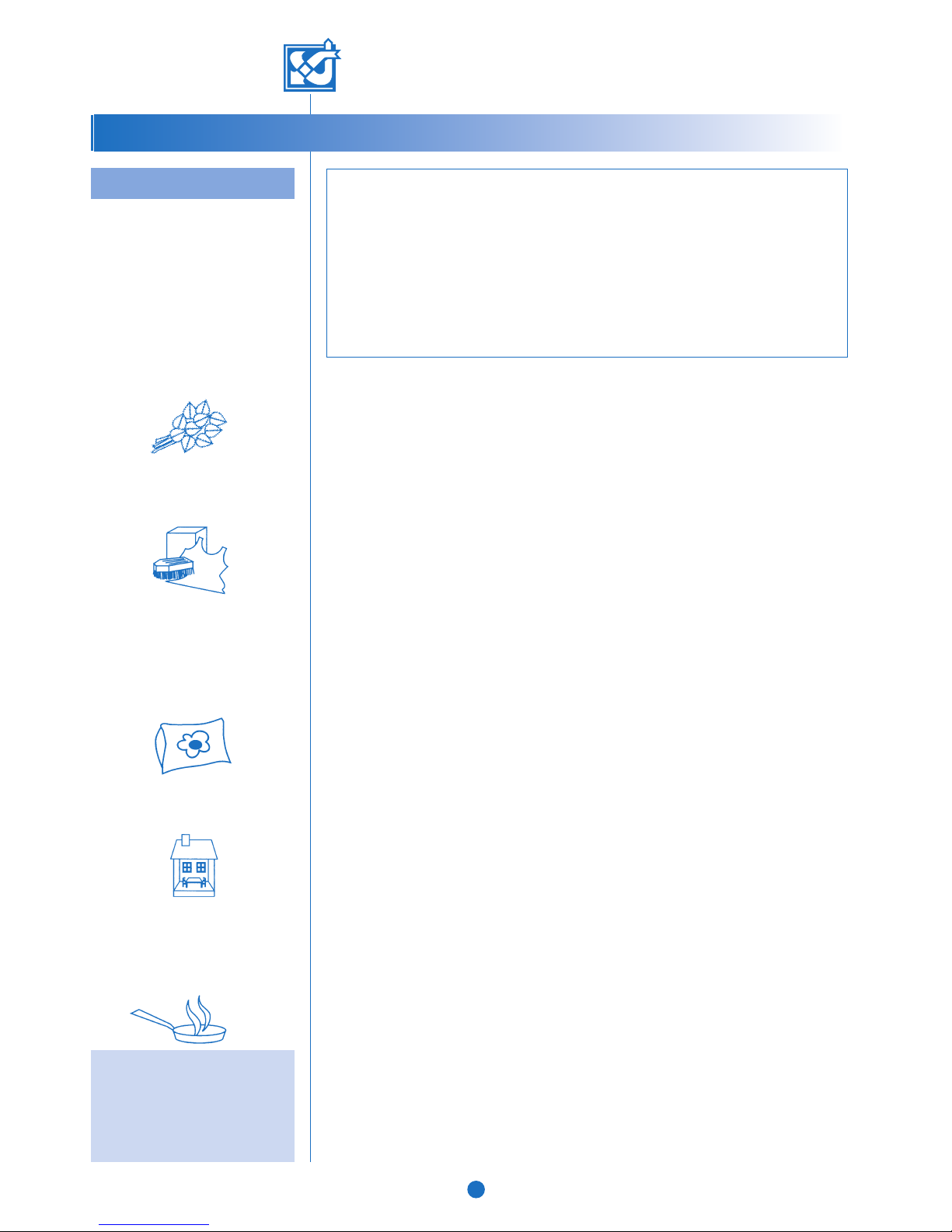
EVERYDAY QUICK GUIDE
NOTE!
Never switch ventilation off,
because ventilation keeps indoor air
quality uniform and removes gases
and dust emanating from the
structures.
• Taking a bath:
Boost ventilation in bathing and washing
facilities in order to ensure that the rooms
get dry as quickly as possible. It is advisable to have boosted ventilation on for 2 to 3
hours after taking a sauna bath, unless automatic adjustment based on humidity content is used.
• Washing and drying clothes:
Boost ventilation in washing and drying
rooms during the activity, unless automatic
adjustment based on humidity content is
used.
• Sleeping:
Ventilation in a bedroom has to be sufficient throughout the night. The level is correct when air does not smell fusty when
you enter the room in the morning. If the
carbon dioxide content of a room is monitored and ventilation is adjusted accordingly, air will always be fresh.
• Empty dwelling:
To save energy, ventilation can be adjusted
to the minimum level.
• Cooking:
If the ventilation unit is connected to a cooker hood, boost ventilation during cooking.
The most common way to abate cooking fumes is to have a separate
cooker hood.
© VALLOX • We reserve the right to make changes without prior notification.
Page 3
1. THREE QUESTIONS ABOUT VENTILATION
1.1. Why is air replaced in dwellings?
Good ventilation promotes healthy living for both residents and the building. Air in a dwelling needs to
be replaced in order to remove humidity brought about by living as well as impurities
emanating from structures and human bodies. Impurities of indoor air include carbon
dioxide, formaldehyde, radon and other gases as well as dust.
Mechanical ventilation is needed in order to be able to adjust air circulation as needed by
the residents. In a tightly sealed house, air does not circulate sufficiently by natural means.
Even in a poorly sealed house air is only replaced because of differences between indoor
and outdoor air temperatures, or because of winds. This means that ventilation is dependent
on weather conditions and cannot be regulated.
It is especially important that humidity and carbon dioxide content of the indoor air stay at a
healthy level. Recommended humidity content of good indoor air is approximately 45%.
Humidity content is lower in winter and higher in summer and autumn. Dust mites thrive in
indoor air if humidity exceeds 50%, and if humidity stays at over 60% for a long time in
winter, water condenses in the cold structures of the house and mould starts to form.
The recommended maximum carbon dioxide content in good indoor air is circa 1,000 ppm.
1.2. What are the characteristics of adequate ventilation?
• Indoor air stays fresh in all the rooms of the dwelling, also in bedrooms during night.
Without adequate ventilation, carbon dioxide content tends to rise high especially in
bedrooms.
• The bathroom and the sauna get dry quickly.
• During the heating season, the windows and other outer wall structures remain dry.
• Humidity in indoor air is not condensed in the ventilation ducts.
• Air is fresh in the toilet as well.
1.3. How much air is replaced?
For air to be clean to breathe, it has to be replaced with outdoor air every two hours.
In a new and a renovated house, air needs to be circulated continually, at least once an
hour, during the first year in order to remove harmful gases and structural humidity. In
buildings that are more than a year old and dry, ventilation can be regulated as needed.
Ventilation is boosted during for instance a sauna bath, clothes washing and cooking, and
reduced during very cold periods or when there is nobody at home. Carbon dioxide and
humidity sensors adjust ventilation in the rooms automatically as needed.
SEASONAL CALENDAR
NOTE!
For further details, see inner pages.
Autumn
• Wash or change the coarse filter and clean
or change the fine filter if needed. The
recommendation is approximately once a
year.
• Check that the heat recovery cell is clean.
• Check that the condensing water outlet is
not clogged.
• Switch the post-heating radiator on.
Spring:
• Wash or change the coarse filter and clean
or change the fine filter if needed.
• Clean the fan blades and the post-heating
unit if needed.
• Check that summer ventilation is in
operation.
• Switch the post-heating radiator off.
VALLOX DIGIT SE/SE VKL
THREE QUESTIONS ABOUT VENTILATION
3
4
1
2
3
43 1
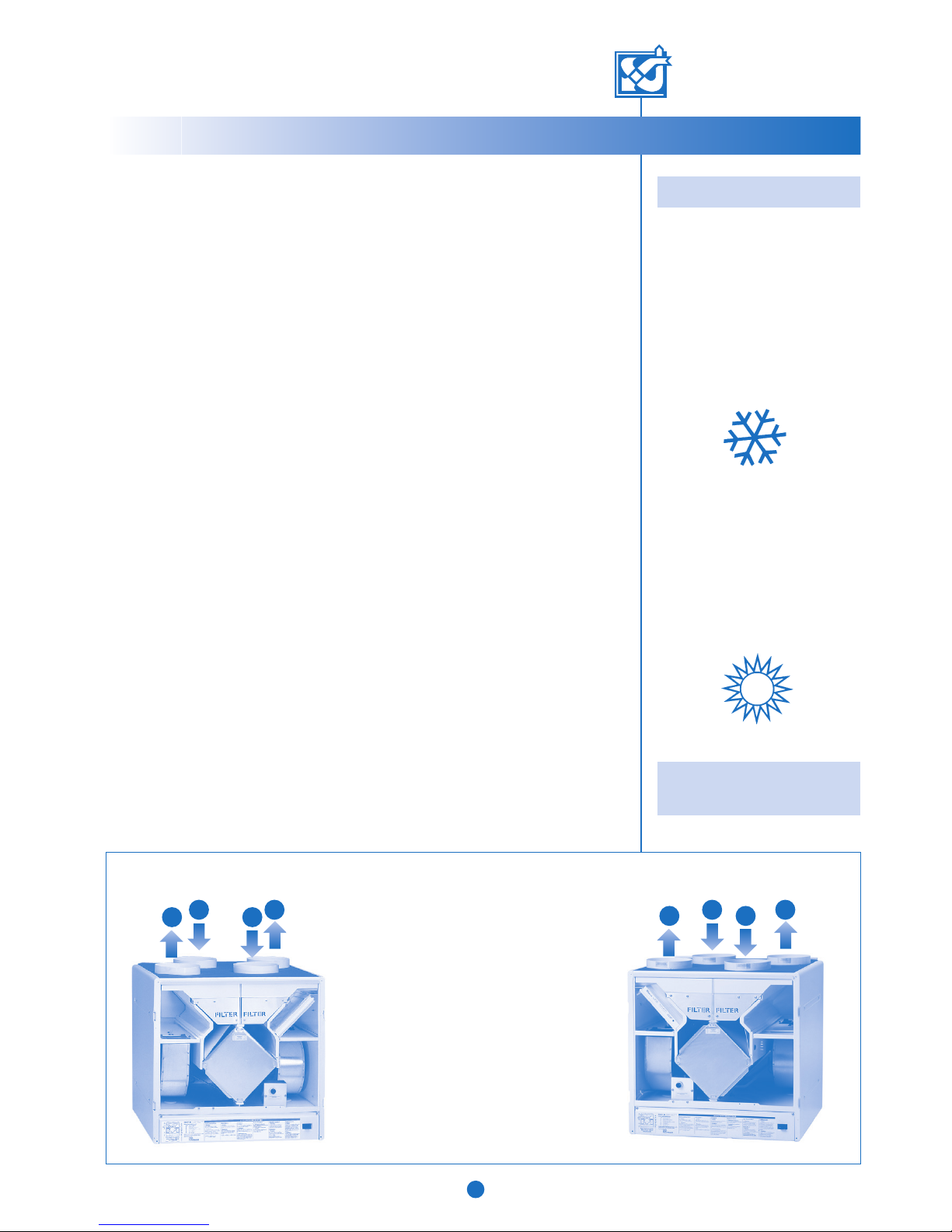
2
VALLOX DIGIT SE, order of duct outlets
1. Supply air to rooms
2. Extract air to the unit
3. Outdoor air to the unit
4. Exhaust air outside
R MODEL
1. Supply air to rooms
2. Extract air to the unit
3. Outdoor air to the unit
4. Exhaust air outside
L MODEL
© VALLOX • We reserve the right to make changes without prior notification.
Page 4
ELECTRONIC CONTROLLER
WITH LCD DISPLAY
VALLOX DIGIT SE/SE VKL
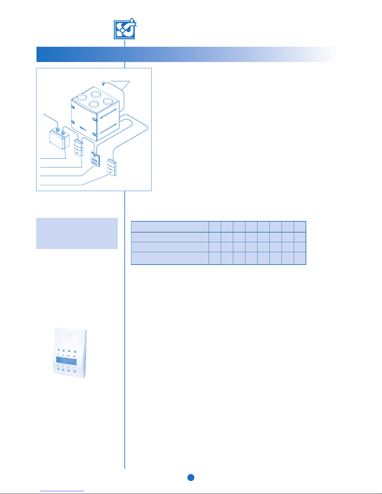
Plug
The table below shows the fan speed that is adequate for normal basic ventilation in dwellings
of different sizes, if there are no better measurement data available. The table also indicates
the total electricity consumption of the fans in each case.
1
50
40
2
92
60
3
130
90
4
165
125
5
215
160
6
245
200
7
275
235
8
330
305
Remember:Never turn DIGIT off,
or else you'llkeep catching a cough.
4
INSTRUCTIONS FOR USE
2.Instructions for use: VALLOX DIGIT SE
In order for indoor air to remain healthy, also for the structures of thebuilding,
ventilation has to be in continuous operation. Do not stop ventilation even for
longer holidays, because that will make room air musty, and during the heating
period room air humidity may condensate in theducts and the structures, thereby
causing humidity damage. The sensors automatically set ventilation to an optimal
level even if the house is empty.
2.1. Taking into use
1. Connect the plug into the power supply. VALLOX DIGIT SE is now readyfor
operation.
2. Start the unit and select an appropriate ventilation rate on the controlpanel.
The unit includes one or more control panels. For instructions on how to use
them, see Section 3.2.1. and 3.2.2.
In normal conditions, basic ventilation is adequate, which means that air isreplaced
once every two hours. Increased ventilation is neededduring sauna baths, cooking,
washing of clothes or family parties. If CO
2
and humidity sensors have been
installed in the system, VALLOX DIGIT SE will also take care of demand controlled
ventilation.
2.2. Ventilation control
The unit can be fully controlled with the control panel delivered with the unit or with an optional
LON converter.
The standard week clock control can be used to control the fan power of the unit and the
setpoint for supply air temperature.
Furthermore, demand controlled ventilation can be adjusted with optional carbon dioxide
and humidity sensors.
The fan power of the unit can also be controlled with a voltage or current signal.
2.3. Ventilation control with control panel
The following ventilation control functions can be performed at the control panel:
Ventilation rate regulation
• Starting and stopping
• Capacity regulation (8 positions).
• Setting the basic fan speed and the maximum fan speed. Ventilation rate cannot be set
lower than the basic fan speed. When CO
2
and/or %RH adjustments are activated,
capacity cannot be adjusted to exceed the maximum fan speed. When CO
2
and %RH
adjustments are not enabled, fan speed can be raised to speed 8.
Supply air temperature control functions
• Switching the electric or water-circulated post-heating unit on or off.
• Setting the desired supply air temperature (+10°C...+30°C).
• Choosing the control mode for desired supply air temperature (constant temperature
control, cascade control).
Preheating
• Setting the control temperature for the preheating unit (-6°C...+15°C exhaust air).
• Changing the setpoints.
Max 3 control panels may be in operation. When two or more control panels are used, the
most recent control function is the one that is valid.
DIGIT SED
SPEED
Living space (m
2
)
Living space (m3/h)
Total electricity consumption of the fans (W)
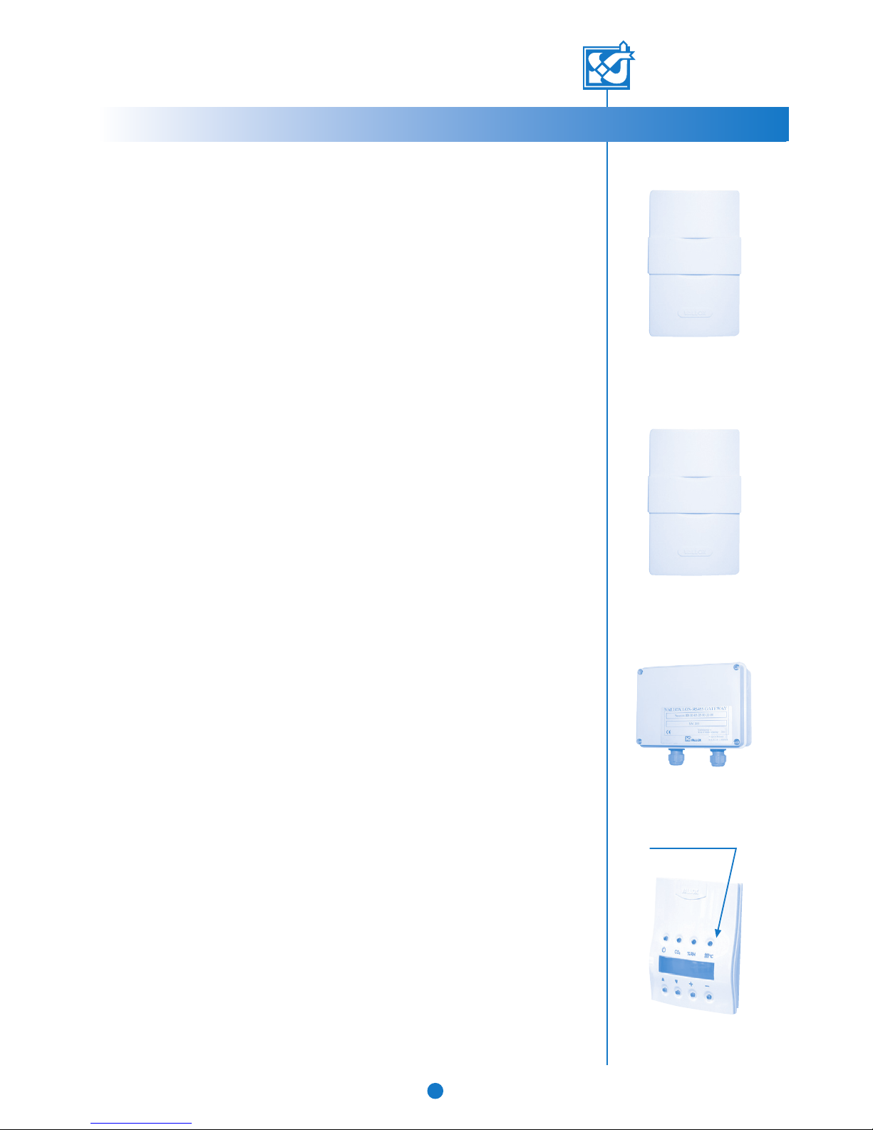
LON converter
Carbon dioxide sensor
Control panel
Humidity sensor
65
115
162 209 270 306 349 414
© VALLOX • We reserve the right to make changes without prior notification.
Page 5
VALLOX DIGIT SE/SE VKL
INSTRUCTIONS FOR USE
5
2.4. Ventilation control with carbon dioxide sensor (option)
• In carbon dioxide control, DIGIT SE adjusts fan speed so as to keep the carbon dioxide
content in the ventilation zone below the setpoint. If two or more sensors are used, fan
speed is adjusted in accordance with the highest measuring result.
• 1...5 optional carbon dioxide sensors may be connected to the VALLOX DIGIT SE unit.
• The adjustment is switched on / off and, if needed, the setpoint (500...2000 ppm) is
defined on the control panel. The factory setting is 900 ppm. The maximum carbon dioxide
content of indoor air should be 1000 ppm.
• While control is activated, you can use the control panel to raise fan speed to the maximum
speed and to lower it to the basic fan speed. In carbon dioxide control, maximum fan speed
limitation is enabled.
2.5. Ventilation control with humidity sensor (option)
Fan speed can be controlled in two ways:
1 Automatic humidity setting. This is suitable for controlling the washrooms in residential
buildings, for instance. The program records the current humidity level and defines it as the
setpoint used as the target value for making air dry after a shower, for instance. The setpoint
changes automatically according to season, and is always correct. This is the factory
setting.
2 You can also set a fixed humidity level of 1…99 %RH on the control panel. This setting can
be used in public saunas and public swimming pools. The program aims at maintaining
humidity at the chosen value. The setpoint can be changed as needed.
The mode of regulation is selected on the controller. The relative humidity of indoor air should
preferably be about 45%.
• While control is activated, you can use the control panel to raise fan speed to the maximum
speed and to lower it to the basic fan speed.
• In humidity control, the fan speed varies between the basic and maximum fan speeds set.
• When the unit is taken into use for the first time, with automatic setpoint search selected
(factory setting), it will take the program 3...10 hours to determine the value. During this
time, humidity control is not active (because the first value set at the factory is 100%).
• Automatic search is active, even if humidity control has not been selected.
2.6. Ventilation control with voltage or current signals
• The fan speeds of DIGIT SE can be controlled with voltage or current signals coming from
the remote monitoring system.
• The signal can be used to select speeds 0...8. However, the maximum fan speed may not
be exceeded if carbon dioxide or humidity control is active.
• The signal changes the basic fan speed.
• The signal does not lock the fan speed, i.e. it can be changed on the control panel within
the defined range. Carbon dioxide and humidity controls also operate within the defined
range.
2.7. Ventilation control with remote monitoring system (option)
• With the help of an optional LON converter, DIGIT SE can be connected to a remote
monitoring system.
• Before connecting DIGIT SE to the remote monitoring system, make sure that they are
compatible.
• The remote monitoring system may be used to control the same functions as on the control
panel.
• The remote monitoring system works in parallel with the control panel and the carbon
dioxide and humidity sensors.
2.8. Post-heating
For most of the year, the heat recovered from air to be extracted is enough to heat the cool air
coming from outside to a suitable temperature. If the heat of extract air is not enough, the air
coming from outside can be heated with the radiator included in the unit. The post-heating
radiator may be electric or water circulated. In both cases, heating can be activated on the
control panel (see section 3.1. of the instructions for use). When heating has been activated,
the unit automatically sets the temperature selected.
Carbon dioxide (CO2) sensor
Humidity (RH) sensor
2.8.
LON converter
© VALLOX • We reserve the right to make changes without prior notification.
Page 6
VALLOX DIGIT SE/SE VKL
6
INSTRUCTIONS FOR USE
Remember:
Switch post-heating off when it gets
too warm in the dwelling. Switch postheating on again when it gets cooler in
autumn.
2.9. Supply air constant temperature control
• In DIGIT SE, post-heating control is proportional: when the chosen temperature exceeds
supply air temperature by more than 2.5°C, the radiator is on 100% of the time; when the
temperature differential gets smaller, the on time of the radiator is reduced automatically in
two-minute sequences. The temperature range is 10…30°C.
• The heating radiator is on when the
-sign is displayed.
• Temperature control is only active when post-heating has been switched on.
2.10. Supply air cascade control
• Supply air temperature control can be replaced with cascade control.
• Cascade control changes the mode of regulating the post-heating radiator: the temperature of
air blown to the ventilation zone is controlled on the basis of extract air.
• The program aims at keeping supply air temperature at the value that depends on the
difference between extract air and the setpoint as follows: if extract air is hotter than the
setpoint, the temperature of supply air is lower than the setpoint by the same amount. If extract
air is cooler than the setpoint, supply air is hotter by the same amount. For instance, if indoor
air temperature is 25°C and the setpoint is 24°C, the aim is to blow 23°C air to the ventilation
zone. If the temperature in the ventilation zone is 24°C and the setpoint is 25°C, the aim is to
blow 26°C air to the ventilation zone.
• The aim is to permanently keep the temperature of air blown to the ventilation zone within the
range 10...30 °C.
• Cascade control can be chosen on the control panel, and it is active when post-heating has
been switched on.
• The heating radiator is on when the
-sign is displayed.
2.11. Heat recovery bypass
• The aim of the heat recovery bypass function is to ensure that supply air coming to the
ventilation zone is as cool as possible. To do this, the heat recovery bypass function compares
the measurement data of the outdoor and extract air sensors.
• The heat recovery cell is bypassed, when the post-heating function is off, when outdoor air
temperature exceeds two degrees the setpoint and when extract air is hotter than outdoor air.
• The setpoint can be changed between 0…+25°C. (Factory setting 10°C).
2.12. Heat recovery defrost function and preheating
• Defrost prevents the heat recovery cell from freezing, thus ensuring proper ventilation even in
cold periods.
• In a standard ventilation unit, defrosting is implemented by intermittently stopping the supply
air fan. The stopping function is controlled on the basis of the measurement data given by the
temperature sensor that measures the temperature of exhaust air after the heat recovery cell.
• The supply air fan stops when exhaust air temperature falls to the setpoint (factory setting
+4°C) and starts when exhaust air temperature has risen to the value set (hysteresis setting,
factory setting +3°C).
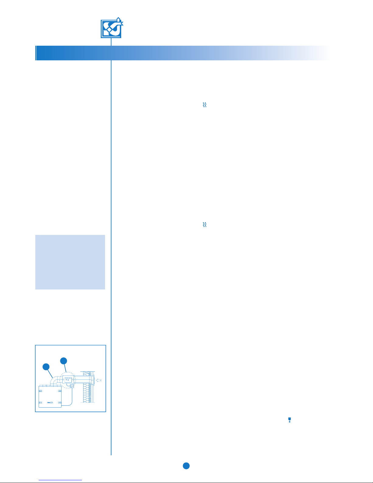
Preheating
• The system can also be equipped with an optional preheating facility. The preheating radiator
(A) has been installed in the outdoor air duct (B). It is switched on before the supply air fan
stops. The operation is controlled by the same sensor that has been installed in exhaust air.
The heater is switched on at a temperature higher than the stopping temperature (factory
setting +6°C). If preheating cannot keep exhaust air temperature warmer than the stopping
temperature, the outdoor air fan stops. When the risk of freezing has passed, preheating is
switched off and the supply air fan starts automatically.
• Post-heating is on throughout the freezing risk period.
2.13. Maintenance reminder
• The maintenance reminder switches on the maintenance reminder symbol ( ) in the main
display of the control panel at defined intervals, the factory setting being 4 months.
• The maintenance reminder symbol is acknowledged at the control panel (see the instructions
for using the control panel, Section 3.3.10.).
• The interval can be set between 1...15 months at the control panel.
A
B
© VALLOX • We reserve the right to make changes without prior notification.
Preheating
Page 7
VALLOX DIGIT SE/SE VKL
B
C
A
Heat recovery cell
Pressure difference switch
7
INSTRUCTIONS FOR USE
2.14. Filter guard function
• If DIGIT SE is equipped with a pressure difference switch for the supply and/or extract air
ductwork, the switch monitors the pressure difference in the whole ductwork. When
pressure has risen (e.g. because of a clogged filter), the filter guard symbol (
) in the main
display of the control panel is lit up.
• The filter guard closes the points of the fault signal relay, and the filter guard symbol (
) is
seen in the main display.
• The maintenance reminder is on even during this function.
• The operation threshold for the pressure difference switch is adjusted at the pressure
difference switch regulator (0…500 Pa). Factory setting is ca. 260 Pa; the setting can be
changed if needed. With clean filters, the symbol should light up at speeds 7 and 8.
2.15. Anti-freeze function in water-circulating post-heating unit
• The anti-freeze function aims at preventing a water-circulating post-heating unit from
freezing. The automatic function stops the supply and extract air fans as soon as outdoor
air temperature falls below 0 °C and supply air temperature falls below +7 °C. At the
same time, the self-actuated dampers of the fans close and the control valve becomes
wide open. The control panel displays the fault message FREEZING ALERT, irrespective of
display.
• The fans start automatically and the dampers open as soon as supply air temperature
exceeds 10 °C.
2.16. Fireplace switch / boosting function
Fireplace switch function
• The fireplace switch stops the extract air fan for 15 minutes and causes overpressure in
the ventilation zone. This facilitates lighting up the fireplace, for instance.
• The function is activated by pressing a self-resetting push-button switch. On each pressing
of the switch, the stopping function goes on for 15 minutes.
• During the function, the fireplace/booster switch symbol (
) is visible in the main display
of the control panel.
Note! When the extract air fan starts, the draft in the fireplace may get weaker!
In cold winter, the anti-freezing and defrosting functions may start when cool air flows to the
extract air ducts. If the post-heating radiator does not contain any non-freezing liquid, there
is a risk of freezing. The situation will get back to normal some time after the function has
stopped.
Booster switch function
• The booster switch raises fan speed to the preset maximum fan speed for 45 minutes.
• The function is activated by pressing a self-resetting push-button switch. On each pressing
of the switch, the stopping function goes on for 45 minutes.
• During the function, the fireplace/booster switch symbol (
) is visible in the main display
of the control panel.
• The function is selected on the control panel.
© VALLOX • We reserve the right to make changes without prior notification.
2.17. Fault signalling relay (remote monitoring)
• The fault signalling relay has potential free points (24VDC, 1A).
• The points provide information on failure modes of the ventilation unit.
• During water radiator defrosting, the points of the relay close and
open at 10- second intervals.
• High carbon dioxide content alarm switches the relay every second.
• In other failure situations, the points are closed.
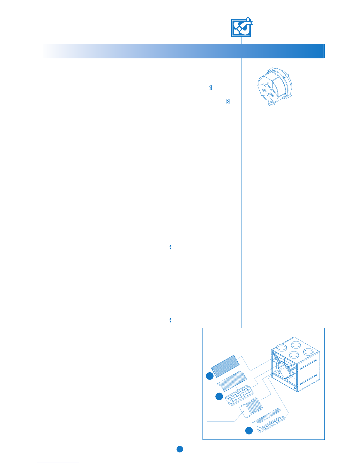
2.18. Air filtration
DIGIT SE VALLOX DIGIT SE features coarse filtering of both extract and
supply air before the fans. The unit has a F7 class (B) fine filter and a G3
class (A) coarse filter on the supply side, and a G3 class (C) coarse filter
on the extract side. The filters need to be in place in the unit whenever
ventilation is in operation.
Page 8
Fan speed (3).
Supply air temperature (21 °C).
Post-heating is on.
Time.
Filter guard alert.
Maintenance reminder alert.
Fireplace / booster switch on. The fireplace /
booster switch is activated in this display by
simultaneously pressing down the + and – buttons
for 2 seconds.
Week clock control on.
21 C
10:20
1 2 3 4
5 6 7 8
VALLOX DIGIT SE/SE VKL
INSTRUCTIONS FOR USING THE CONTROL PANEL
8
© VALLOX • We reserve the right to make changes without prior notification.
3.2. Operating menu
In order to move the control panel to the settings menu, press the + and – buttons simultaneously.
In the settings menu, you can change setpoints for the ventilation unit.
The content display shows humidity and carbon dioxide content. The corresponding
sensors are required (options).
The temperature display shows the temperatures of outdoor air, indoor air, supply air
and exhaust air. The accuracy of the temperature sensors is ± 2 °C.
Supply air temperature setting is changed with the + and – buttons.
3.2.1. Main display and change of fan speed
3.2.2. Moving to the settings menu
3.2.4. Content display
3.2.5. Temperature display
3.2.6. Setting supply air temperature
Fan speed can be changed in this display with the + and – buttons
(see section 3.1., items 7 and 8 in the figure).
The displays of the operating menu (sections 3.2.1.–3.2.6.) can be scrolled with the scrolling buttons
(see section 3.1., items 5 and 6 in the figure).
To settings menu
See manual
RH1 35% RH2 40%
CO2 0821 PPM
Out 20 In 20
Sup. 20 Exh. 20
Temp. setting
20C
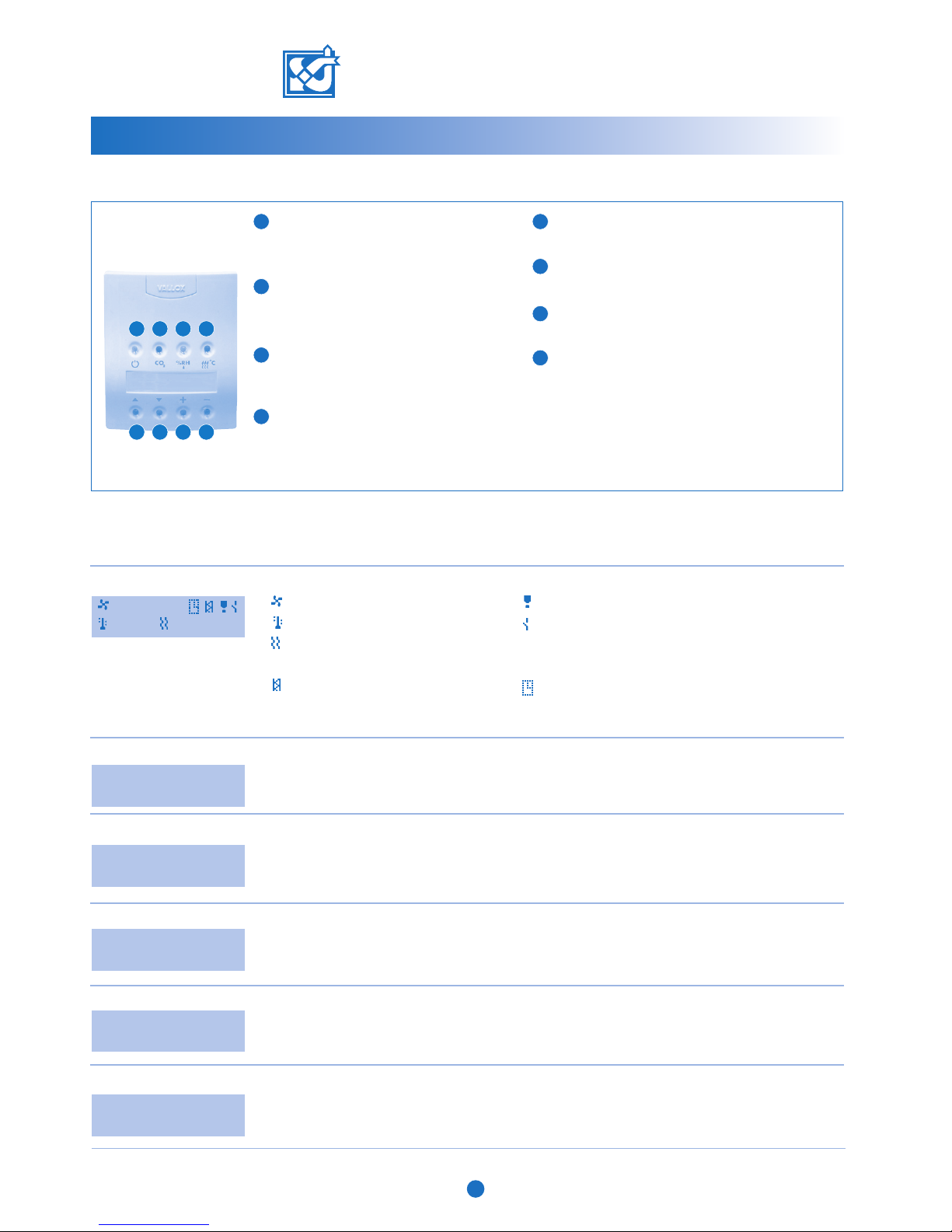
5
Scrolling up
With this button, you can scroll the displays upward.
6
Scrolling down
With this button, you can scroll the displays downward.
7
Increase button
With this button, you can increase values.
8
Decrease button
With this button, you can decrease values.
2
Carbon dioxide adjustment
With this button, you set carbon dioxide
adjustment on and off. When the indicator is
lit, the adjustment is on.
3
Humidity adjustment
With this button, you set humidity adjustment
on and off. When the indicator is lit, the
adjustment is on.
4
Post-heating
With this button, you set post-heating on and
off. When the indicator is lit, post-heating is on.
The summer function is active when the indicator
is not lit.
3.1. Keyboard
Power failure
After a power failure, the unit starts at minimum
fan speed. The adjustments and setpoints chosen
will remain in the memory of the unit in spite of
the power failure.
3. Control panel
1
Start button
With this button, you switch the unit on and off.
When the indicator is lit, the unit is on.
3
21 C
3
10:20
Week clock control can be activated by pressing the + button and deactivated by pressing the –
button. Week clock control is on when the symbol of week clock control is shown in the main
display. In week clock control, the basic fan speed and supply air temperature of the unit are
adjusted in accordance with the programme in section 3.3.4.
3.2.3. Week clock control
Week program
on
Page 9

VALLOX DIGIT SE/SE VKL
9
INSTRUCTIONS FOR USING THE CONTROL PANEL
© VALLOX • We reserve the right to make changes without prior notification.
3.3. Settings menu
You can reach the settings menu from the operating menu as indicated in section 3.2.2. The displays of the settings menu
(sections 3.3.1.–3.3.26.) can be scrolled with the scrolling buttons (see section 3.1., items 5 and 6 in the figure).
3.3.1. Setting the basic fan speed
The desired basic fan speed (minimum fan speed) is selected with the + and – buttons. Active when
week clock control is not on. Week clock control changes this speed.
MIN speed
1
3.3.2. Moving to the operating menu
You can return to the operating menu by pressing the + and – buttons simultaneously.
To main menu
Press + and -
The maximum fan speed setting can be selected to be active either in connection with (carbon dioxide
and humidity) adjustments or permanently. The selection is done with the + and – buttons.
3.3.6. Mode of operation of the maximum speed setting
MAX Speed limit
with adjustments
Select the desired language (German, English, Swedish, French or Finnish) with the + and – buttons.
3.3.7. Choosing the language version
Kieli / Language
English
The general factory settings can be restored by pressing the + and – buttons simultaneously.
Remember to ensure that the setpoints are in accordance with the factory settings for this unit.
Especially, check the unit model (electricity / water) and change if needed as stated in section
3.3.20.
3.3.8. Restoring factory settings
Factory settings
see manual
The adjustment interval for humidity and carbon dioxide adjustments is selected with the + and –
buttons. The adjustment interval refers to minutes.
3.3.9. Adjustment interval
Adjust interval
10
The maintenance reminder is reset by pressing the + and – buttons simultaneously. This
turns out the maintenance reminder symbol ( ) in the main display.
3.3.10. Resetting the service reminder
Mainten. reset
Press + and -
The contrast setting for the control panel display is changed with the + and – buttons.
3.3.11. Contrast of the control panel display
Display contrast
05
The week programme can be totally erased by simultaneously pressing the + and – buttons.
3.3.3. Erasing the week programme
Erase week prog.
Press + and -
You can access the programming mode for the week clock programme by simultaneously pressing
the + and – buttons. See section 3.4.1.
3.3.4. Week programme programming
Adjust week prog.
Press + and -
You can adjust time by simultaneously pressing the + and – buttons. For more details, see section
3.4.2.
3.3.5. Adjusting time
Adjust time
Press + and -
The address of the control panel is changed with the + and – buttons. Two control panels cannot
have the same address. If control panels have the same address, they will go to the bus fault state
and will not operate.
3.3.12. Address of the control panel
Panel address
1
The desired adjustment value for the DC fan is selected with the + and – buttons. The rotation speed
of the extract air fan can be lowered by decreasing the percentage value. If the unit has alternating
current fans, this adjustment has no impact on the operation of the unit.
3.3.13. Adjusting the direct current fan on the extract air side (does notrefer VALLOX DIGIT SE)
DC fan exhaust
100%
Page 10

The preheating temperature for the anti-frost function in the heat recovery cell is
chosen with the + and – buttons.
3.3.24. Pre-heating temperature for the anti-frost function in the heat recovery cell
Preheater
07C
VALLOX DIGIT SE/SE VKL
INSTRUCTIONS FOR USING THE CONTROL PANEL
10
© VALLOX • We reserve the right to make changes without prior notification.
The hysteresis of the anti-frost function in the heat recovery cell is selected with the + and – buttons.
3.3.22. Hysteresis of the anti-frost function in the heat recovery cell
Hysteresis
03C
The interval for the maintenance reminder is selected with the + and – buttons. The
maintenance reminder interval refers to months.
3.3.21. Choosing maintenance reminder interval
Maintenance rem.
04
A water or electric radiator is selected with the + and – buttons, depending on the type of postheating radiator the unit is equipped with.
Note! Choosing the wrong type of post-heating causes a faulty post-heating function.
3.3.20. Choosing post-heating for the unit
Radiator type
electric rad.
The basic humidity level can be chosen as either automatic or manual. The selection is
done with the + and – buttons.
3.3.19. Choosing the basic humidity level
Rh-level setting
automatic
The desired setpoint is chosen with the + and – buttons when manual adjustment has been selected
as the Rh level setting (humidity setting, section 3.3.19).
3.3.16. Setpoint of the basic humidity level
Basic %RH level
40%
The desired cell bypass temperature is selected with the + and – buttons. If outdoor temperature
is lower than cell bypass temperature, the summer / winter damper is in the winter position.
3.3.15. Changing the operating temperature of heat recovery cell bypass
Cell bypass
10C
The desired adjustment value for the DC fan is selected with the + and – buttons. The rotation speed
of the supply air fan can be lowered by decreasing the percentage value. If the unit has alternating
current fans, this adjustment has no impact on the functioning of the unit.
3.3.14. Adjusting the direct current fan of the supply air side (does not refer VALLOX DIGIT SE)
DC fan - supply
100%
The mode of operation of the switch (either fireplace or booster switch) is selected
with the + and – buttons.
3.3.17. Mode of operation of the fireplace / booster switch
Switch type
Fireplace switch
Cascade control is activated or deactivated with the + and – buttons.
3.3.18. Choosing cascade control for supply air temperature
Cascade adjust
Off
The setpoint for CO2 adjustment is chosen with the + and – buttons.
3.3.25. Changing the setpoint for carbon dioxide adjustment
CO2-setting
0900 PPM
The desired maximum fan speed is selected with the + and – buttons. Maximum fan
speed is on either with adjustments or permanently. See section 3.3.6. Mode of
operation of the maximum speed setting.
3.3.26. Choosing maximum fan speed
MAX speed
8
The stopping temperature of the supply air fan for the anti-frost function in the heat
recovery cell is chosen with the + and – buttons.
3.3.23. Stopping temperature of the supply air fan for the anti-frost function in the heat recovery cell
Supply fan stop
05C
Page 11

VALLOX DIGIT SE/SE VKL
11
INSTRUCTIONS FOR USING THE CONTROL PANEL
© VALLOX • We reserve the right to make changes without prior notification.
3.4. Week clock control
The week programme can be used to set the desired fan speed (basic fan speed) and supply air
temperature for each hour of the day on seven days a week. The week programme overrides
manual adjustments.
Carbon dioxide and humidity adjustment can increase fan speed but never decrease it below the
basic fan speed set in the week programme.
3.4.1. Week programme programming
D Hr Sp Tmp
1 12 5 20 Exit
Cursor
D Day 1…7
1 = Monday, 2 = Tuesday, etc.
Hr Hours, 0…23
Sp Fan speed, 1…8
Tmp Supply air temperature, 10...30 ºC
Exit Save the setting and exit
N No change to previous
Example: Monday
Fan speed is increased to speed 2 and supply air temperature to 17 ºC between 07:00 (7 a.m.)
and 17:00 (5 p.m.) hours. After that, fan speed is raised to speed 4 and supply air temperature to
20 ºC. For the evening, fan speed is boosted to speed 6 between 19:00 and 21:00 hours (for the
period when a sauna bath is taken), after which fan speed is lowered back to 4.
Move the cursor with the arrow keys and change values with the + and – buttons. Note that Exit
and saving are done when the programming is finished by moving the cursor below the word Exit
and pressing + or –.
Changes in fan speed (Sp) and supply air temperature (Tmp) are only made for the hours desired;
in other cases, use N (no change to previous).
Monday (D = 1), 07:00 hours (H = 7), fan speed 2 (Sp = 2), supply air temperature 17 ºC (Tmp =
17). Move the cursor to the following hour.
Monday (D = 1), 16:00 hours (H = 16), fan speed 4 (Sp = 4), supply air temperature 20 ºC (Tmp
= 20). Move the cursor to the following hour.
Monday (D = 1), 19:00 hours (H = 19), fan speed 6 (Sp = 6), supply air temperature unchanged
(Tmp = N). Move the cursor to the following hour.
Monday (D = 1), 21:00 hours (H = 21), fan speed 4 (Sp = 4), supply air temperature unchanged
(Tmp = N). Move the cursor to the following day.
Similar changes have to be made separately for each day. Finally, exit the programming mode by
selecting Exit. If you wish, you can erase the week programme as indicated in section 3.3.3. You
can then start programming from the start. You can see the settings programmed by choosing a day
and by scrolling the hours with the + or – button.
D Hr Sp Tmp
1 7 2 17 Exit
D Hr Sp Tmp
1 16 4 20 Exit
D Hr Sp Tmp
1 19 6 N Exit
D Hr Sp Tmp
1 21 4 N Exit
Move the cursor with the arrow keys and change values with the + and – buttons. Exit
and saving are done when the programming is finished.
Monday (D = 1), hours 15 (H = 15), minutes (M = 30).
Time is maintained even though there is a power failure.
3.4.2. Adjusting time
day hour min
1 15 30 Exit
day Day 1…7
1 = Monday, 2 = Tuesday, etc.
hour Hours, 0…23.
min Minutes 0…60
Exit Save the setting and exit
Cursor
Page 12

VALLOX DIGIT SE/SE VKL
12
INSTRUCTIONS FOR USING THE CONTROL PANEL
© VALLOX • We reserve the right to make changes without prior notification.
Basic fan speed = 1
Maximum fan speed = 8
Carbon dioxide adjustment (CO
2
) = 900 ppm CO
2
Basic humidity level = value chosen either automatically or manually
Adjustment interval = 10 min.
Freezing protection (cell) = 4°C
Freezing protection hysteresis = 3°C
Preheating setpoint = 6°C with preheating, otherwise 1°C
Maintenance reminder = 4 months
Cell bypass = 12°C
Cascade control = not active
Humidity level (RH level) adjustment = automatic
Switch type = fireplace switch
3.5. Factory settings
Page 13

VALLOX DIGIT SE/SE VKL
MAINTENANCE INSTRUCTIONS
13
B
A
A
C
T
Preheating
B
A
D
C
F
E
REMEMBER:
Clean the filters at least twice a year. Define the
maintenance reminder interval to suit your
needs; see the instruction in section 3.3.21.
(The interval is dependent on the purity of outdoor and indoor air).
The fine filter (B) cannot be cleaned with water. Clean it in connection with the cleaning
of the G3 filters, vacuuming it with a brush roll. When cleaning, take care not to break
the filtration material. To ensure good supply air quality, replace the filter when needed, preferably at
one-year intervals, depending on local air quality. It is recommended to replace the filters in the
autumn. In this way, the filter will stay fresh during the winter and will efficiently filter dust
in the following spring.
It is advisable to check the cleanliness of the heat recovery cell (C) about every two years,
in connection with the cleaning of the filters. Holding the ears at the end of the cell, pull
the cell out of the unit. If the cell is dirty, wash it by sinking it to water containing washingup
liquid. Rinse the cell clean by showering it with water. When water has flown from between
the sheets, push the cell back into the unit, making sure the sealings against the slide surfaces
are in place and that the "this side up" label at the end of the cell points to the corner
against the upper support.
4. MAINTENANCE INSTRUCTIONS
4.1. Filters
When the maintenance reminder or the filter guard light the indicator
lamp, check the cleanliness of the filters. Outdoor air is filtered in the unit
with two kinds of filters. The G3 coarse filter (A) filters insects and coarse
pollen and dust. The F7 fine filter (B) filters fine dust that is not discernible
to the eye. Extract air is filtered with a similar G3 filter as outdoor air.
Clean the coarse filters (A) when needed i.e by washing them 2 to 4 times
a year and whenever the filter guard indicates a need for maintenance.
When you open thedoor of VALLOX DIGIT SE, the safety switch (T) turns
the unit off. Clean the filters with 25…30°C water and washing-up liquid,
pressing them lightly. Do not handle the filters with force. When properly
cleaned, the filters stand cleaning 3 to 4 times. This means they have to be
replaced every two years or when needed.
The filters and the heat recovery cell. Units are
either right- or left-handed. In the right-handed
model (R) outdoor air comes to the unit from
the right side of the center line as in these
instructions. In the L model, outdoor air comes
from the left side of the unit. The filters, summer
/ winter damper and heating radiator are also
on opposite sides as compared to the R model.
4.1.1 Preheating filter
If the system has been equipped with optional preheating for preventing
the heat recovery cell from freezing, it needs to be serviced at least twice
a year. The heater (A) has been installed in the outdoor air duct (B).
Remove the plug (C) and inner part (D) of the heater. After this, you can
pull out the filter (E) and its frame (F). Remove the filter from the frame.
You can vacuum the filter or carefully wash it in water under 40°C and
a detergent. If the filter is damaged, replace it with a new one. Only use
original filters in the heater. USING THE HEATER WITHOUT FILTER IS PROHIBITED.
Clean the heater of litter and insects at the same time.
© VALLOX • We reserve the right to make changes without prior notification.
Page 14

4.2. Fans and post-heating radiator
The supply and extract air fans (D and E) have been fastened with rubber
collars (F). When removing the fans for maintenance, remove the one-way
dampers (L) from the VKL model, open the ear (K) attached to the fan, bent
over the rubber collar. Then lift the rubber collar away and turn the fan away
from above the lower support (M) made of rubber. Then take the electrical
connector (G) off from behind the fan.
Clean the fan blades with compressed air.
If you use water when cleaning the unit or its parts, do not let water enter the electric parts.
For cleaning the post-heating radiator (J), remove the filters and the heat
recovery cell. Clean the post-heating radiator while it is in place in the unit
either by vacuuming it or blowing it with compressed air. The radiator can be
either electric or water circulated. If needed, you can remove the electric
radiator for maintenance by removing the electrical connector (H) as well as
the two tightening-up screws (I) and the adhesive or screw fixing the support
against the bottom reservoir.
4.2.1. Detaching and attaching of one-way damper.
Detaching and attaching of self-actuated one-way damper (vacuum damper):
A Put the hook on the rim of the damper (Y) under the side edge of the
fastening collar (K) of the fan (F). Then push the damper downwards so
that the guide edges of the valve go inside the rubber collar.
B Push the other side of the collar with a finger.
C Put the hook on the other side edge of the damper below the edge of the
collar.
To detach the damper take the same steps in the opposite order.
Self-actuated one-way dampers are only used in VKL model units. Observe
the position of the damper so that it can also operate on the F7 filter side.
4.3. Filter guard
DIGIT SE can be equipped with an optional filter guard. The filter guard symbol ( ) normally
lights up in the main display at speeds 7 and 8, when the filters are clean, and this does
not cause any service activities. If the symbol does not light up at speed 8, the pressure in
the ventilation ductwork of the building differs from the factory setting. In that case, adjust
the filter guard setpoint lower in the inside of the unit (see Section 2.14). If the filter guard
symbol lights up at fan speed 4 or 5, the filters need cleaning. If they are clean, the lighting
up may be caused by too dense a mosquito net installed in the external grille or by the
closing of the supply air valves in the rooms. If, after checking these things, the symbol
continues to light up at small speeds, adjust the setpoint greater.
4.4. Condensing water
During the heating season, the humidity in extract air condenses as condensing water. Water
formation may be abundant in new buildings or if ventilation is scarce in terms of moisture
production by the inhabitants. The condensing water must exit the unit without hindrance.
In connection with maintenance operations, for example in the autumn before the start of
the heating season, make sure that the condensing water joint (L) in the bottom reservoir is
not clogged. You can check this by pouring a little water in the reservoir. Clean if needed.
Do not let any water enter the electrical devices.
VALLOX DIGIT SE/SE VKL
14
MAINTENANCE INSTRUCTIONS
© VALLOX • We reserve the right to make changes without prior notification.
F
K
Y
F
K
Y
F
K
Y
F
K
Y
A B C
F
P
L
E
G
D
G
H
I
J
M
M
L
F
K
K
Q
Page 15
15
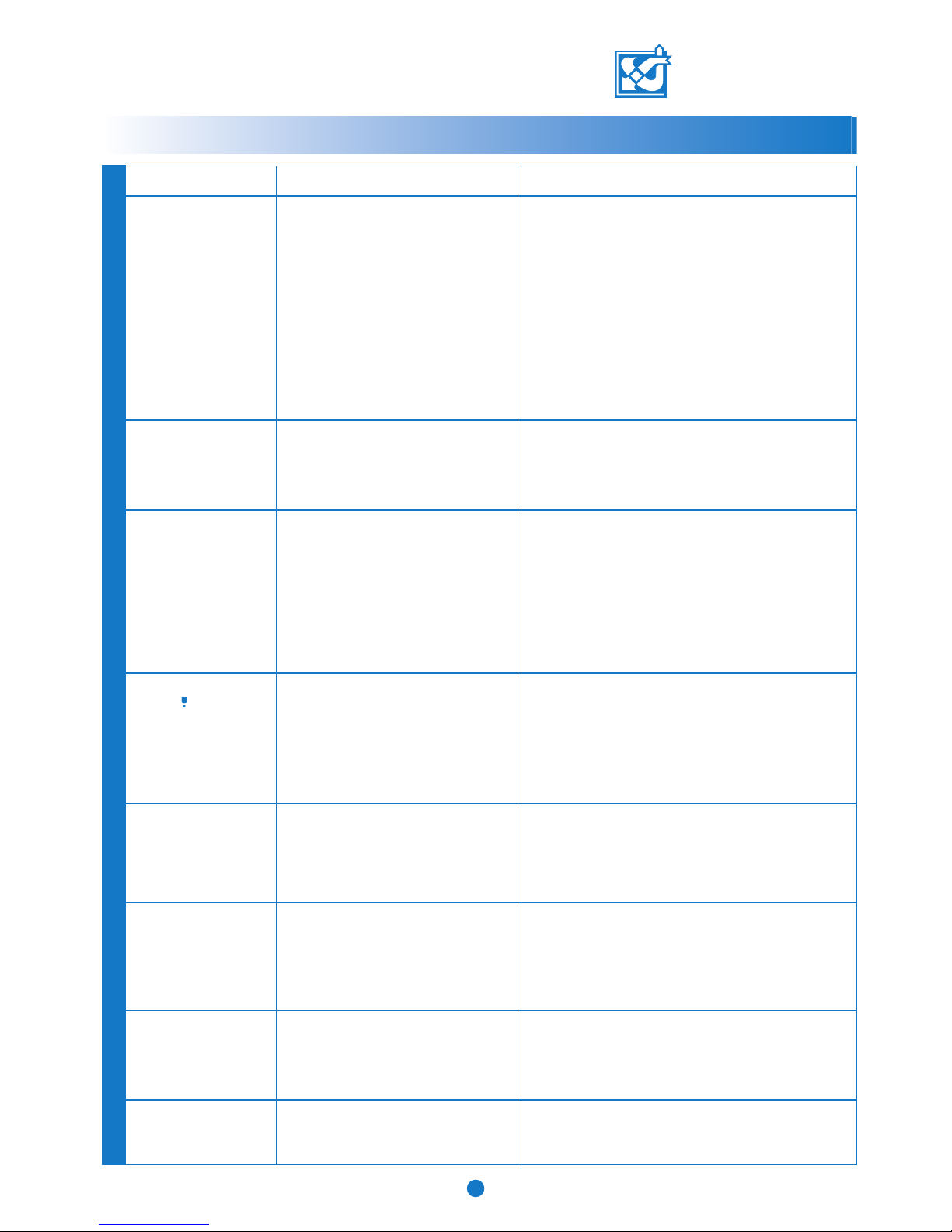
TROUBLESHOOTING
VALLOX DIGIT SE/SE VKL
© VALLOX • We reserve the right to make changes without prior notification.
Outdoor air coming to
the dwelling is cold.
SYMPTOM REASON DO THIS
• Air cools down in the attic ducts.
• The heat recovery cell is frozen, which is
why extract air cannot heat outdoor air.
• The post-heating radiator does not work.
• The extract air filter or the cell is clogged.
• The initial adjustment of ventilation has not
been done.
1
• Check the insulation of the attic ducts.
• If the heat recovery cell is frozen, check the setpoint for
freezing protection. The setpoint for freezing protection can
be raised by 1 or 2 °C, or the sensor can be bent closer to
the cell, in which case the supply air fan stops earlier (see
the instructions for using the control panel in Section
3.3.23.). Thaw the cell before closing the door.
• If the post-heating radiator does not operate, check to see if
overheating protection prevents it from operating. Press the
overheating protection reset button (see page 14, Q), and
measure the temperature of supply air inside the unit when
the door is closed. If the radiator does still not work, contact
a maintenance company.
• Check that the filters and the heat recovery cell are clean.
Supply air fan keeps stopping
• HR cell antifreeze is in operation.
NOTE! If you decrease the setpoint too much, the
cell may freeze. Compare with list item 1.
2
• The fan stops more rarely and the efficiency of the heat
recovery cell gets better when the setpoint is decreased by
1 or 2 °C. (See the instructions for using the control panel,
Section 3.3.23.)
Supply air fan stops and
starts too frequently.
• The difference between the stopping and
starting temperatures is too small.
• The preheating radiator does not work.
3
• Raise the difference between the stopping and starting temperatures by 1 or 2 °C. It extends the period between stopping and starting. (See the instructions for using the control
panel, Section 3.3.22.)
• If the preheating radiator does not operate, check if overheating protection prevents it from operating: press the
overheating protection reset button, and measure the temperature of outdoor air inside the unit before the heat recovery
cell when the door is closed. If the radiator does still not
work, contact a maintenance company.
The maintenance reminder
symbol ( ) is displayed and
the unit operates otherwise
normally.
• The maintenance reminder lights up the
service reminder symbol in the main
display of the control panel at an interval
of approximately 4 months (factory
setting).
• You may change the interval (see the
instructions for using the control panel,
Section 3.3.21.).
4
• Check the cleanliness of the filters and the unit. If needed,
clean or replace the filters. Also check the external grille.
• Reset the maintenance reminder symbol to make it
disappear. (See the instructions for using the control panel,
Section 3.3.10.)
"Exh air sensor faulty"
message is displayed and
the unit is stopped.
• There is a fault in the freezing protection
sensor.
5
• Contact a maintenance company. Sensor mounting needs to
be checked and the sensor has to be replaced if necessary.
"Sup. air sensor faulty"
message is displayed and the
unit is stopped.
• There is a fault in the supply air sensor.6• Contact a maintenance company. Sensor mounting needs to
be checked and the sensor has to be replaced if necessary.
"Inp. air sensor faulty"
message is displayed and the
unit is stopped.
• There is a fault in the extract air sensor.7• Contact a maintenance company. Sensor mounting needs to
be checked and the sensor has to be replaced if necessary.
"Out air sensor faulty"
message is displayed and the
unit is stopped.
• There is a fault in the outdoor air sensor.8• Contact a maintenance company. Sensor mounting needs to
be checked and the sensor has to be replaced if necessary.
Page 16
"Bus fault" message is
displayed and the unit
operates at speed 1
(check the fan speed).
• Wiring fault in the carbon dioxide sensor,
in the control panel or in the humidity
sensor.
9
• Contact a maintenance company. The connections have
to be checked and corrected if necessary.
"Freezing alert" message
is displayed and the unit is
stopped.
• Antifreeze of the water-circulating radiator
is active.
NOTE! If there is no non-freezing solution in the
water of the radiator, the radiator is at risk of
freezing.
10
• Immediately troubleshoot the situation. Consult a
maintenance company to find out if there is any nonfreezing solution in the radiator. Check if the circulation
pump is broken, the boiler out of operation etc. The
situation may pass by itself as soon as supply air
temperature exceeds 10 degrees, but do not wait till it
happens.
The desired automatic
adjustment does not stay
on.
• There is a fault in the humidity or carbon
dioxide sensor. One of the sensors is
broken or missing.
11
• Contact a maintenance company. The sensor installation
and connections have to be checked. (The sensors are
optional.)
The unit does not work,
the fans are not running
and no indicator light is lit
in the control panel.
• The door switch may be broken, or the
door is possibly not quite closed.
• The unit is out of power, e.g. because a
fuse has blown.
• The glass tube fuse (located in the control
card behind a protecting plate) the
electronics inside the unit may have blown.
12
• Check the door switch and fuses. The unit includes a
T800 mA glass tube fuse.
• If needed, contact a maintenance company (e.g. to
check the glass tube fuse).
The unit does not obey
the control panel.
13
• Remove the plug from the wall outlet, wait for 30
secondsand put it back. If this does not help, contact a
service representative.
"Carbon dioxide alarm"
message is displayed and
the unit is stopped.
• Carbon dioxide alarm. Carbon dioxide
content has exceeded 5000 PPM for two
minutes. May be caused by a fire.
14
• If there is a fire, take the necessary steps.
• You can make the unit operative by disconnecting the
plug from the wall socket, waiting for 30 seconds and
putting the plug back again.
• Check the cleanliness of the filters and the unit. If needed,
clean or replace the filters. Also check the external grille.
15
The filter guard symbol
(
) is displayed and the
unit operates otherwise
normally.
• The pressure in the filter guard (pressure
difference switch) has risen above the
adjustment value or speed is 7 or 8.
SYMPTOM REASON DO THIS
© VALLOX • We reserve the right to make changes without prior notification.
1.09.61E/27.5.2008/PDF
VALLOX DIGIT SE/SE VKL
Vallox Oy FIN-32200 Loimaa Finland Telephone +358 2 7636 300 Fax +358 2 7631 539
Internet: www.vallox.com.
TROUBLESHOOTING
After a power failure, the unit starts at minimum fan speed.
All the other selected adjustments and setpoints remain in the memory of the unit.
 Loading...