

Page 1
Manual
Document
D3927
Valid from
1.1.2017
Updated
9.5.2017
MANUAL
Model
Vallox Capto PTC AC
Type
279844
The Vallox Capto PTC AC control hood is suited to controlling AC roof
fans and AC ventilation units.
The cooker hood is designed to be used above the cooker top, as a
general extraction valve in the kitchen, and as a ventilation system
control panel.
Page 2
2
MANUAL
VENTILATION CONTROL
Apartment-specific ventilation units allows residents to adjust
the ventilation eciency.Ventilation is controlled based on
the need e.g. through the cooker hood, ventilation control
panel, or a separate control centre.
It is recommended that ventilation be left turned on during
long holidays also. This keeps the indoor air fresh and
prevents humidity from condensing in the ventilation ducts
and structures. It also reduces the risk of moisture damage.
USING THE UNIT
The cooker hood has a sliding glass that can be pulled out of
the cooker hood. It is recommended that the sliding glass be
pushed or pulled from the aluminum strip on its front edge.
Pull the glass out of the cooker hood for maximal ex traction
capacity.
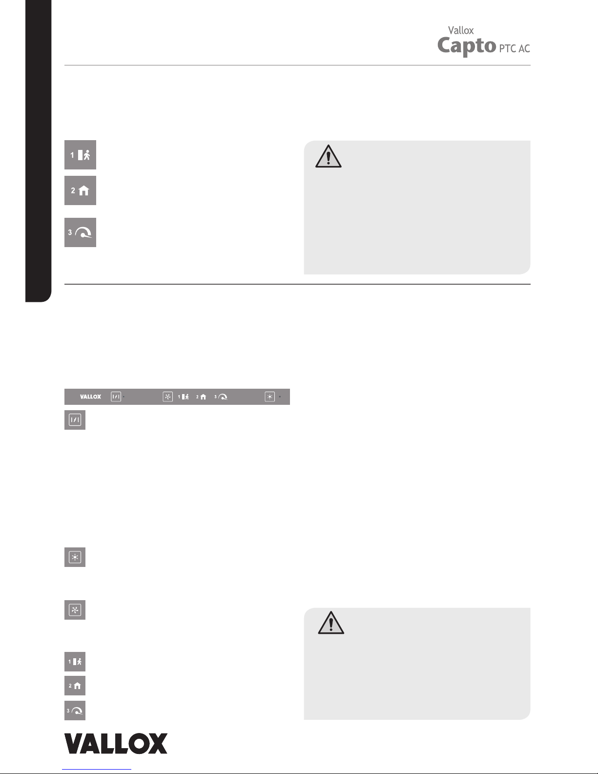
Front panel buttons
The front panel of the cooker hood has two buttons.
Position of the damper
In normal circumstances, the damper must be closed
(the signal light is o), which boosts the extract air flow
from other premises.
The damper must be open (the signal light is turned on)
when the user wants to increase the extract air flow from
the cooker hood e.g.
• when the cooker top or the oven is used for cooking;
• the load in the kitchen is exceptional due to the use
of strong detergents, presence of a large number of
people, or similar.
Cooker hood light
Turn the light on or o by pressing the light switch. The light
is dimmable. Adjust the brightness by pressing the light
switch until the brightness is adequate.
Ventilation profiles
Select the profile by pressing the ventilation profile button
repeatedly until the signal light indicates the desired
ventilation profile.
Away profile
At home profile
Boost profile
1. Away profile
The ventilation eciency can be temporarily
reduced when the apartment is unoccupied.
Other functions
Guard function
The cooker hood is equipped with a guard function that is
activated when the temperature of the cooker hood exceeds
60°C or af ter a sudden increase in temperature (> 8°C/min).
In such a case, all signal lights of the cooker hood and the
LED light will flash. If this kind of alarm is noticed before fire
damage, it can be acknowledged by pressing any of the
cooker hood buttons.
Pre-selection of light brightness
The hood has a button for adjusting the brightness of the
light. The location of the button is not marked on the front
panel but can be found roughly 2 cm to the left of the light
switch.
To modify the pre-selection of light brightness:
1. Turn on the light, close the damper, and set the
ventilation to the Away profile.
2. Press the selection button for roughly 3 seconds until
the setting mode signal light starts to flash.
3. Adjust the brightness of the light by pressing the light
button until the brightness is adequate.
4. To save the setting, press the selection button for
roughly 3 seconds until the setting mode signal light
stops to flash.
To read about the other functions of the selection button, go
to our website, www.vallox.com.
2. At home profile
Ventilation must be continuous, i.e. the air
inside the building must be replaced at least
once every two hours.
3. Boost profile
Cooking, sauna, bathing, drying of clothes,
excessive heat, and other similar situations
can require that ventilation be increased
from the standard setting. In such a situation,
ventilation must be increased.
PLEASE NOTE!
• Neglecting the cleaning of the grease filter can cause a
fire hazard.
• The outer surfaces of the hood can become hot when the
cooker or the oven is turned on.
• Flaming is forbidden underneath the cooker hood.
• Always follow the instructions provided on adjusting the
eciency of ventilation.
• Enable a sucient supply airflow into the room if
the cooker hood and non- electric devices are used
simultaneously.
WARNING!
The unit is not intended for use by children under 8 or
by persons with reduced sensory, physical or mental
capabilities, or whose lack of knowledge and experience do
not ensure safe operation of the unit. Such persons can use
the unit under supervision, or by following the instructions
of someone who is responsible for their safet y. Do not let
children play with the unit or to clean or maintain it without
supervision.
Page 3

3
© Vallox Oy - All rights reserved
MANUAL
MAINTENANCE
Keep the cooker hood clean. Wipe outer surfaces regularly
with water containing a small amount of a mild detergent.
Clean o any grease stains immediately. Do not use abrasive
or corrosive detergents or tools.
Keep the grease filter clean to ensure an adequate extract air
flow. The grease filter must be washed with warm water and
detergent at least 1-2 times a month.
Light
The cooker hood has a long-lasting LED lighting module. If
the light is not working, contact a servicing company.
Removing and mounting the grease filter
Removing the filter Mounting the filter
INSTALLATION
In the example, the bottom of the sides and the rear of the
hood are level with the bottom of the top cabinets (see
figures 1-2). In this case, a specially made cover panel is
needed to hide the hood. The height of the cover panel is
roughly 210 mm.
The hood can also be installed higher, even so that it touches
the frame of the spice cabinet. In this case, rear corners need
to be sawn o from the spice cabinet frame (see figure 3). In
this mounting method, the height of the hood cover panel is
100 mm.
When the lowest possible mounting height is used, the
bottom edge of the sliding glass, when pushed inside the
hood, is level with the bottom of the top cabinet frames
(see figure 4). The L strip is mounted on the wall as shown
in figure 5. In this mounting method, the height of the hood
cover panel is roughly 248 mm.
Figure 1.
Remove the spice cabinet. Mount the L strip on the wall so
that it is level.
The L strip fully covers the gap between the hood and the
wall and also makes it easier to balance the hood in place
during mounting.
If the top cabinet frames are less than 305 mm deep, the
longer edge of the L strip is mounted on the wall. The
perforations on the lower surface of the L strip can be
covered using white plastic studs.
• Pull the locking device of the grease filter towards the
front edge of the cooker hood while pulling the grease
filter downwards until it comes o.
• Wash the grease filter and leave to dry.
• Mount the grease filter back in place. Push the front
edge of the filter into the pins on the cooker hood, and
click the rear edge in place.
NOTE! Ensure that the locking device points
downwards.
PLEASE NOTE!
• The cooker hood must not be connected to a flue that is
used for removing combustion gases (e.g. from a wood- or
gas-burning fireplace, cooker, or stove).
• Fans that are controlled through the cooker hood must
have an engine cover and their maximum power is 340 W.
• Regulations on leading extraction air outdoors must be
observed.
PLEASE NOTE!
The minimum distance of the bottom edge of the hood
to an electric cooker is 426 mm and to a gas cooker
650 mm.
Figure 2.
Place the hood on top of the L strip so that it is level and
fasten the hood on the top cabinet frames with four screws. It
is vital that the hood is both vertically and horizontally level.
The front panel of the hood must be at the same depth as the
outer surface of the top cabinet doors.
Figure 3.
If the highest possible mounting height is used, saw o
diagonal pieces measuring at least 20x50 mm from the spice
cabinet frame.
Figure 4.
The hood when the lowest possible mounting height is used.
Figure 5.
Location of the L strip when the lowest hood mounting height
is used.
1
2
4
38 mm
5
min. 426mm /
650mm
3
50mm
20mm
PLEASE NOTE!
• The power outlet used for the cooker fan must be
easy to access.
Page 4

MANUAL
D3927/9.5.2017
External electrical connection to a roof fan
SPEED SWITCH
MOTHERBOARD
OF THE PTC AC HOOD
S1 S2 S3 out
N
N
L
E.g. Vallox 95/75 Distribution board
Opening the door of a Vallox ventilation unit
Cuts power supply to the cooker hood.
If the cooker hood has been connected
to some other device, a switch must
be added in the immediate vicinity
of the hood that cuts power supply
to both N and L.
NOTE!
Do not connect
the power cord
L
N
90V, 110V, 120V, 160V
L 230V
L 230V
135V
70V
and 180V (free)
TRANSFORMER
Underneath the lid
of the left electric box
N N N
L L
L1
L
N
10A
1 2 3
L1
External electrical connection to the ventilation unit
As the default factory setting, the
following voltages have been set for the
cooker hood:
• Away profile 70V
• At home profile 135V
• Boost profile 230V
To change these values, move the
transformer wires to more suitable
connectors (see the wiring diagrams).
SPEEDSWITCH
S1 S2 S3 out
MOTHERBOARD
OF THE PTC AC HOOD
AC-fan
and 180V (free)
TRANSFORMER
Underneath the lid
of the left electric box
SETTING THE
VENTILATION
PROFILE
Measuring and adjusting performance values
Standard ventilation
The volume flow rate of the air inside the cooker hood is measured
with the damper closed and, where required, adjusted based on the
static pressure loss and the performance scheme of the cooker hood.
• The static pressure loss is measured from the hole in the damper
using the measuring tube found in the accessory bag (see figure).
• Determine the volume flow rate from
the performance scheme based
on the measured pressure and the
number of open holes in the damper.
Adjustment:
• Cover the required number of holes
in the damper with the magnetic
strip that is delivered with the cooker
hood.
dp
Boost ventilation
The volume flow rate of the air inside
the cooker hood is measured with
the damper open based on the static
pressure loss and the performance
scheme of the cooker hood.
• Measure the static pressure
loss of the cooker hood. The
measuring point must be located 2
times the duct diameter above the
outlet collar of the cooker hood
(see figure).
• Determine the volume air flow based on the measured pressure
and the performance scheme (with the damper open).
2 3 4 5 6 7 8 9 10 20 30 40 50 60 70
20
30
40
50
60
70
80
90
200
300
400
10
100
45
40
35
30
25
45
40
35
30
25
LpA, dB(A)
74 6532 8
Airflow, dm³/s
Static pressure loss Pa
Damper open
Adjustment position
2 = 20 holes open
3 = 30 holes open
4 = 40 holes open
5 = 50 holes open
6 = 60 holes open
7 = 70 holes open
8 = 80 holes open
Standard ventilation (settings 2-8)
Vallox Oy | Myllykyläntie 9-11 | 32200 LOIMA A | FINLAND
www.vallox.com | Exchange +358 10 7732 200 | Aftersales +358 10 7732 270
dp
Measuring point,
min. 2 x du ct diam eter
 Loading...