

Vallox TSK Multi 80 MV EHX, TSK Multi 50 MV EH, TSK Multi 80 MV, TSK Multi 80 MV EH, 90 MV User Manual
...Page 1
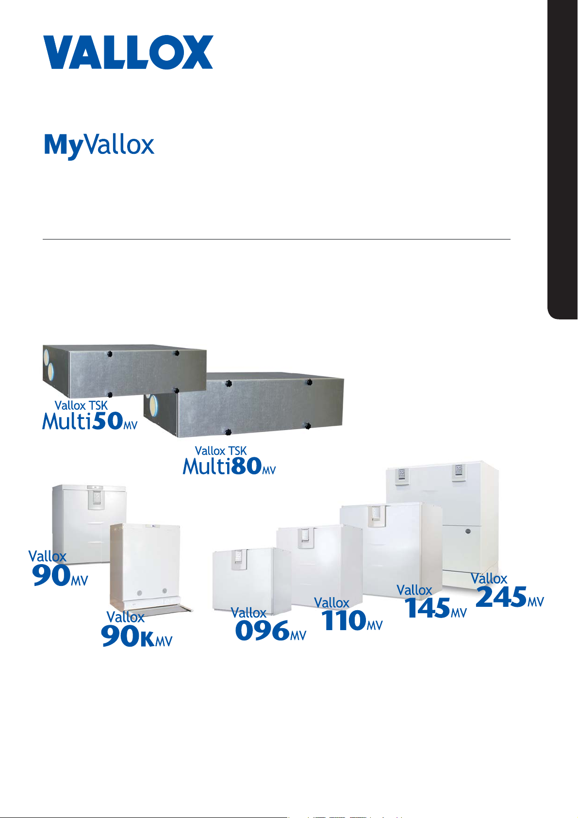
Manual
Model
Vallox TSK Multi 50 MV
Vallox TSK Multi 50 MV EH
Vallox TSK Multi 80 MV
Vallox TSK Multi 80 MV EH
Vallox TSK Multi 80 MV EHX
Vallox 90 MV
Vallox 90K MV
Vallox 096 MV
Vallox 110 MV
Vallox 145 MV
Vallox 245 MV
Vallox 245 MV VKL
Document
MANUAL
D3768
Valid from
3.2.2015
Updated
7.6.2017
Ventilation units
Page 2
INTRODUCTION
SAFETY
Safe and appropriate handling requires knowledge of the basic
safety regulations, and of the intended use of the ventilation
system. Read this manual before operating the ventilation unit.
Retain the manual for later reference. If you lose the manual, it can
be downloaded from our website.
This user manual contains all the information necessary for safe
operation of the system. All persons who operate and maintain
the ventilation system must follow the instructions provided in this
manual. Furthermore, all local accident prevention regulations must
be observed.
Installation
Installation and setup should be carried out only by qualified
experts. Electrical installations and connections must be carried
out only by an electrician and in compliance with local regulations.
GUARANTEE
The guarantee and liability exclude damage resulting from:
• Inappropriate use of the ventilation system or the control unit
• Incorrect or inappropriate installation, setup or use
• Neglect of instructions concerning transportation, installation,
use, or maintenance
• Structural or electronic modifications or changes made to the
software
NOTE
For further information,
go to www.vallox.com
WARNING
The unit is not intended for
use by children under 8 or by
persons with reduced sensory,
physical or mental capabilities,
or whose lack of knowledge
and experience do not ensure
safe operation of the unit.
Such persons can use the
unit under supervision, or by
following the instructions of
someone who is responsible for
their safety.
INTENDED USE
All Vallox ventilation units have been designed to provide
appropriate and continuous ventilation so as to present no threat to
health and to maintain structures in good condition.
IMPORTANT
In order to ensure that the indoor air presents no harm to
health and remains optimal also for the structures of the
building, ventilation must be kept on without disruptions. It
is recommended that ventilation be left turned on during long
holidays also. This keeps the indoor air fresh and prevents humidity
from condensing in the ventilation ducts and structures. It also
reduces the risk of moisture damage.
DISPOSAL OF THE VENTILATION UNIT
Do not dispose of electronic devices with household waste. Follow
local laws and regulations on safe and ecological disposal of the
product.
4
Page 3

INTRODUCTION
MAIN PARTS
VALLOX TSK MULTI 50 MV AND
VALLOX TSK MULTI 80 MV
F
I
C
F
E
I
E
L
N
A
+
C
Y
R
A
T
I
N
G
O
F
E
X
T
R
A
C
T
O
A
I
R
C
H
E
E
R
A
T
A
A
Y
U
N
N
R
E
V
3
1
9
Supply air fan
Extract air fan
7
6
4
5
8
2
R model in the
figure
10
11
Bypass flap
1
Safety switch
2
12
8
9
Post-heating radiator
Heat recovery cell
Supply air filter F7
Supply air filter G4
Extract air filter G4
Control panel
3
10
Carbon dioxide sensor
4
11
Humidity sensor
5
12
6
7
6
Page 4

INSTALLATION
GENERAL INSTALLATION INSTRUCTIONS
INSTALLATION SITE
The Vallox ventilation unit must be installed in a
location where the temperature remains above
+10°C. When the unit is installed without a protective
enclosure, the location must be chosen so that its
noise does not cause any disturbance (e.g. storage
premises, technical spaces, and false ceilings).
CONDENSING WATER
The unit is delivered with a water seal that has an air
lock and a more compact elbow. When the elbow is
used, an air lock must be installed somewhere else
between the extraction pipes (the parts needed are
included in the accessory bag). The air lock ensures
the removal of condensing water and mues any
noise.
WARNING
Water must at all times be kept
out of the electrical system.
50
Page 5

INSTALLATION SITE
Vallox TSK Multi 50 MV and Vallox TSK Multi 80 MV
must be mounted on the ceiling. Use the mounting
hooks (4 pcs) delivered with the unit to mount the
ventilation unit on the ceiling. Observe the weight of
the unit (45 kg / 58.5 kg) when mounting.
IMPORTANT
The unit must be installed straight so that the
condensing water that collects in the bottom pool
drains through the condensing water outlet.
NOTE
Reserve a space equal to the depth of the unit in front
of the unit for servicing purposes.
INSTALLATION
NOTE
The whole length of the outdoor air duct to the unit
and exhaust air duct from the unit must be insulated
using closed cell insulation.
MEASURING TUBES
The accessories delivered with the unit include four
air flow measuring tubes. These can be inserted in the
ducts to allow for easier ventilation adjustment.
a
a
51
© Vallox Oy - All rights reserved
Page 6

INSTALLATION
DIMENSIONS AND DUCT OUTLETS
UNIT DIMENSIONS
Dimension Vallox TSK
Multi 50 MV
A900 1026
B547 626
C236 293
D 100 (female) 125 (female)
E87 110
F197 254
G86 110
H161 200
I161 200
J86 96
K96 96
L206 231
M498 624
N View from right
O View from above
P View from left
QRight side
RLeft side
S Seen from behind
Vallox TSK
Multi 80 MV
R model:
1. Outdoor air to the unit
2. Supply air from the unit to the
3. Extract air from the apartment to
4. Exhaust air flowing outdoors
A
N
B
4
G
H
apartment
the unit
from the unit
NOTE
Fold the temperature sensor
holder if the supply air duct at the
rear of the unit is used. Ensure
that the sensor cable is not in
contact with the heater.
4
1
C
Q
1
4
1
I
4
J
K
L
O
1
S
D (Ø)
P
2
R
3
2
3
3
2
J
K
L
L model:
1. Extract air from the apartment
to the unit
2. Exhaust air flowing outdoors
from the unit
3. Outdoor air to the unit
4. Supply air from the unit to the
apartment
2
3
I
F
E
UNIT DIMENSIONS
Dimension TSK Multi
50 MV
A431 519
B91 91
C16 16
D 548 626
E530 600
F236 293
G935 1060
H900 1026
IService space
JPower plug cord
KWater seal
L Alternative water seal
M Space required for installation
TSK Multi
80 MV
D
E
B A
I
C
70
43
K
M
J
G
F
I
H
L
28
47
54
52
 Loading...