

Page 1

VFlex Corner Sequencing
Control Panel
Owner's Manual
0999114_B
© 2018 Valmont Industries, Inc., Valley, NE 68064 USA. All rights reserved.
www.valleyirrigation.com
Page 2

2
Page 3

Table of Contents
VFlex Corner Sequencing Control Panel Owner's Manual ........................................................................... 1
Table of Contents ............................................................................................................................................. 3
EC Declaration of Conformity.......................................................................................................................... 5
Electrical Safety Statement ............................................................................................................................. 6
Installation Of The Valley Electric Irrigation Machine - European Union Only ............................................ 6
About This Manual ........................................................................................................................................... 6
Ancillary Equipment Warranty ........................................................................................................................ 6
Safety ................................................................................................................................................................. 7
Recognize Safety Information............................................................................................................................. 7
Safety Messages ........................................................................................................................................... 7
Information Messages ................................................................................................................................... 7
Use Of Personal Protective Equipment .............................................................................................................. 8
Conductive Materials And Equipment ................................................................................................................ 8
Fall Protection ..................................................................................................................................................... 8
Minimum Working Clearance .............................................................................................................................. 9
Qualified Person ................................................................................................................................................. 9
Overhead Power Lines ..................................................................................................................................... 10
Minimal Lockout / Tagout Procedure................................................................................................................. 11
Sequence Of Lockout .................................................................................................................................. 11
Restoring Equipment To Service ................................................................................................................. 11
Safety ............................................................................................................................................................... 12
Operate Safely .................................................................................................................................................. 12
Safety Decals ................................................................................................................................................... 14
Overview .......................................................................................................................................................... 17
VCS Control Panel ........................................................................................................................................... 17
Term Definitions: .......................................................................................................................................... 17
Corner Identification ......................................................................................................................................... 18
Standard (Trailing) Corner ................................................................................................................................ 18
Inverted (Leading) Corner ................................................................................................................................ 18
Main Status Menu ............................................................................................................................................. 19
Time ............................................................................................................................................................ 19
Corner Angle (CANGLE) ............................................................................................................................. 19
Error Code (Exx) ......................................................................................................................................... 19
Speed .......................................................................................................................................................... 19
Date ............................................................................................................................................................. 19
Machine Angle (MANGLE) .......................................................................................................................... 19
Adjusted Speed ........................................................................................................................................... 19
SOL# ........................................................................................................................................................... 19
TEN+ ........................................................................................................................................................... 19
Function Keys ................................................................................................................................................... 20
Home Key .................................................................................................................................................... 20
Diagnostics Key ........................................................................................................................................... 20
Program Key ............................................................................................................................................... 20
Options Key ................................................................................................................................................. 20
Pressure ...................................................................................................................................................... 20
Direction ...................................................................................................................................................... 20
End Gun (EG) .............................................................................................................................................. 20
Solenoid Numbers ....................................................................................................................................... 20
Modes .......................................................................................................................................................... 20
Numeric Entry Keys .......................................................................................................................................... 21
Decimal Point Key ....................................................................................................................................... 21
Minus Sign Key ............................................................................................................................................ 21
Escape Key ................................................................................................................................................. 21
Number Keys ............................................................................................................................................... 21
3
Page 4

Table of Contents
Navigation Arrow Keys ................................................................................................................................ 21
Up Arrow Key ............................................................................................................................................ 21
Left Arrow Key .......................................................................................................................................... 21
Right Arrow Key ........................................................................................................................................ 21
Down Arrow Key ....................................................................................................................................... 21
Enter Key ..................................................................................................................................................... 21
Symbols and Conventions ................................................................................................................................ 22
Command Prompt ....................................................................................................................................... 22
Exiting Screens ........................................................................................................................................... 22
Screen Delays ............................................................................................................................................. 22
Illustrations .................................................................................................................................................. 22
Operation ......................................................................................................................................................... 23
Starting the VFlex Sequencing Control Panel .................................................................................................. 23
Corner Applications ..................................................................................................................................... 23
Boot Splash Screen ..................................................................................................................................... 23
VCS Computer Boot Up Screen .................................................................................................................. 23
Acquiring Satellites Screen ......................................................................................................................... 23
Programs Key ................................................................................................................................................... 24
Irr/Chem ...................................................................................................................................................... 24
Seq Overrides ............................................................................................................................................. 24
Crnr Angle ................................................................................................................................................ 24
Position ..................................................................................................................................................... 24
Corner Angles ........................................................................................................................................... 25
Machine Angles ........................................................................................................................................ 26
Retracted Psi ............................................................................................................................................ 27
Diagnostics ..................................................................................................................................................... 29
Diagnostics Screen ........................................................................................................................................... 29
System Faults .............................................................................................................................................. 29
Viewing System Faults .............................................................................................................................. 29
Status Screen Diagnostics .......................................................................................................................... 29
Error Code Summary .................................................................................................................................. 30
Error Logs .................................................................................................................................................... 31
Viewing An Error Log .................................................................................................................................. 31
Resetting An Error Log To Zero ................................................................................................................... 31
System Review Log .......................................................................................................................................... 32
Reviewing Status Changes and Errors ........................................................................................................ 32
IO ...................................................................................................................................................................... 33
A/D - Analog to Digital Voltages .................................................................................................................. 33
Reviewing A/D .......................................................................................................................................... 33
Modules ....................................................................................................................................................... 34
Reviewing Modules ................................................................................................................................... 34
GPS ............................................................................................................................................................. 34
Reviewing GPS ......................................................................................................................................... 34
Troubleshooting .............................................................................................................................................. 35
System Faults ................................................................................................................................................... 36
Error Codes ...................................................................................................................................................... 36
Troubleshooting List ......................................................................................................................................... 38
Hard Reset ....................................................................................................................................................... 38
Executing A Hard Reset .............................................................................................................................. 38
4
Page 5

EC Declaration of Conformity
We: Valmont Industries, Inc.
28800 Ida Street
Valley, NE 68064
+1 402.359.6312
+1 402.359.6143 (Facsimile)
declare under our sole responsibility that the product,
Crop Irrigation System
to which this documentation relates, is in conformity with the following documents:
Machinery Directive 2006/42/EC
Low Voltage Directive 2014/35/EU
Electromagnetic Compatibility Directive 2014/30/EU
The above-referenced equipment is in conformity with all safety-related clauses (Not all clauses reflecting
commercial preference are met) of the following documents:
EN 60204-1:2006 Safety of Machinery – Electrical Equipment of Machines
EN 12100:2010 Safety of Machinery
EN 909:1998+A1 Irrigation Machines
Statement regarding Pressure Equipment Directive 97/23/EC:
Serial Number:
Purchase Order:
The Crop Irrigation System is excluded from the scope of the Pressure Equipment Directive, by the
language of Article 1, Sections 3.2, 3.6 & 3.10. This equipment is classified less than Category 1.
Statement regarding RoHS Directive 2011/65/EC:
The Crop Irrigation System is excluded from the scope of the RoHS Directive, by the language of Article
2, Section 4(e), being a “Large Scale Fixed Installation.”
Person Authorized to Compile the Technical File in Europe: Philipp Schmidt-Holzmann
Relevant information will be transmitted via e-mail Valmont S.A.U.
in response to a reasoned request by national authorities 28840 Mejorada del Campo
Madrid, ES 28840
+34 91 679 4300
Ron Pollak Date of Issue: March 9, 2018
Senior Electrical Engineer Place of Issue: Valley, NE 68064
Valmont Industries, Inc.
5
Page 6

Electrical Safety Statement
Installation Of The Valley Electric Irrigation Machine - European Union Only
Valmont Industries Inc. does not install a differential (ground fault) circuit breaker in the control panel of the
Valley electric irrigation machine because the standards of protection vary according to country of destination.
The distributor must provide and install a differential (ground fault) circuit breaker that meets the standards of
the country where the Valley irrigation machine is installed.
In the European Union, differential circuit breaker protection is fixed at a maximum of 24 volts.
Good grounding of the Valley irrigation machine is required.
• If resistance to ground is lower than 80 ohms, a differential (ground fault) circuit breaker of 300 mA will meet
requirements.
• If resistance to ground is between 80 and 800 ohms, a differential (ground fault) circuit breaker of 30 mA will
meet requirements.
The power supply installation and inspection of equipment protection components or machines are the
responsibility of the installer. Valmont Industries Inc. Is not responsible for the failure of equipment protection
components or machine not of their manufacture.
Valley pivot irrigation machines receiving power from a generator must have a cable connected from the
irrigation machine structure to a ground rod and another cable from the irrigation machine structure to the
ground terminal on generator in order for the differential (ground fault) circuit breaker to work.
• The resistance between the irrigation machine and the generator must be substantially below 80 ohms.
About This Manual
Information contained in this manual applies to the VFlex Corner Sequencing (VCS) Control Panel with software
version 1.01.
For proper operation of the irrigation machine, the VCS Control Panel Owner’s Manual, the machine Control
Panel Owner’s Manual and Irrigation Machine Owner’s Manual must be used together.
The Control Panel Owner’s Manual includes safety guidelines and explains the basic operation of the machine
control panel itself.
The Irrigation Machine Owner’s Manual includes safety guidelines and explains the operation of the irrigation
machine.
All owner’s, operators and maintenance personnel MUST read and understand the VCS Control Panel Owner’s
Manual, the machine Control Panel Owner’s Manual and Irrigation Machine Owner’s Manual.
Specifications, descriptions and illustrative material contained herein were as accurate as known at the time
this publication was approved for printing. Valmont Industries Inc., reserves the right to change specification or
design without incurring obligation. Specifications are applicable to machines sold in the United States and may
vary outside the United States.
Ancillary Equipment Warranty
The owner is responsible for warranty registration of all ancillary equipment such as engines, pumps and
generators with its respective manufacturer.
6
Page 7
Safety
Recognize Safety Information
This irrigation equipment may be powered by high voltage which can be extremely dangerous if used improperly. For maximum safety and optimum performance of the machine, all owners operators and maintenance
personnel must read and understand the owner/operator manual(s), all safety messages in this manual and
safety signs/decals on the machine before operating this equipment.
Anyone assembling, operating, servicing or maintaining this machine must read and understand all operation, maintenance, troubleshooting, testing, installation, assembly instructions and all safety messages in this
manual before operating the machine or beginning any maintenance, troubleshooting, testing, installation or
assembly of components.
These instructions alert you to certain things you should do carefully; if you don’t, you could hurt yourself or
others, hurt the next person who operates the equipment, or damage the equipment.
Safety Messages
Safety messages in this manual are preceded by the hazard symbol and one of three words, danger, warning
or caution. These messages alert you to potential hazards that could hurt you or others and or cause property
damage.
This HAZARD SYMBOL is used to alert you to information about unsafe actions or situations, and may
!
be followed by the word danger, warning, or caution.
!
DANGER
The HAZARD SYMBOL used with the word DANGER, will describe immediate hazards that may result in
severe personal injury or death.
!
WARNING
The HAZARD SYMBOL used with the word WARNING, will describe unsafe actions or situations that may
cause severe injury, death and/or major equipment or property damage.
!
CAUTION
The HAZARD SYMBOL used with the word CAUTION, will describe unsafe actions or situations that may cause
injury, and/or minor equipment or property damage.
Information Messages
Important information messages in this manual are preceded by the word NOTE.
NOTE
The word NOTE is used to alert you to information that describes procedures or tips to help you install, operate
or maintain your equipment properly.
7
Page 8

Safety
Use Of Personal Protective Equipment
• People working in areas where there are potential electrical hazards must use, personal protective equipment that is appropriate for the specific parts of the body to be protected and for the work to be performed.
Refer to U.S. Occupational Safety & Health Administration (OSHA) Regulations (Standards - 29 CFR) Safeguards for personnel protection. - 1910.335, or applicable national, state or local regulations, for additional
information.
• Personal protective equipment must be maintained in a safe, reliable condition and periodically inspected or
tested.
• Protective shields, protective barriers, or insulating materials must be used to protect each person from
shock, burns, or other electrically related injuries while that person is working near exposed energized parts
which might be accidentally contacted or where dangerous electric heating or arcing might occur. When normally enclosed live parts are exposed for maintenance or repair, they must be guarded to protect unqualified
persons from contact with the live parts.
• Safety signs and tags. Safety signs, safety symbols, or accident prevention tags must be used where necessary to warn people about electrical hazards which may endanger them.
Conductive Materials And Equipment
Materials and equipment that may conduct electricity must be handled in a way that will prevent them from
contacting energized power lines, exposed conductors or circuit parts.
• When handling long conductive objects (such as but not limited to truss rods, pipes, angles and ladders) in
areas with energized power lines, exposed conductors or circuit parts, work practices (such as the use of
insulation, guarding, and material handling techniques) must be used to minimize the hazard.
• Portable ladders must have non-conductive side rails.
• Do not wear conductive articles of jewelry and clothing (such as but not limited to watch bands, bracelets,
rings, key chains, necklaces, metalized aprons, cloth with conductive thread, or metal headgear) that could
come in contact with energized power lines, exposed conductors or circuit parts.
Fall Protection
Identify potential fall hazards and determine if fall protection equipment is appropriate for the task, before beginning the work. Pay attention to hazards associated with routine and non-routine tasks. Inspect fall protection
equipment (harnesses, lanyards) and devices (guardrails, tie-off points) before each use. Use fall protection
equipment if required for the job. Be sure the fall protection equipment is right for the task, fits properly, and is in
good condition. Refer to U.S. Occupational Safety & Health Administration (OSHA) Regulations Standards - 29
CFR 1926.500, 1926.501 and 1926.502, or applicable national, state or local regulations for more information.
• When using scaffolds, make sure there is proper access, full planking, stable footing, and guard railing.
• When using a boom lift, keep feet firmly on the platform of a boom lift, use fall protection equipment tied-off
at all times to the guardrail or tie-off point.
• When using a ladder, make sure the ladder is non-conductive and the correct size for the task. Read the
ladder user instructions and be sure the ladder is in good condition. Make sure ladder is set on stable footing
and at the correct angle.
8
Page 9
Safety
Minimum Working Clearance
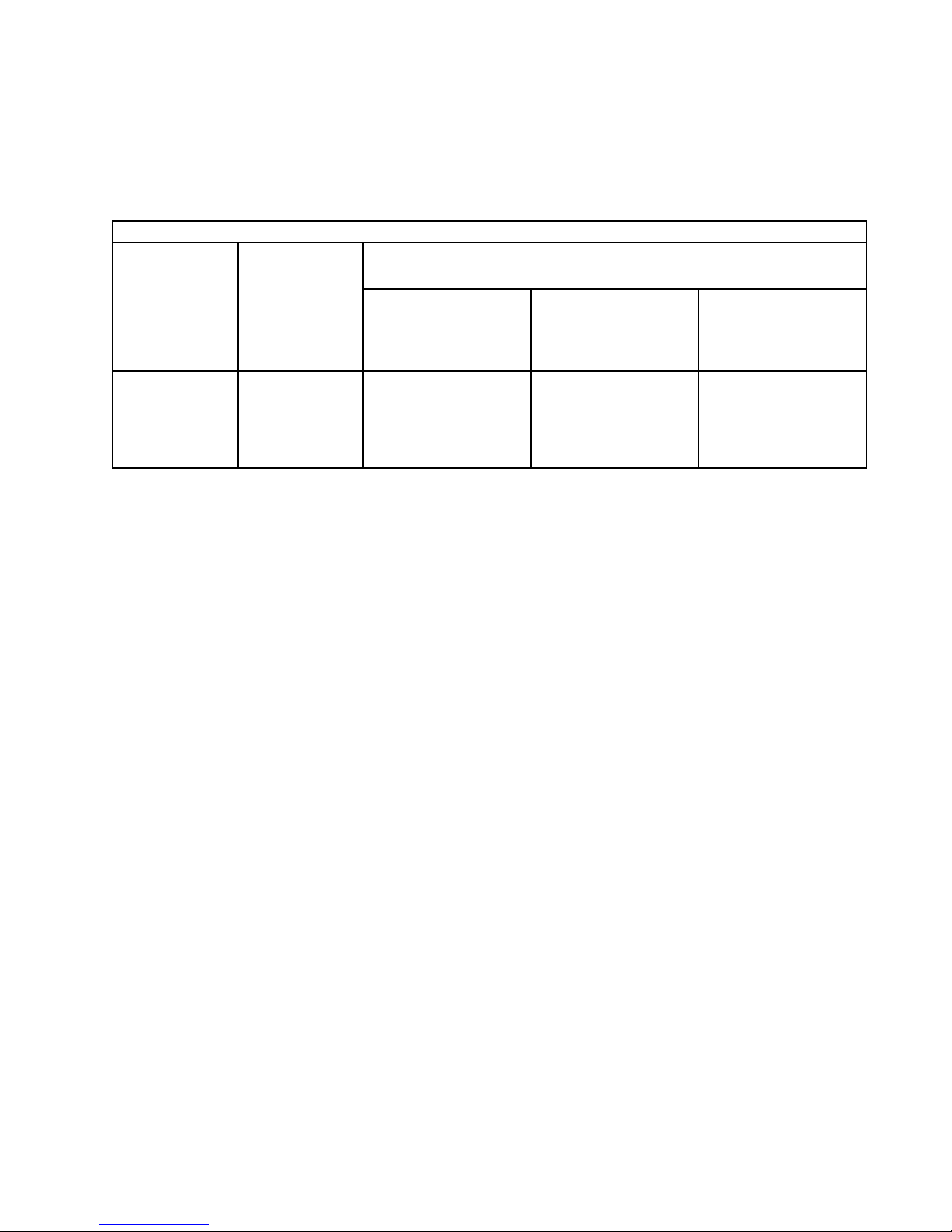
To reduce the risk of injury, all persons require adequate working clearance around the electrical panel or other
electrical equipment. The table below identifies the minimum working clearance needed. Refer to U.S. Occupational Safety & Health Administration (OSHA) Regulations (Standards - 29 CFR) Safeguards for personnel protection. -1910.303(g)(1)(i), or any other applicable national, state or local regulations, for additional information.
MINIMUM WORKING CLEARANCE 0-600 VOLTS
WIDTH
OF WORKING
CLEARANCE
AREA
30 in (760 mm)
MINIMUM OR
WIDTH OF
ENCLOSURE,
WHICH EVER IS
GREATER
Concrete, brick or tile walls shall be considered as grounded.
Qualified Person
A Qualified person is one who, by possession of a recognized degree, certificate, or professional standing, or
who by extensive knowledge, training, and experience, has successfully demonstrated his/her ability to solve or
resolve problems related to the subject matter, the work, or the project.
Only qualified persons may work on electric circuit parts or equipment that have not been de-energized.
Refer to U.S. Occupational Safety & Health Administration (OSHA) Regulations Standards - 29 CFR 1926.32(m)
and 1910.333, or applicable national, state or local regulations for additional information.
HEIGHT
OF WORKING
CLEARANCE
AREA
78 in (1980 mm)
MINIMUM OR
HEIGHT OF
ENCLOSURE,
WHICH EVER IS
GREATER
MINIMUM WORKING CLEARANCE
IN FRONT OF ELECTRICAL PANEL/EQUIPMENT
EXPOSED LIVE PARTS
ON ONE SIDE OF WORK
SPACE AND NO LIVE
GROUNDED PARTS ON
THE OTHER SIDE.
36 in (915 mm) MINIMUM 42 in (1065 mm) MINIMUM 48 in (1220 mm) MINIMUM
EXPOSED LIVE PARTS
ON ONE SIDE OF WORK
SPACE AND LIVE
GROUNDED PARTS ON
THE OTHER SIDE.
EXPOSED LIVE PARTS
ON ONE SIDE OF WORK
SPACE AND EXPOSED
LIVE PARTS ON THE
OTHER SIDE.
9
Page 10

Safety
Overhead Power Lines
Assembling, towing or transporting irrigation machine components such as but not limited to the pivot point,
linear cart, span/drive unit assemblies, overhangs and/or corner assemblies underneath or near power lines is
extremely dangerous because of the risk of electrocution.
Operating equipment that elevates irrigation machine components, such as but not limited to an aerial lift or
crane, near power lines is extremely dangerous because of the risk of electrocution. Only qualified personnel
should operate this type of equipment. Before operating the equipment, qualified personnel must read the
equipment manufacturers’ operating and safety instructions.
Refer to U.S. Occupational Safety & Health Administration (OSHA) Regulations (Standards - 29 CFR) Cranes
and derricks. - 1926.550, or any other applicable national, state or local regulations for additional information.
• Always presume that any overhead power line is an energized line unless and until the person(s) owning
the line and/or the electrical utility authorities indicate that it is not an energized line and it has been visibly
grounded.
• Before operating any equipment near any power line make sure the line has been de-energized and visibly
grounded at the point of work.
• Electrocution can occur without touching an electrical power line. Electricity, depending on the magnitude,
can jump or become induced into equipment or conductive materials that come in close proximity to, but do
not touch a power line. High wind, lightning, wet ground and other environmental conditions will increase the
possibility of electrocution and require additional consideration.
• Transmitter towers can induce the equipment or materials being handled with an electrical charge. Before
working or operating equipment near transmitter towers make sure the transmitter is de-energized.
• Select the location where the span/drive unit will be assembled to ensure that neither the irrigation machine,
or the equipment used during the assembly process, will violate the minimum clearance guidelines.
• Never operate equipment or allow the load, ropes or tag lines within 10 ft (3.05 m) of any power line rated 50
kV or lower whether it is energized or not. For lines rated over 50 kV, the minimum clearance shall be 10 ft
(3.05 m) plus 0.4 in (1.1 cm) for each kV over 50 kVs.
• Never assemble, tow, transport or allow irrigation machine components underneath or within 10 ft (3.05 m)
of any power line rated 50 kV or lower whether it is energized or not. For lines rated over 50 kV, the minimum
clearance shall be 10 ft (3.05 m) plus 0.4 in (1.1 cm) for each kV over 50 kVs. Overhang support angles,
cables and spinner drive components regularly extend 10 ft to 12 ft (3.1 m to 3.7 m) above the irrigation
pipeline (span).
• Use barricades to identify areas where interference with overhead power lines could occur. Keep the assembly, towing or transporting of irrigation machine components and the operation of equipment including load,
ropes or tag lines away from any power line, in the distances described above, whether the line is energized
or not.
• Always designate a person to observe clearance between the power line and all equipment being operated
or moved in order to give timely warning for all operations to STOP if the minimum clearance is violated.
10
Page 11
Safety
Minimal Lockout / Tagout Procedure
The following procedure establishes the minimum requirements for the lockout of energy isolating devices
whenever maintenance or servicing is done on machines or equipment. It is used to ensure that the machine
or equipment is stopped, isolated from all potentially hazardous energy sources and locked out before personnel perform any servicing or maintenance where the unexpectedly energized or start-up of the machine or
equipment or release of stored energy could cause injury. All personnel, upon observing a machine or piece of
equipment which is locked out to perform servicing or maintenance shall not attempt to start, energize, or use
that machine or equipment.
When the energy isolating devices are not lockable, tagout should be used and affected personnel must wear
full personal protection.
Refer to U.S. Occupational Safety & Health Administration (OSHA) Regulations (Standards - 29 CFR) Typical
minimal lockout procedures - 1910.147 App A, or applicable national, state or local regulations, for additional
information.
Sequence Of Lockout
1. Notify all affected personnel that servicing or maintenance is required on a machine or equipment and that
the machine or equipment must be shut down and locked out to perform the servicing or maintenance.
2. The authorized personnel shall identify the type and magnitude of the energy that the machine or equipment utilizes, shall understand the hazards of the energy, and shall know the methods to control the energy.
3. If the machine or equipment is operating, shut it down by the normal stopping procedure (depress the stop
button, open switch, close valve, etc.).
4. Deactivate the energy isolating device(s) so that the machine or equipment is isolated from the energy
source(s).
5. Lock out the energy isolating device(s) with assigned individual lock(s).
6. Stored or residual energy (such as that in capacitors, springs, elevated machine members, rotating flywheels, hydraulic systems, and air, gas, steam, or water pressure, etc.) must be dissipated or restrained by
methods such as grounding, repositioning, blocking, bleeding down, etc.
7. Ensure that the equipment is disconnected from the energy source(s) by first checking that no personnel
are exposed, then verify the isolation of the equipment by operating the push button or other normal operating control(s) or by testing to make certain the equipment will not operate. CAUTION: Return operating
control(s) to neutral or “off” position after verifying the isolation of the equipment.
8. The machine or equipment is now locked out.
!
DANGER
• WHEN PERSONNEL WILL BE EXPOSED TO CIRCUIT ELEMENTS AND ELECTRICAL PARTS, A
QUALIFIED PERSON MUST USE TEST EQUIPMENT TO VERIFY THAT THE CIRCUIT ELEMENTS AND
EQUIPMENT PARTS OF THE EQUIPMENT ARE DE-ENERGIZED.
Restoring Equipment To Service
When the servicing or maintenance is completed and the machine or equipment is ready to return to normal
operating condition, the following steps shall be taken.
1. Check the machine or equipment and the immediate area around the machine to ensure that nonessential
items have been removed and that the machine or equipment components are operationally intact.
2. Check the work area to ensure that all personnel have been safely positioned or removed from the area.
3. Verify that the controls are in neutral.
4. Remove the lockout devices and reenergize the machine or equipment.
5. Notify affected personnel that the servicing or maintenance is completed and the machine or equipment is
ready to be used.
11
Page 12
Safety
!
!
Operate Safely
Valley Irrigation machines are designed with safety in mind. However, if this machine is operated incorrectly,
it may pose a safety threat to the operator. A good safety program is much like a chain, it is only as strong
as its weakest link. The manufacturer, dealer, and operator must maintain and improve all safety programs.
Following is a list of safety operating tips which you and all other persons servicing or operating the machine
must read and understand:
CAUTION
• DO NOT operate this machine without first
reading the Owner’s Manuals for the machine.
• Read all safety messages in this manual and
safety signs on the machine.
• DO NOT let anyone operate this machine with-
out proper instructions.
• Unauthorized modifications may impair the
function and/or safety of the machine.
• If you do not understand any part of this manu-
al, contact your Valley dealer.
EMPLOYEE INSTRUCTION ON SAFETY
It is very important to instruct your employees on the
safe use of this equipment at the time of their initial
assignment to operate it. DO NOT let anyone operate
this equipment without proper instructions.
Safety training should be presented annually and
the service manager should ensure employees fully
understand the safety messages and what to do in
case of emergencies.
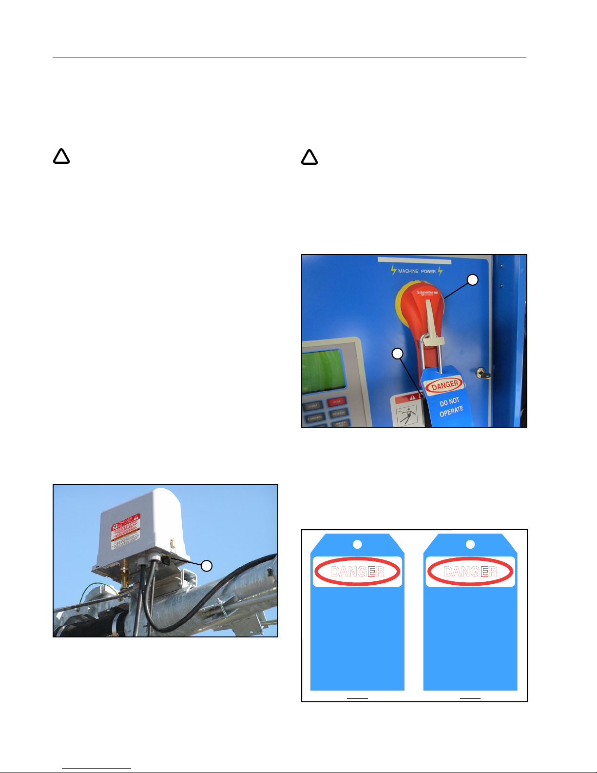
EMERGENCY STOPPING
The machine can be stopped at any time at any tower
by turning the disconnect switch, located underneath
the tower box, to the OFF position. See Figure 12-1.
DANGER
DISCONNECT POWER WHEN SERVICING
ALWAYS disconnect electrical power before
servicing or performing maintenance to the machine.
If you are going to perform maintenance on the
machine, YOU MUST shut off and lock the main
power disconnect as shown below. See Figure 12-2.
1
2
Figure 12-2 1 . Main Power Disconnect
2. Lock
The blue (OSHA safety color code) tag shown
below should also be filled out and attached to the
disconnect after locking. See Figure 12-3.
The tag should reveal the name of a person to contact
before restoring power to the machine.
Figure 12-1 1 . Disconnect Switch
12
1
Figure 12-3
DANGER
DO NOT
OPERATE
SIGNED BY:
DATE:
_ _ _ _ _ _ _ _ _ _ _ _ _ _ _ _ _ _ _ _ _ _ _ _ _ _ _ _ _ _ _ _ _ _ _ _
_ _ _ _ _ _ _ _ _ _ _ _ _ _ _ _ _ _ _ _ _ _ _ _ _ _ _ _ _ _ _ _ _ _ _ _
FRONT
0992009
DANGER
DO NOT REMOVE
THIS TAG
REMARKS:
_ _ _ _ _ _ _ _ _ _ _ _ _ _ _ _ _ _ _ _ _ _ _ _ _ _ _ _ _ _ _ _ _ _ _ _ _ _ _ _ _ _ _ _ _ _ _ _
_ _ _ _ _ _ _ _ _ _ _ _ _ _ _ _ _ _ _ _ _ _ _ _ _ _ _ _ _ _ _ _ _ _ _ _ _ _ _ _ _ _ _ _ _ _ _ _
_ _ _ _ _ _ _ _ _ _ _ _ _ _ _ _ _ _ _ _ _ _ _ _ _ _ _ _ _ _ _ _ _ _ _ _ _ _ _ _ _ _ _ _ _ _ _ _
_ _ _ _ _ _ _ _ _ _ _ _ _ _ _ _ _ _ _ _ _ _ _ _ _ _ _ _ _ _ _ _ _ _ _ _ _ _ _ _ _ _ _ _ _ _ _ _
_ _ _ _ _ _ _ _ _ _ _ _ _ _ _ _ _ _ _ _ _ _ _ _ _ _ _ _ _ _ _ _ _ _ _ _
SEE OTHER SIDE
BACK
Page 13
Safety
!
!
!
!
!
!
!
!
!
Operate Safely (Continued)
CAUTION
QUALIFIED SERVICE PERSONNEL
If you do not understand electricity or other parts
of the machine, have qualified service personnel
perform any hazardous repairs or maintenance.
CAUTION
GUARD ALL POWER TAKE-OFF DRIVES
This includes all belt and power line drives.
Replace any guards and shields removed for
maintenance.
WARNING
SUSPECTED SHORT CIRCUITS
DO NOT touch the machine if you suspect a shortcircuit situation. Call a qualified electrician or an
authorized Valley dealer immediately.
Circumstances which may cause you to suspect
hazardous voltage situations may include:
• Physical damage to the machine or span cable.
• Recent electrical storms (lightning).
• Unusual operating characteristics of the machine.
If you suspect a short circuit due to feeling a rippling
tingle when touching the machine, DO NOT touch
the machine again. Call a qualified electrician or an
authorized Valley dealer immediately.
WARNING
LIGHTNING AND THE MACHINE
Stay away from the machine during an electrical
storm. An irrigation machine makes a good path to
earth. It is also probably the tallest object in the field,
which makes it a good lightning receptor!
DANGER
DRIVE SHAFTS START WITHOUT WARNING
An electric motor on each tower of the center pivot
powers two drive shafts connected to wheel gear
drives. These drive shafts start and stop without
warning.
• DO NOT touch rotating drive shalt or shield, clothing or limbs may become entangled, resulting in
severe injury.
• DO NOT service the machine until the main disconnect is locked in the OFF position.
• ALWAYS replace drive shaft shields after servicing.
• DRIVE SHAFT SHIELDS MUST ALWAYS BE IN
PLACE WHEN OPERATING THE MACHINE.
CAUTION
CHECK WHEEL TRACKS BEFORE STARTING
Make sure all objects, livestock, or persons are
clear of the machine before starting. Drive trains are
powerful and can climb over vehicles, equipment,
etc.
CAUTION
KEEP CHILDREN AWAY
Irrigation machines are NOT playground equipment.
Prevent children from playing or climbing around
on the machine. This can be extremely dangerous,
especially if the machine is operating.
CAUTION
DO NOT OVERSIZE FUSES
Fuses are sized for the protection of a specific
machine.
Be certain you have the proper fuse sizes in place
before initial startup and when replacing fuses.
CAUTION
PLUG - IN CONNECTORS
Disconnect power before connecting or disconnecting
any plug-in connectors.
13
Page 14
Safety
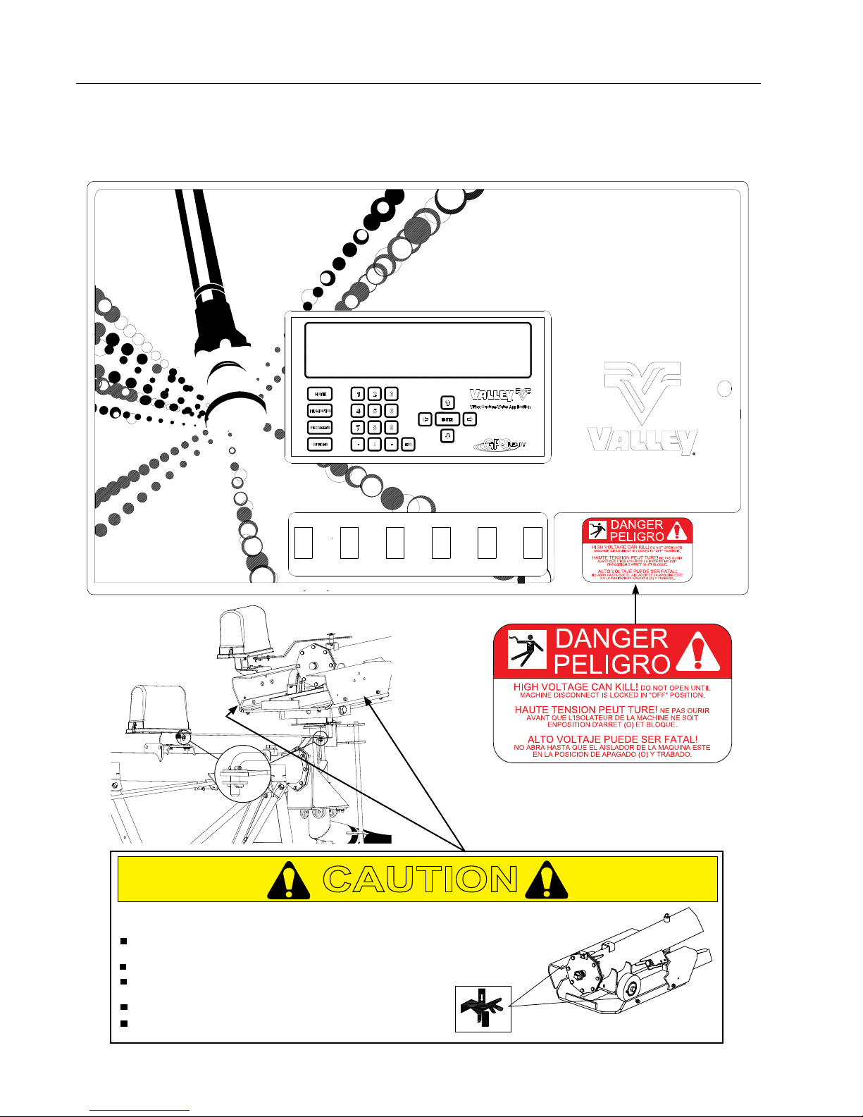
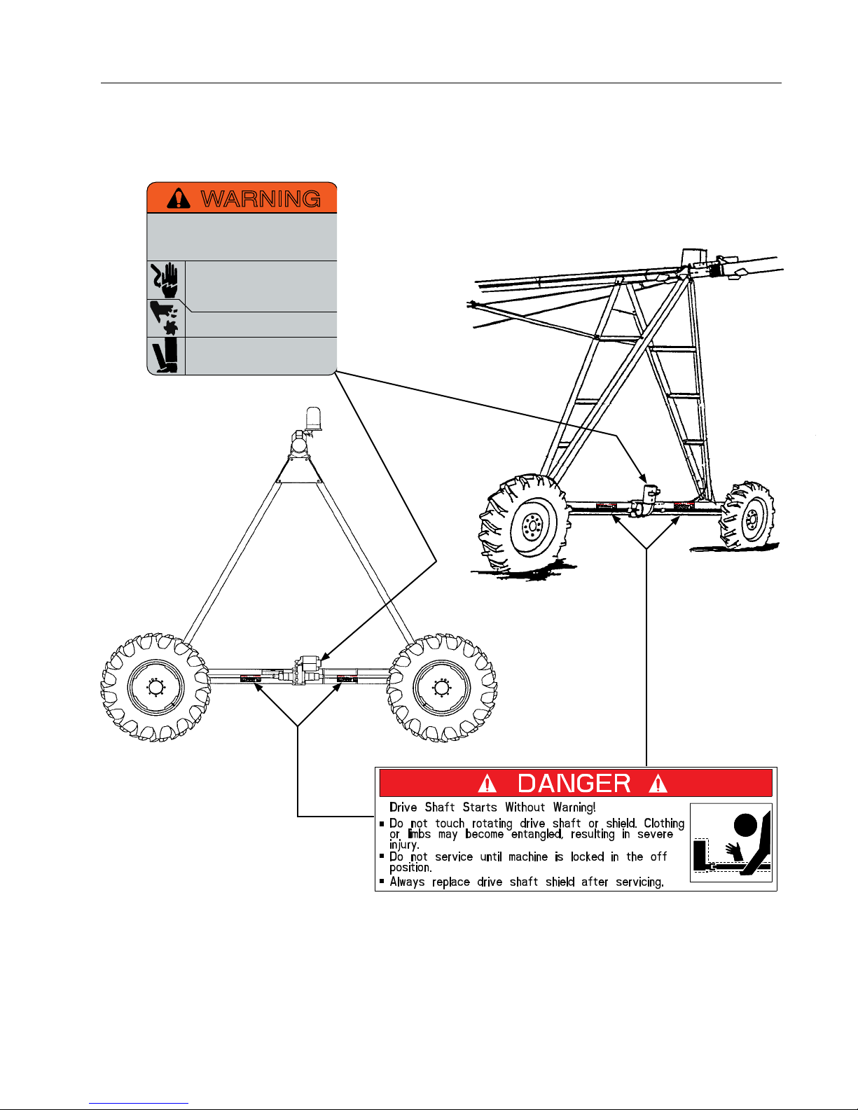
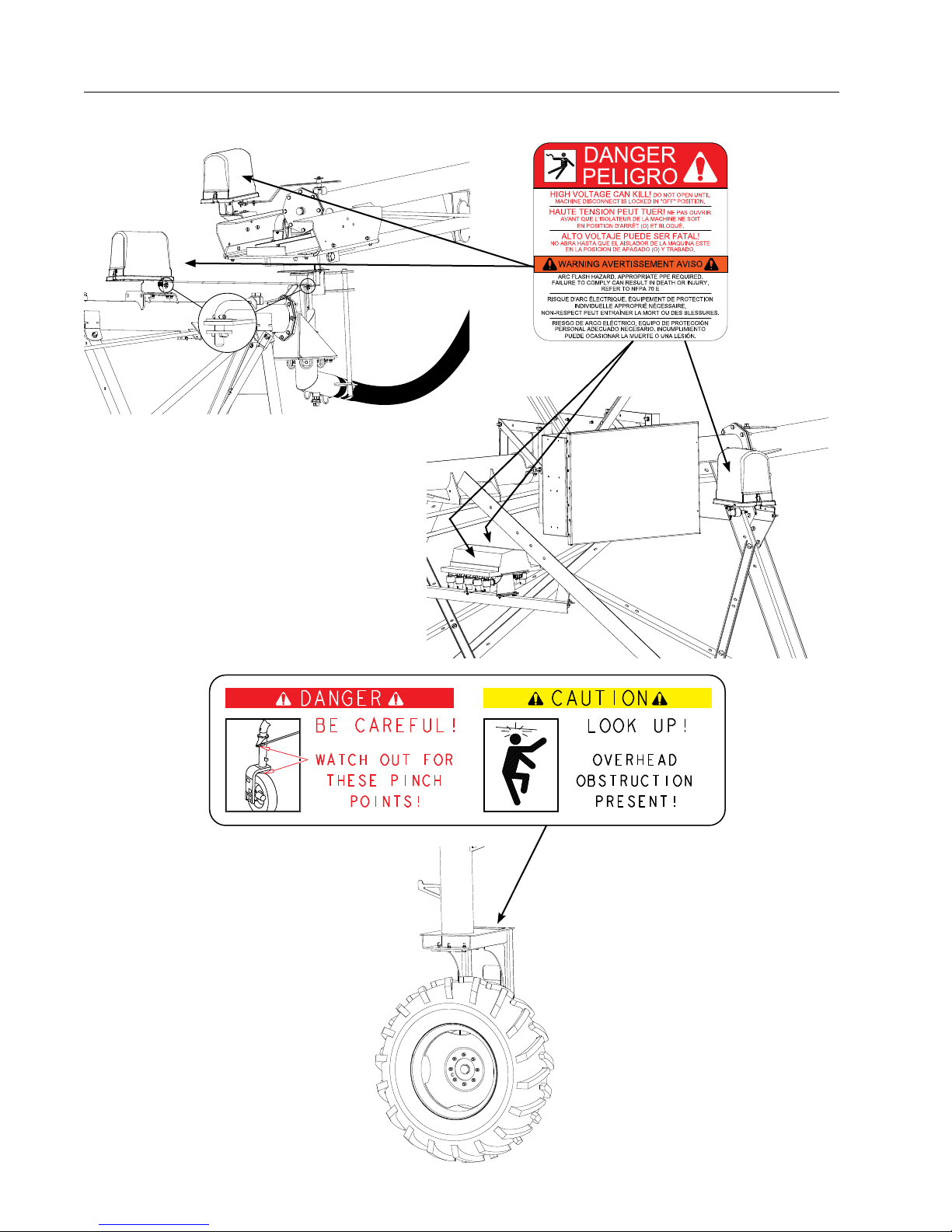
Safety Decals
These Danger, Warning, and Caution decals appear in various locations on a Valley irrigation machine. You
MUST familiarize yourself and other operator’s with these safety decals. For replacement of any decal, contact
your local Valley dealer.
PIPE MOVES WITHOUT WARNING
DO NOT
LIMBS MAY BECOME ENTANGLED, RESULTING IN SEVERE INJURY.
KEEP AWAY FROM DRIVE UNIT DURING OPERATION.
DO NOT
IN THE OFF POSITION.
KEEP TRAY CLEAR OF TOOLS, PARTS OR DEBRIS.
GREASE LARGE & GUIDE ROLLERS REGULARLY.
14
TOUCH MOVING CRADLE OR PIPE, CLOTHING FINGERS OR
SERVICE UNTIL MACHINE IS LOCKED
CAUTION
Page 15
WARNING
Improper installation of this motor may
result in fire, explosion, electrical shock or
other personal injuries. Read operating
instructions
Disconnect power before maintenance.
Open all circuits before removing conduit
box cover. Be sure motor is properly
grounded per local and national codes.
Do not place fingers or objects near
openings.
Do not use eye bolts or lifting hooks to
lift anything except the product.
Safety
Safety Decals (Continued)
15
Page 16
Safety
Safety Decals (Continued)
16
Page 17
Overview
This section briefly describes of the VFlex Corner Sequencing (VCS) Control Panel components and controls.
VCS Control Panel
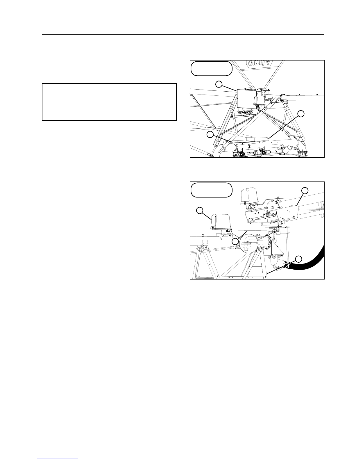
The VCS control panel is mounted on the Steerable
Drive Unit (SDU) above the swing tower box with
platform for access to panel. See Figure 17-1.
VFlex Corner
Application
1
NOTE
• The VCS uses a different sprinkler sequencing box and a non-adjustable sequencing
rod. See Figure 17-2.
2
Term Definitions:
Below are terms that are used throughout the
instruction.
VCS: VFlex Corner Sequencing Control Panel
Corner: The swing arm portion of an irrigation
machine
EEPROM: Electronically Erasable Programmable
Read Only Memory
FLASH: Reprogrammable read only memory
SDU: Steerable Drive Unit
LRDU: Last Regular Drive Unit
Pivot Point: The center of an irrigation system
STB: Smart Tower Board
3
Figure 17-1 1 . VCS Control Panel
2. Swing Tower Box
3. Platform
VFlex Corner
Application
1
2
Figure 17-2 1 . Angle Sensor Box
2. Non-Adjustable Sequencing Rod
3. LRDU
4. Track & Roller
4
3
17
Page 18
Overview
Corner Identification
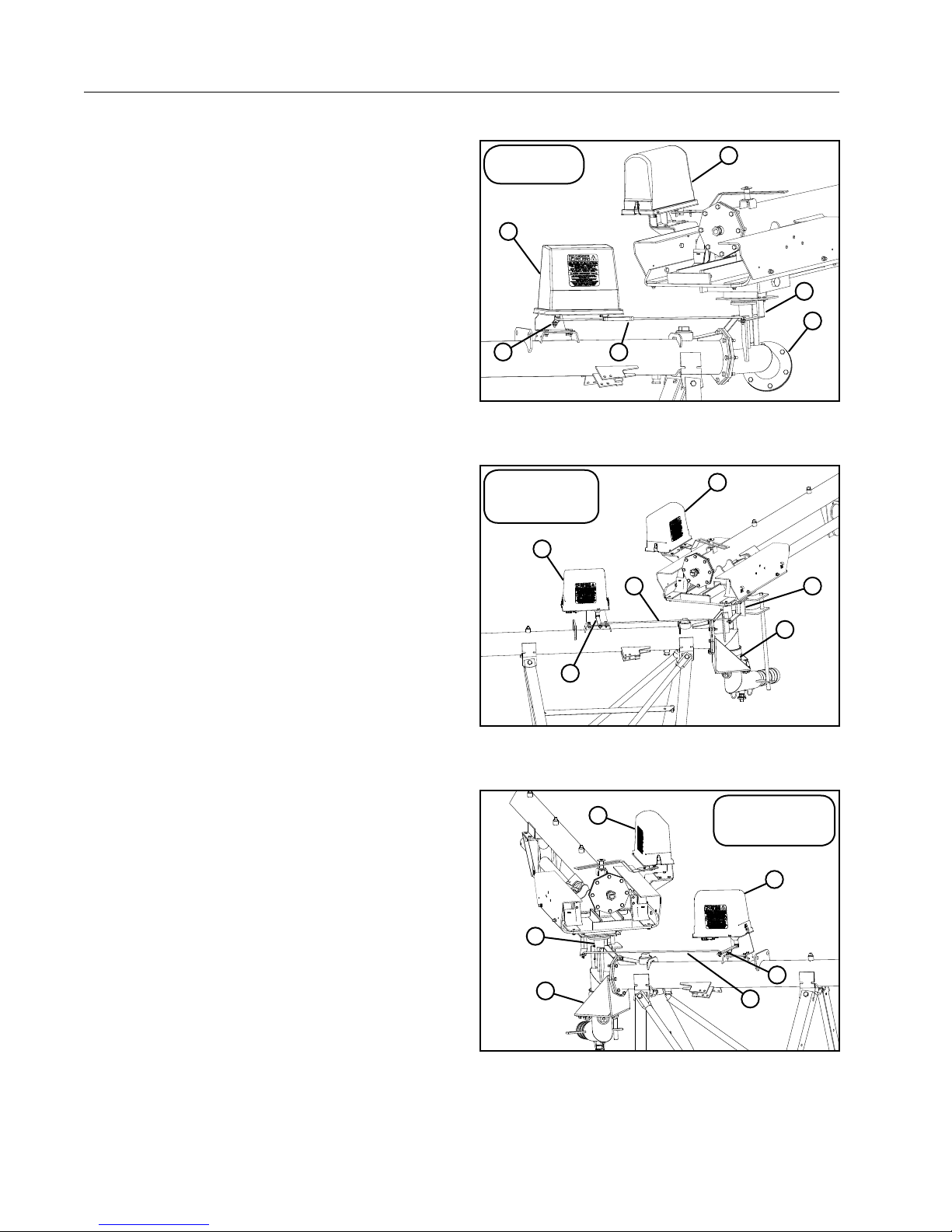
This section briefly describes the possible VFlex
Corner Sequencing component configurations for
standard (trailing) and inverted (leading) corners.
Standard (Trailing) Corner
Orientation for all figures is based on standing
at the pivot point looking towards the LRDU or
standing at the cradle looking towards the SDU.
The Standard (Trailing) corner can use either the fixed
or swivel inlet and either the mechanical sequencing
box or the angle sensor box. See Figures 18-1 and
18-2.
Inlet Option: Both the fixed inlet and swivel inlet
can be used with the standard (trailing) corner. See
Figures 18-1 and 18-2.
Sprinkler Rod T-Bar Mount: Mounted on the right
side of the cradle when standing at the LRDU looking
towards the SDU. See Figures 18-1 and 18-2.
Mechanical Sequencing Box: Used only with a
standard (trailing) corner. Sequencing box control
arm will be on the right side of the pipe at the
LRDU. An adjustable control rod is used with the
mechanical sequencing box. See Figure 18-1.
Angle Sensor Box: Box is mounted with the control
rod on the right side of the pipe at the LRDU. An
fixed control rod is used with the Angle Sensor
Box. See Figure 18-2.
Run Cycle Box: Mounted on the left side of the
cradle. See Figure 18-2.
Mechanical
Sequencing
3
5
Figure 18-1 1 . Fixed Inlet
2. Sprinkler Rod T-bar Mount
3. Mechanical Sequencing Box
Electronic
Sequencing
Standard (Trailing)
3
5
4
6
2
1
4. Adjustable Seq Rod
5. Control Rod Mount
6. Run Cycle Box
6
4
2
1
Inverted (Leading) Corner
Orientation for all figures is based on standing
at the pivot point looking towards the LRDU or
standing at the cradle looking towards the SDU.
The Inverted (Leading) corner can use ONLY the
swivel inlet and the angle sensor box.
Inlet Option: The swivel inlet option can only be used
with the inverted (leading) corner. See Figure 18-3.
Sprinkler Rod T-Bar Mount: Mounted on the left
side of the t-bar. See Figure 18-3.
Angle Sensor Box: Mounted with control arm on the
left side of the pipe. The fixed control rod must be
used with the Angle Sensor Box. See Figure 18-3.
Run Cycle Box: Mounted on the right side of the
cradle. See Figure 18-3.
Figure 18-2 1 . Swivel Inlet
2. Sprinkler Rod T-bar Mount
3. Angle Sensor Box
6
2
1
Figure 18-3 1 . Swivel Inlet
2. Sprinkler Rod T-bar Mount
3. Angle Sensor Box
4. Fixed Seq Rod
5. Control Rod Mount
6. Run Cycle Box
Electronic
Sequencing
Inverted (Leading)
3
5
4
4. Fixed Seq Rod
5. Control Rod Mount
6. Run Cycle Box
18
Page 19
Overview
Main Status Menu
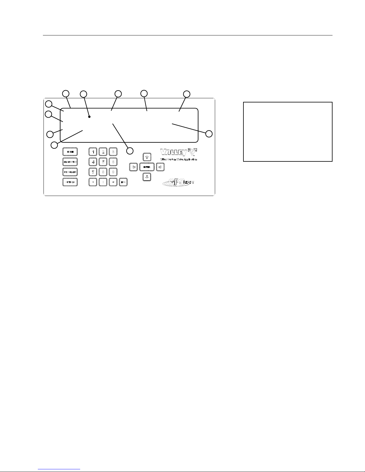
The VCS control panel display is used to show current status and information for programming and selecting
functions. When the control panel main disconnect is turned on and at all other times when the operator is not
programming the control panel, the control panel display shows the current machine status on the status screen.
See Figure 19-1. A short explanation of the status screen elements is given below and on the following pages.
1
2
3
7
hh:mm:ss CANGLE :165 DEG Exx SPEED : xxx%
mm/dd/yy MANGLE :303 DEG ADJ SPEED : xxx%
SOL# TEN+ P :XXX PSI DIR : XXX EG : OFF
10
1234567890123456 MODES: CHEM ANGLE
11
Figure 19-1 1 . Control Panel Display
2. Default Status Screen
3. Time
4. Corner Angle
4
5
8
5. Error Code (Exx)
6. Speed:xxx%
7. Date
8. Machine Angle
Time
Displays the current time according to the clock in the
VCS computer.
If the current time is 1:45:00 P.M., it appears on
the screen in the 24-hour format as 13:45:00
(hh:mm:ss). See Figure 19-1.
Corner Angle (CANGLE)
Displays the current corner angle (CANGLE) as
measured by the corner angle sensor, in degrees.
Error Code (Exx)
This field displays any currently active error codes.
The error code field (Exx) appears only when a
system error has occurred. If multiple errors occur
the error codes will cycle on the display once every
two seconds. Error codes E03-E13 will not appear.
See Figure 19-1.
Active error codes can be acknowledged and cleared
from the status screen by viewing them in the
Diagnostics Screen.
Speed
Displays the current measured percent timer setting
(SPEED:xxx%) from the smart tower board in the
VCS control panel. See Figure 19-1.
6
NOTE
• This Status Screen example
9
9. ADJ Speed:xxx%
10. SOL#
11. TEN+
Date
Displays the current date according to the clock in
the VCS computer.
If the current date is August 18, 2013, it appears
on the screen as 08/18/13 (mm/dd/yy). See Figure
19-1.
Machine Angle (MANGLE)
Displays the current machine angle calculated from
the GPS position. If the machine angle is not valid,
"---" will be displayed. If GPS is not enabled, " " will
be displayed. See Figure 19-1.
Adjusted Speed
Displays the adjusted speed being sent to the Last
Regular Drive Unit (LRDU) when the pressure or
chemigate mode are selected.
SOL#
Displays active solenoids 1-9 on row 4.
TEN+
Displays active solenoids 10-16 on row 4.
illustrates the operating
conditions of a typical irrigation machine. The Status
screen of your machine will
show different conditions.
19
Page 20
Overview
Main Status Menu (Continued)
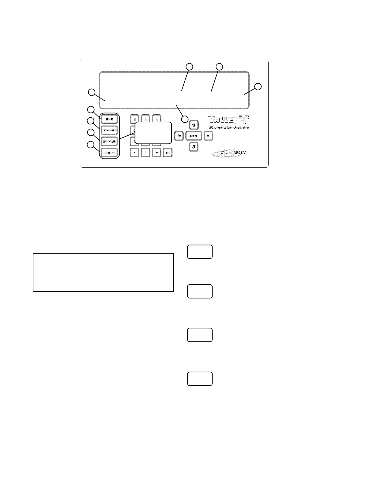
1
hh:mm:ss CANGLE :165 DEG Exx SPEED : xxx%
mm/dd/yy MANGLE :303 DEG ADJ SPEED : xxx%
4
SOL# TEN+ P : XXX PSI DIR : XXX EG : OFF
1234567890123456 MODES: CHEM ANGLE
6
7
8
9
Figure 20-1 1 . Pressure
2. Direction of Machine
3. End Gun Control
FUNCTION
KEYS
Pressure
Displays the current water pressure (P : XXX PSI) as
measured by the pressure transducer connected to
the VCS Control Panel.
Direction
Displays the direction of machine travel (DIR:XXX)
either Forward: FWD, Reverse: REV or Stopped: STP.
5
4. ON Solenoids Displayed
5. Mode Selection
6. Home Key
Function Keys
The function keys are located on the far left side of
the keypad. See Figure 20-1.
The function keys are used to program the panel,
view data and select options not frequently used.
Following are explanations of each function key.
HOME
NOTE
• When used on and Inverted Corner the direction of the machine travel will be the opposite
of the direction displayed on the screen.
End Gun (EG)
Displays the current end gun function: ON or OFF.
Solenoid Numbers
Displays the number of each solenoid (SOL#
TEN+1234567890123456) when it is on. Numbers
are not displayed when solenoids are off.
For example: when solenoids 1, 2, 3, 11 and 12 are
on the display would look as below.
123 12
Modes
Displays the current sprinkler mode and active
override/sprinkler tables.
The sprinkler modes will be displayed as follows:
Chemigate: CHEM
Irrigate: IRR
The override/sprinkler tables will be displayed as follows with the top being the highest priority:
Location: LOC
Angle: ANGLE
Area: AREA
DIAGNOSTICS
PROGRAM
OPTIONS
2
3
7. Diagnostics Key
8. Program Key
9. Options Key
Home Key
Press this key to return to the Status
screen from the screen you are currently
on. See Figure 20-1.
Diagnostics Key
Press this key to determine the cause
of an unplanned machine shutdown or
potential problem situation. See Figure
20-1. Refer to page 29.
Program Key
Press this key to choose the program
for irrigation, chemigation, set sequence
overrides and retracted psi. See Figure
20-1. Refer to page 24.
Options Key
This key is used by your Valley dealer to
configure the VCS control panel during
installation. See Figure 20-1.
20
Page 21
Overview
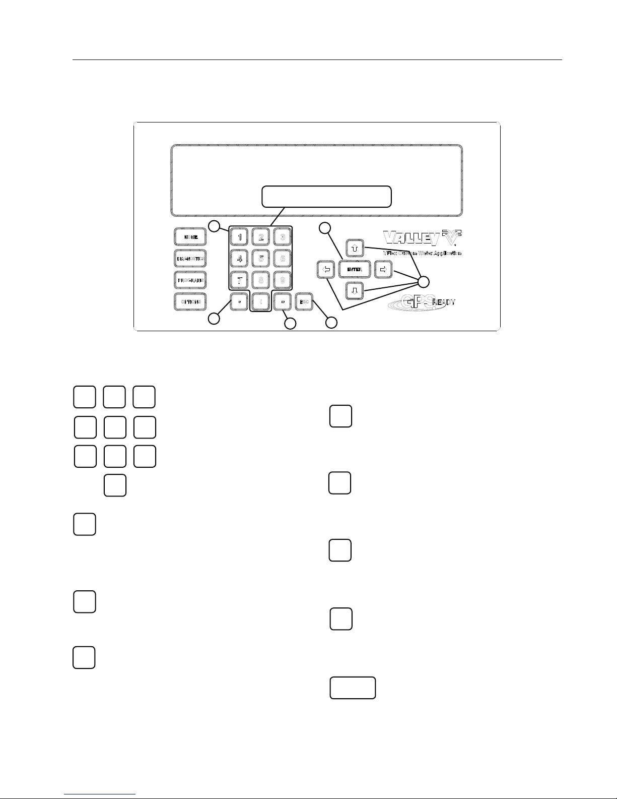
Numeric Entry Keys
The numeric entry keypad is used to input values, such as percentage timer setting, water application depth,
SIS setting, etc. and is also used for programming the panel. The functions of these keys are explained below:
NUMERIC ENTRY KEYS
1
2
Figure 21-1 1 . Number Keys
Number Keys
31 2
Use these keys to select menu
options and enter values. See
654
Figure 21-1.
9
87
2. Decimal Point Key
3. Minus Sign Key.
0
Decimal Point Key
.
Use to input numerical values in decimal
form. See Figure 21-1.
Example: 1.75 inches (44.45 mm).
6
5
3
4
4. Escape Key
5. Navigation Arrow Keys
6. Enter Key
Navigation Arrow Keys
Up Arrow Key
Press this key to increase contrast or make
the characters darker. See Figure 21-1.
Left Arrow Key
Press this key to navigate the menu screen.
See Figure 21-1.
Right Arrow Key
Press this key to navigate the menu screen.
See Figure 21-1.
Minus Sign Key
-
Use to input negative values (generally not
used). See Figure 21-1.
Escape Key
ESC
Use to step backward from the current screen
to a previous screen without performing any
changes. See Figure 21-1.
Repeatedly pressing the Escape key will step
backward from the current screen, through
previous screens until the Status screen is
displayed.
Down Arrow Key
Press this key to decrease contrast or make
the characters lighter. See Figure 21-1.
ENTER
Enter Key
Use at the end of a numerical value entry
or programming sequence. See Figure
21-1.
21
Page 22
Overview
Symbols and Conventions
This manual uses a few symbols and conventions
which are explained below:
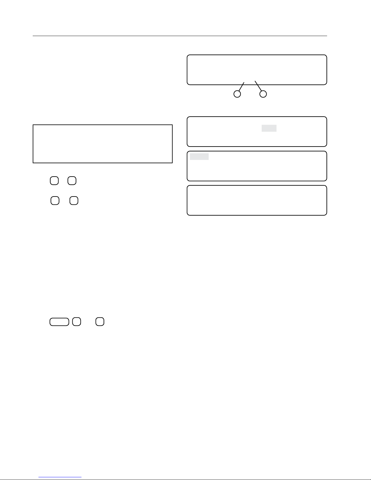
Command Prompt
Any command which requires the operator to input
data will show a command prompt on the bottom line
of the screen.
The command prompt is always identified by > in the
bottom line of the screen. See Figure 22-1.
NOTE
• The value shown in parenthesis indicates
the current value being used by the control
module.
Exiting Screens
Press 0 or
current screen to the previous screen.
Press 0 or
the current screen, through previous screens until
the Status screen is displayed.
ESC
one time to step backward from the
ESC
repeatedly to step backward from
0 EXIT
1 USE CURRENT 30 PSI
2 SET MANUAL
SELECT PRESSURE (30) >
2
Figure 22-1 1 . Command Prompt
2. Default Value
0 EXIT 3 SYSTEM REVIEW LOG
1 SYSTEM FAULTS 4 IO
2 ERROR LOG
PRESS NUMBER >
1 A/D
2 MODULES
3 GPS
PRESS 0 . . EXIT >
0 42 3 1065 6 1234 9 2341
1 709 4 2481 7 0 10 9
2 779 5 2568 8 3698 11 0
PRESS ANY KEY >
Figure 22-2
1
Screen Delays
Any screen that is left for more than five minutes
without pressing a key will revert back to the
previously displayed screen. The Status screen will
eventually be displayed.
Illustrations
The descriptions of procedures throughout this
manual consist of instructions illustrating the key or
series of keys to press followed by the screen that
appears. This convention is used throughout the
manual. Below is an example.
DIAGNOSTICS
Press
See Figure 22-2.
, 4, and 1 to access the A/D screen.
22
Page 23
Starting the VFlex Sequencing Control Panel
Power to the VCS control panel is provided by the
machine control panel.
Operation
Valmont Irrigation
Gen 3 Corner Sequencing
Corner Applications
The VCS control panel is also ON when the following
conditions are met:
• Power is supplied to the pivot.
• The Electronic Sequencing Box disconnect is
ON.
• The machine is in service mode or started or
running.
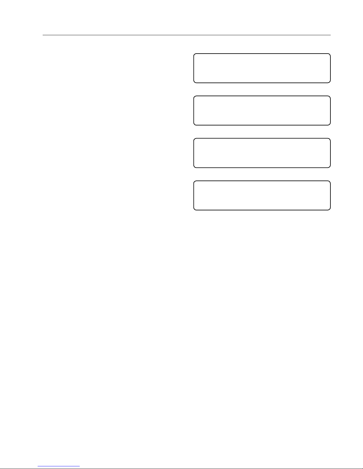
Boot Splash Screen
Figure 23-1 shows the splash screen that appears
while the GPS Guidance System is booting up. (GPS
is optional.)
• mm/dd/yy – the month, day, and year of the
software release
• Ver x.xx – the software version number
VCS Computer Boot Up Screen
Figure 23-2 shows the screen that appears while the
system waits for the VCS computer to boot up.
The remaining wait time is displayed in
minutes:seconds format. The VCS computer will stay
on this screen until communication with the Smart
Tower Board (STB) is established.
mm/dd/yy ver x.yy
Figure 23-1 Splash Screen
SMART TOWER BOARD START UP
(THIS MAY TAKE UP TO 1 MINUTE)
m:ss
Figure 23-2 Startup Screen
ESTABLISHING GPS COMMUNICATIONS
(THIS MAY TAKE UP TO 20 MINUTES)
mm:ss
Figure 23-3
ACQUIRING GPS SIGNAL
CURRENT FIX = NONE
SATS IN VIEW = xx
mm:ss (THIS MAY TAKE UP TO 20 MINUTES)
Figure 23-4
Acquiring Satellites Screen
Figure 23-3 shows the screen that appears while the
system waits for the GPS Receiver to acquire signals
from the satellites if equipped.
The mm:ss field displays how much time
(minutes:seconds) has passed while waiting for
sufficient signal information from the GPS Receiver.
If the time expires and the VCS Computer has yet
to receive sufficient signal information from the GPS
Receiver, the system will open the safety for ten
seconds.
The system displays the message shown in Figure
23-4 until the GPS Receiver finishes acquiring the
signals from the satellites.
23
Page 24
Operation
Programs Key
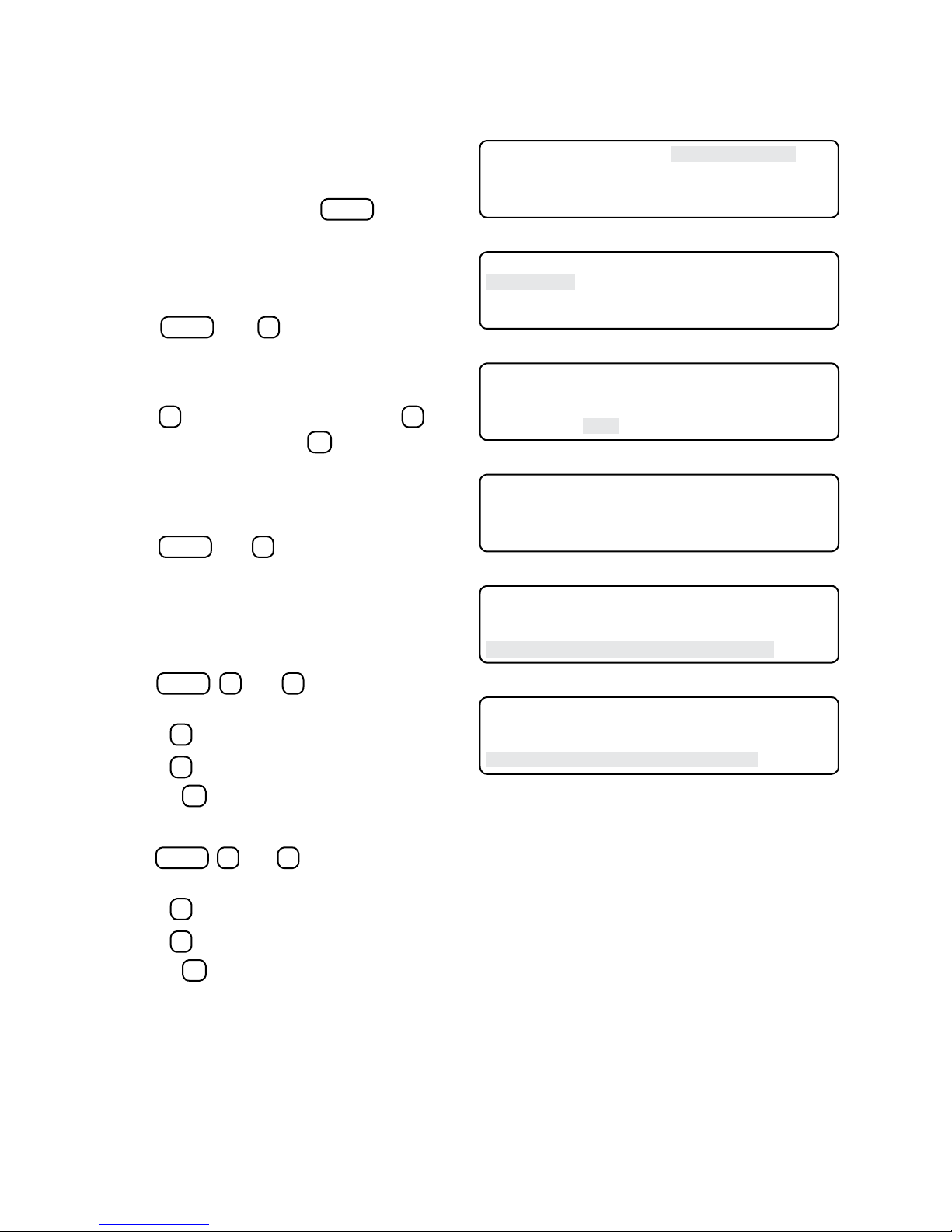
Press this key to choose the programs for irrigation,
chemigation, set sequence overrides, and retracted
psi. To view the program menu, do the following:
1. From the home screen, press
programs main menu. While in this screen if the
pressures regulators are selected it will be displayed like Figure 24-1.
Irr/Chem
2. Press
screen. This screen allows selection of irrigate or
chemigate mode. Irrigate mode is the DEFAULT
setting. See Figure 24-2.
3. Press 1 to select IRRIGATE or press 2 to
select CHEMIGATE. Press
nostics screen. See Figure 24-3.
PROGRAMS
and 1 to display IRR/CHEM
Seq Overrides
To view the Seq Overrides screen, do the following:
4. Press
PROGRAMS
and 2 to display SEQ OVERRIDES screen. This screen allows changes to
be made in the following options screens: Corner
Angle, Position, Corner Angles, and Machine
Angles. See Figure 24-4.
Crnr Angle
5. Press
ANGLE option. See Figure 24-5.
• Press
• Press 0 to Disable.
6. Press the
PROGRAMS
1
to Enable.
ESC
, 2, and 1 to select the CRNR
to return to the previous screen.
PROGRAMS
ESC
to display
to exit to diag-
0 EXIT 3 RETRACTED PSI
1 IRR/CHEM
2 SEQ OVERRIDES
PRESS NUMBER >
Figure 24-1
0 EXIT 3 RETRACTED PSI
1 IRR/CHEM
2 SEQ OVERRIDES
PRESS NUMBER >
Figure 24-2
0 EXIT
1 IRRIGATE
2 CHEMIGATE
SELECT MODE (IRR) >
Figure 24-3
0 EXIT
1 CRNR ANGLE DISABLED 3 CORNER ANGLES
2 POSITION ENABLED 4 MACHINE ANGLES
PRESS NUMBER >
Figure 24-4
0 EXIT
1 CRNR ANGLE DISABLED 3 CORNER ANGLES
2 POSITION ENABLED 4 MACHINE ANGLES
ANGLE MODE 1. . ENABLE 0 . . DISABLE (1) >
Figure 24-5
0 EXIT
1 CRNR ANGLE DISABLED 3 CORNER ANGLES
2 POSITION ENABLED 4 MACHINE ANGLES
POS MODE 1. . ENABLE 0 . . DISABLE (1) >
Figure 24-6
Position
7. Press
8. Press the
24
PROGRAMS
, 2, and 2 to select the Position
option. See Figure 24-6.
1
• Press
to Enable position overrides.
• Press 0 to Disable position overrides.
ESC
to return to the previous screen.
Page 25
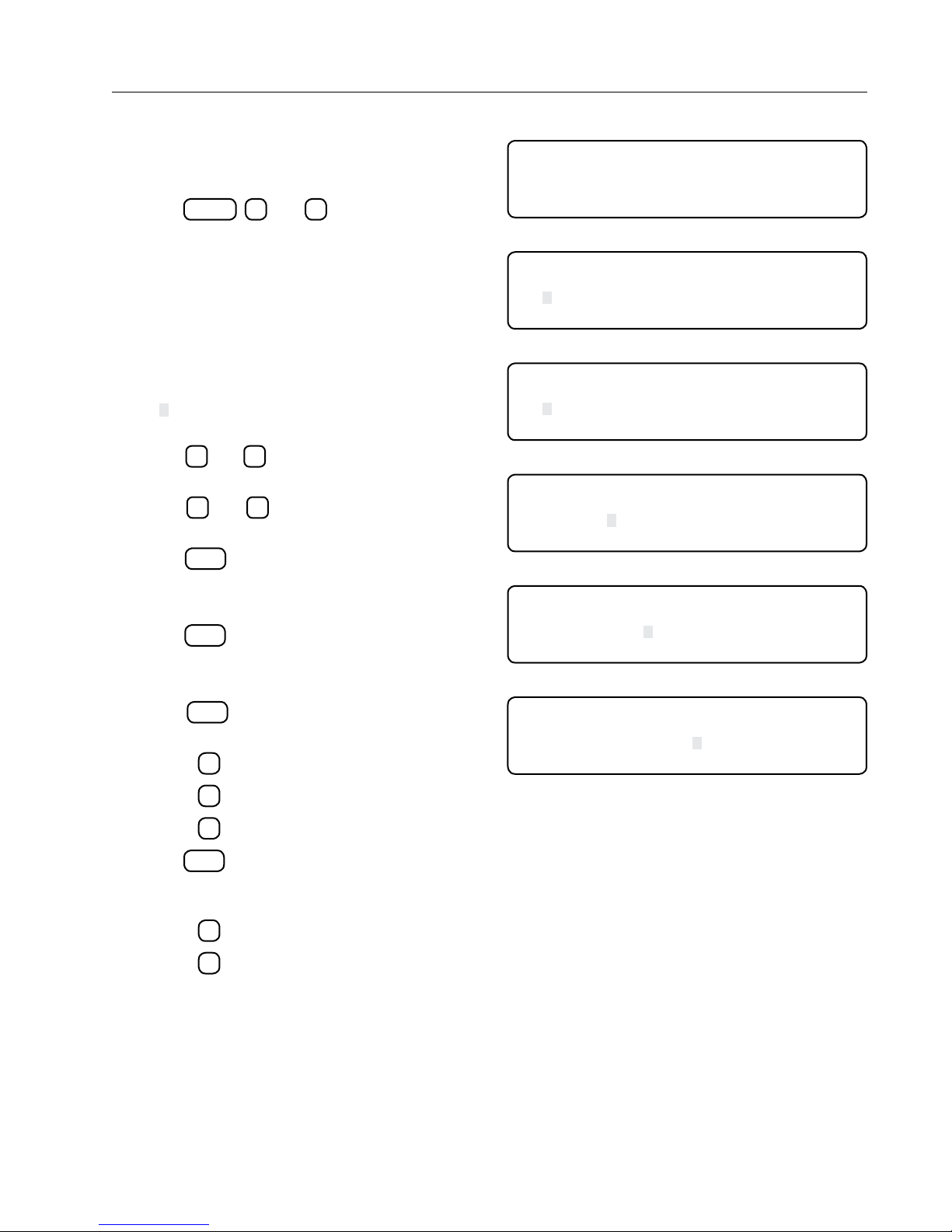
This table allows the user to make changes that
control each solenoid valve allowing different
functions during different corner angles.
9. Press
PROGRAMS
, 2, and 3 to display the Corner
Angles table.
• (Retrying) will only be displayed as shown in
Figure 25-1 if reading the table failed and is
being retried.
10. After the table has been read from the STB Figure 25-2 will be displayed.
• The entry closest to the current corner angle
will be the selected entry.
• " " is the cursor position it will blink allowing
the user to see the data being covered.
• The
and arrow keys will move the cur-
sor to the next or previous field.
arrow keys will scroll the list
• The
and
up or down.
11. Press
ENTER
with cursor located in the CSTART
column to enter start angle. See Figure 25-3.
• Enter start angle: input 60 to 180
ENTER
12. Press
with cursor located in the END col-
umn to enter end angle. See Figure 25-4.
• Enter end angle: input 60 to 180
13. Press
ENTER
with cursor located in the STATE
column to enter corner state. See Figure 25-5.
• Press 1 to select Extension. (EXT)
• Press 2 to select Retraction. (RET)
• Press
14. Press
3
to select No Change. (NOC)
ENTER
to select the 1/0 column. 1/0 is used
to override sequences in the list on (1) or off (0).
See Figure 25-6.
Operation
Corner Angles
READING TABLE FROM SMART TOWER BOARD
(RETRYING)
100%
Figure 25-1
CSTART END S TAT E 1/0 SOL# TEN+
136.5 138.2 EXT 1 123456 1
140. 145.2 EXT 1 1234567 12
139.7 135.0 EXT 0 34 3
Figure 25-2
CSTART END S TAT E 1/0 SOL# TEN+
136.5 138.2 EXT 1 123456 1
140. 145.2 EXT 1 1234567 12
ENTER START ANGLE >
Figure 25-3
CSTART END S TAT E 1/0 SOL# TEN+
136.5 138.2 EXT 1 123456 1
140.0 145.2 EXT 1 1234567 12
ENTER END ANGLE >
Figure 25-4
CSTART END S TAT E 1/0 SOL# TEN+
136.5 138.2 EXT 1 123456 1
140.0 145.2 EXT 1 1234567 12
PRESS 1 . . EXT 2 . . RET 3 . . NOC >
Figure 25-5
CSTART END S TAT E 1/0 SOL# TEN+
136.5 138.2 EXT 1 123456 1
140.0 145.2 EXT 1 1234567 12
PRESS 1 . . ON 2 . . OFF >
Figure 25-6
• Press 1 to turn ON.
• Press
2
to turn OFF.
25
Page 26
Operation
Corner Angles (continued)
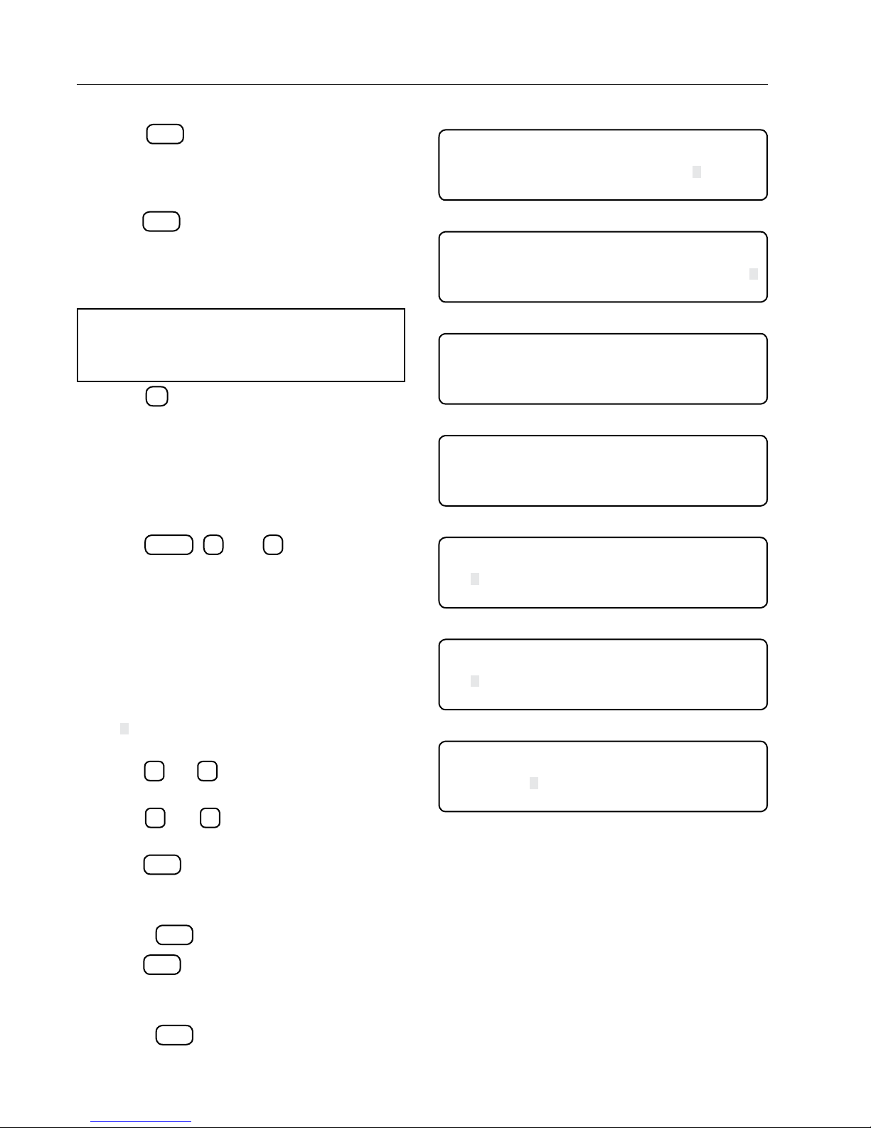
15. Press
column to toggle solenoids. See Figure 26-1.
• Press number to toggle Solenoids that are ON
16. Press
umn to toggle solenoids. See Figure 26-2.
• Press number to toggle Solenoids displayed
ENTER
with cursor located in the SOL#
(1-9). Solonoids shown are ON.
ENTER
with cursor located in the TEN+ col-
(10-16). Solenoids shown are ON.
NOTE
• When solenoid numbers are not displayed
they will be OFF.
17. Press
have occurred the new table will be saved to the
STB. See Figure 26-3.
Machine Angles
This table allows the user to make changes that
control each solenoid valve allowing different
functions during different machine angles.
18. Press
chine Angles table.
• (Retrying) will only be displayed as shown in
19. After the table has been read from the STB Figure 26-5 will be displayed.
• The entry closest to the current corner angle
• " " is the cursor position it will blink allowing
• The
• The
20. Press
column to enter start angle. See Figure 26-6.
• Enter start angle: input 0 to 360.
• Press
21. Press
umn to enter end angle. See Figure 26-7.
• Enter end angle: input 0 to 360.
• Press
ESC
to leave this menu, if any changes
PROGRAMS
, 2, and 4 to display the Ma-
Figure 26-4 if reading the table failed and is
being retried.
will be the selected entry.
the user to see the data being covered.
and arrow keys will move the cur-
sor to the next or previous field.
and
arrow keys will scroll the list
up or down.
ENTER
with cursor located in the MSTART
ENTER
to confirm angle.
ENTER
with cursor located in the END col-
ENTER
to confirm angle.
CSTART END S TAT E 1/0 SOL# TEN+
136.5 138.2 EXT 1 123456 1
140.0 145.2 EXT 1 1234567 12
PRESS NUMBER TO TOGGLE >
Figure 26-1
CSTART END S TAT E 1/0 SOL# TEN+
136.5 138.2 EXT 1 123456 1
140.0 145.2 EXT 1 1234567 12
PRESS NUMBER TO TOGGLE >
Figure 26-2
WRITING TABLE TO SMART TOWER BOARD
(RETRYING)
100%
Figure 26-3
READING TABLE FROM SMART TOWER BOARD
(RETRYING)
100%
Figure 26-4
MSTART END 1/0 SOL# TEN+
136.5 138.2 1 123456 1
140. 145.2 1 1234567 12
0.0 0.0 0 34 3
Figure 26-5
MSTART END 1/0 SOL# TEN+
136.5 138.2 1 123456 1
140. 145.2 1 1234567 12
PRESS START ANGLE >
Figure 26-6
MSTART END 1/0 SOL# TEN+
136.5 138.2 1 123456 1
140. 145.2 1 1234567 12
PRESS END ANGLE >
Figure 26-7
26
Page 27
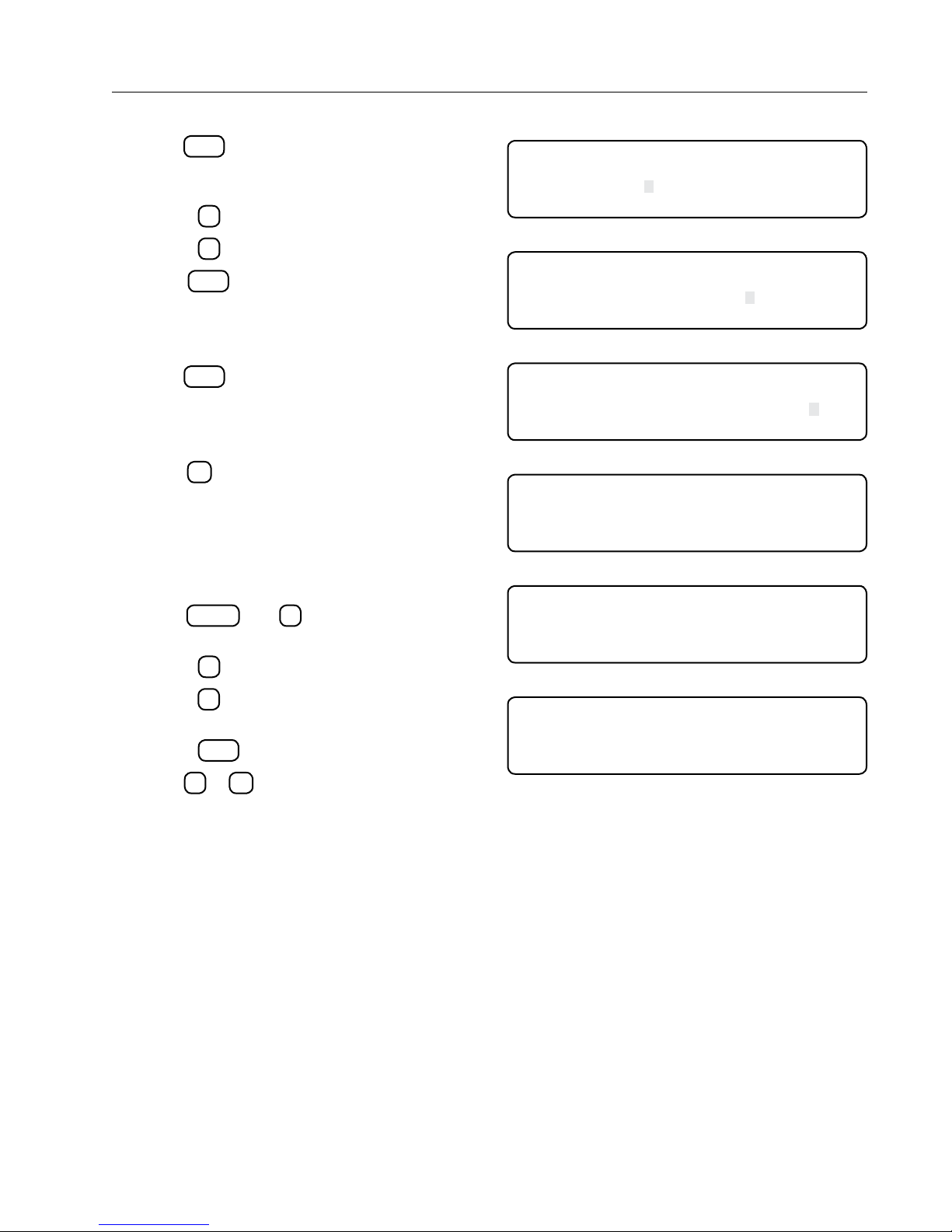
22. Press
ENTER
to select the 1/0 column. 1/0 is used
to override sequences in the list on (1) or off (0).
See Figure 27-1.
• Press 1 to turn ON.
• Press 2 to turn OFF.
23. Press
ENTER
with cursor located in the SOL#
column to toggle solenoids. See Figure 27-2.
• Press number to toggle Solenoids that are ON
(1-9). Solonoids shown are ON.
24. Press
ENTER
with cursor located in the TEN+ column to toggle solenoids. See Figure 27-3.
• Press number to toggle Solenoids displayed
(10-16). Solenoids shown are ON.
25. Press
ESC
to leave this menu, if any changes
have occurred the new table will be saved to the
STB. See Figure 27-4.
Operation
Machine Angles (continued)
MSTART END 1/0 SOL# TEN+
136.5 138.2 1 123456 1
140. 145.2 1 1234567 12
PRESS 1 . . ON 2 . . OFF >
Figure 27-1
MSTART END 1/0 SOL# TEN+
136.5 138.2 1 123456 1
140. 145.2 1 1234567 12
PRESS NUMBER TO TOGGLE >
Figure 27-2
MSTART END 1/0 SOL# TEN+
136.5 138.2 1 123456 1
140. 145.2 1 1234567 12
PRESS NUMBER TO TOGGLE >
Figure 27-3
WRITING TABLE TO SMART TOWER BOARD
(RETRYING)
100%
Retracted Psi
This menu is only functional when pressure regulators
are not selected. See Figure 27-5.
26. Press
psi screen. See Figure 27-6.
• Press 1 to use current psi setting.
• Press 2 to set psi setting manually. Min. 5 psi
• Press
27. Press 0 or
PROGRAMS
and 3 to display the retracted
to Max. 150 psi.
ENTER
to confirm entered data.
ESC
to leave this menu.
Figure 27-4
0 EXIT
1 USE CURRENT 30 PSI
2 SET MANUAL
PRESS NUMBER >
Figure 27-5
0 EXIT
1 USE CURRENT 30 PSI
2 SET MANUAL
SELECT PRESSURE (30) >
Figure 27-6
27
Page 28

Operation
28
Page 29
Diagnostics
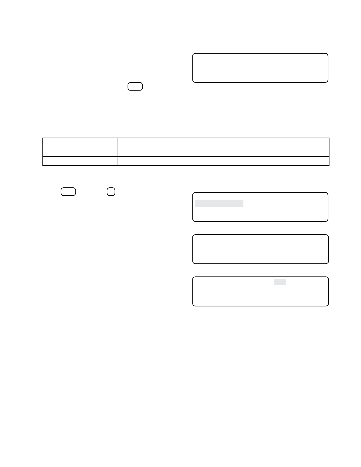
Diagnostics Screen
The Diagnostics section provides an overview of
using the diagnostic features incorporated into the
VCS Control Panel. Diagnostics aid in identifying VCS
failures, troubleshooting, and correcting problems.
Press the Diagnostics button
DIAGNOSTICS
to view the
Diagnostics Screen. See Figure 29-1.
System Faults
System Faults are failures that shut the machine down. Any item showing FAULT on the System Fault screen is
the reason why the machine had shut down. See the Troubleshooting section for possible causes and corrective
action. See Figure 29-2.
FAULT – STB FLASH Smart Tower Board flash checksum failed
FAULT – STB EEPROM STB EEPROM checksum failed
FAULT – STB SOFTWARE STB and VCS software versions are not compatible
Figure 29-2
Viewing System Faults
Press
Faults screen. When a recognized fault causes
the machine to shut down, FAULT appears next to
the item responsible for the shut down. FAULT is
automatically cleared the next time the machine runs
successfully. See Figure 29-3.
This screen will be skipped if there is an active fault.
Instead, the submenu with the highest priority active
faults will be displayed like in the examples. See
Figure 29-4.
DIAGNOSTICS
and then 1 to display the System
Status Screen Diagnostics
If a failure occurs, an error code appears on the Main
Display screen. If multiple errors have occurred,
those errors will appear in a sequence every second.
Only error codes 1, 2, 4, 6, 11, 12, 15, 16, 17, 18, 19,
and 20 will appear. See Figure 29-5.
0 EXIT 3 SYSTEM REVIEW LOG
1 SYSTEM FAULTS 4 IO
2 ERROR LOG
PRESS ENTER >
Figure 29-1
0 EXIT 3 SYSTEM REVIEW LOG
1 SYSTEM FAULTS 4 IO
2 ERROR LOG
PRESS ENTER >
Figure 29-3
1 STB FLASH OK
2 STB EEPROM FAU LT
3 STB SW OK
PRESS 0. .EXIT NUMBER..MORE INFO
Figure 29-4
hh:mm:ss CANGLE: 165 DEG E01 SPEED: xxx%
mm/dd/yy MANGLE: 303
SOL# TEN+
123 12 MODES: CHEM ANGLE
Figure 29-5
P: 100
DEG
PSI
ADJ SPEED: xxx%
DIR:FWD EG:OFF
29
Page 30

Diagnostics
Error Code Summary
A list of possible error codes appears below in Figure 30-1. See the Troubleshooting section for possible causes
and corrective actions. Refer to Error Codes on page 36 for corrective actions.
E01 – BATTERY BACKED RAM – CHECKSUM
FAILED AT POWER UP
E02 – EEPROM – CHECKSUM FAILED AT
POWER UP
E03 – UNIT RESETS – THIS IS LOGGED WHEN
THE SOFTWARE RESETS
E04 – KEYPAD – POSSIBLE KEY STUCK,
CHECK KEYPAD CONNECTION
E06 – STB COMMUNICATIONS STB communications error.
E11 – STB FLASH – CHECKSUM FAILED AT
POWER UP
E12 – STB EEPROM – CHECKSUM FAILED AT
POWER UP
E13 – STB UNIT RESETS – THIS IS LOGGED
WHEN THE SOFTWARE RESETS
E15 – STB SOFTWARE ERROR – STB AND VCS
SOFTWARE VERSION ARE NOT COMPATIBLE
E16 – STB SENSOR REFERENCE ERROR The 5 VDC that supplies power to the system sensors in
E17 – STB GPS ERROR – CHECK STB AND
GPS CABLE CONNECTIONS
E18 – STB PRESSURE ERROR – PRESSURE
SENSOR READING IS OUT OF RANGE
A BBRAM memory error has occurred in the Control Panel
Module.
A EEPROM memory error has occurred in the Control
Panel Module.
The machine has reset for some reason.
A key on the keypad is stuck and has been sending a
continuous signal to the machine for at least 10 minutes.
The flash memory in the STB is corrupt.
EEPROM memory in the STB is corrupt.
STB reset unexpectedly, there are a number of possible
causes for this error.
Software that is running on the panel module and the
STB are not compatible.
out of tolerance.
No data coming from the GPS receiver or GPS guidance
system.
The pressure transducer input for the system is outside
normal operating limits.
E19 – STB ANGLE ERROR – PRESSURE
ANGLE SENSOR READING IS OUT OF RANGE
E20 – OVERRIDE TABLE – CHECKSUM FAILED
AT POWER UP
Figure 30-1
Angle sensor input for the system is outside its normal
operating limits.
The storage are that contains the override tables is
corrupt.
30
Page 31
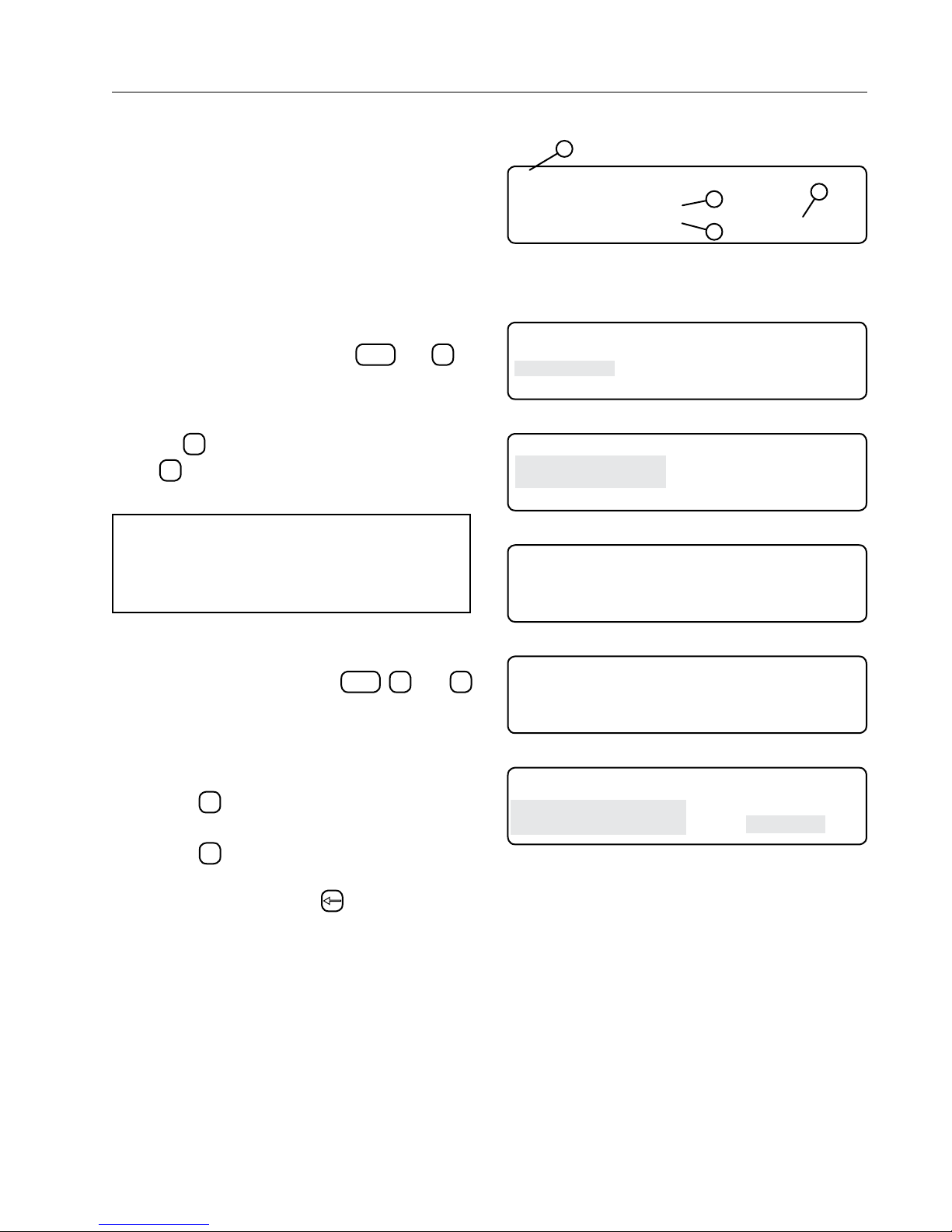
For each error code there is an error log. Each entry
in the log records the following information about the
error:
• the time and date when it first occurred
• the time and date when it last occurred
• the total number of occurrences
See Figure 31-1.
Viewing An Error Log
To view an Error Log, do the following:
DIAGNOSTICS
1. From the Status screen, press
and 2 to
display Error Log screen. See Figure 31-2. This
will allows you to navigate through logged errors.
2. To view a different System Review Log screen,
press 1 to search backward toward screen 99
or 2 to search forward toward screen 01. See
Figure 31-3.
NOTE
• Viewing the Error Log screen clears the error
codes from the Main Display screen until a
new error is recorded.
Diagnostics
Error Logs
1
E01 BATTERY BACKED RAM - CHECKSUM
FAILED AT POWER UP
FIRST :14:26:35 12/28/99
LAST :13:36:07 01/04/00 COUNT= 5
Figure 31-1 1 . Error Code
2. First Occurrence Time and Date
3. Last Occurrence Time and Date
4. Total Occurrences
0 EXIT 3 SYSTEM REVIEW LOG
1 SYSTEM FAULTS 4 IO
2 ERROR LOG
PRESS ENTER >
Figure 31-2
0 EXIT
1 SEARCH BACKWARD
2 SEARCH FORWARD
PRESS ENTER >
Figure 31-3
E01 BATTERY BACKED RAM - CHECKSUM
FAILED AT POWER UP
FIRST :00:00:00 01/01/90
LAST :00:00:00 01/01/90 COUNT= 0
2
3
4
Resetting An Error Log To Zero
To reset an Error Log to zero, do the following:
1. Press the Diagnostics button
to display the E01 Error Log screen. See Figure
31-4.
2. Locate the desired error log screen to reset. See
Figure 31-5.
• Press 1 to search backward through the Er-
ror Logs.
• Press 2 to search forward through the Error
Logs.
3. Press the Back Arrow key
The count is reset to zero and the first and last
occurrences are set to the current time and date. See
Figure 31-6.
DIAGNOSTICS
, 2, and 1
two times.
Figure 31-4
E04 KEYPAD - POSSIBLE KEY STUCK,
CHECK KEYPAD CONNECTION
FIRST :07:23:23 07/08/07
LAST :08:37:18 07/09/07 COUNT= 4
Figure 31-5 Selected Error Log
E04 KEYPAD - POSSIBLE KEY STUCK,
CHECK KEYPAD CONNECTION
FIRST :12:26:35 07/10/07
LAST :12:26:35 07/10/07 COUNT= 0
Figure 31-6
31
Page 32
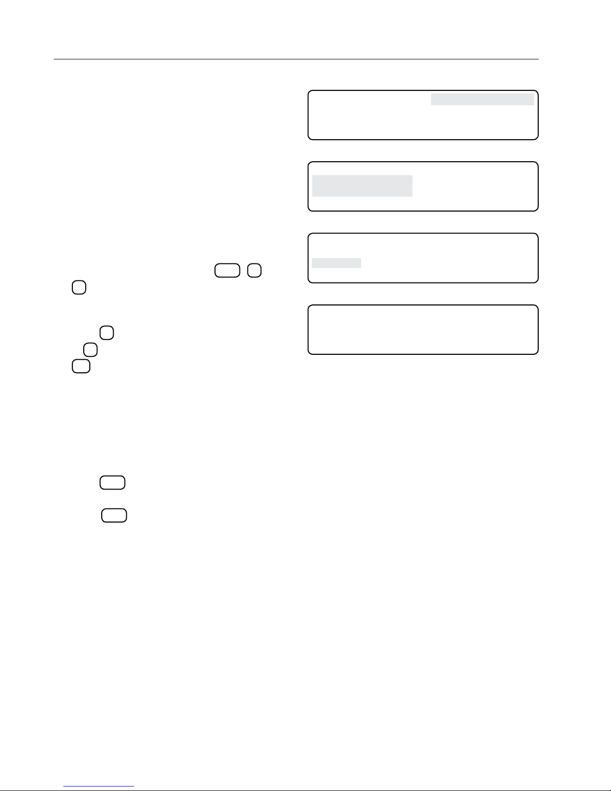
Diagnostics
System Review Log
The System Review Log contains a record of up
to 99 of the most recent machine operation status
changes. Review 01 is the newest status change and
Review 99 is the oldest status change. The review
screen number appears in the lower left-hand corner.
You can analyze a status change further by displaying
a record of all its related error codes. Reading
from left to right, error codes E20 through E01 are
represented by a 0 placeholder. If an error occurred,
the placeholder representing the error code changes
from 0 to 1.
0 EXIT 3 SYSTEM REVIEW LOG
1 SYSTEM FAULTS 4 IO
2 ERROR LOG
PRESS ENTER >
Figure 32-1
0 EXIT
1 SEARCH BACKWARD
2 SEARCH FORWARD
PRESS ENTER >
Figure 32-2
Reviewing Status Changes and
Errors
1. From the Status screen, press
1
to display System Review Log screen 01.
See Figure 32-1.
2. To view a different System Review Log screen,
press 1 to search backward toward screen 99
or 2 to search forward toward screen 01. Press
esc
to exit to diagnostics screen. See Figure
32-2.
Example review screen:
Review.xx is the review screen being viewed, xx =
01 to 99.
Review.01 is the most recently logged review screen.
See Figure 32-3.
3. While in the desired System Review Log screen,
press
OPTIONS
to display the Error Review screen.
See Figure 32-4.
4. Press
OPTIONS
again to return to the System Re-
view Log screen.
Error codes (xxxxxxxxxxxxxxxxxxxx) is the recently
logged error codes logged with the review screen in
binary format where the right most digit is E01.
DIAGNOSTICS
, 3, and
hh:mm:ss CANGLE: 165 DEG E01 SPEED: xxx%
mm/dd/yy MANGLE: 303
REVIEW.01 TEN+ P: 100
123 12 MODES: CHEM ANGLE
Figure 32-3
ERROR CODES: xxxxxxxxxxxxxxxxxxxx
REVIEW. 01
Figure 32-4
DEG
PSI
ADJ SPEED: xxx%
DIR:FWD EG:OFF
32
Page 33
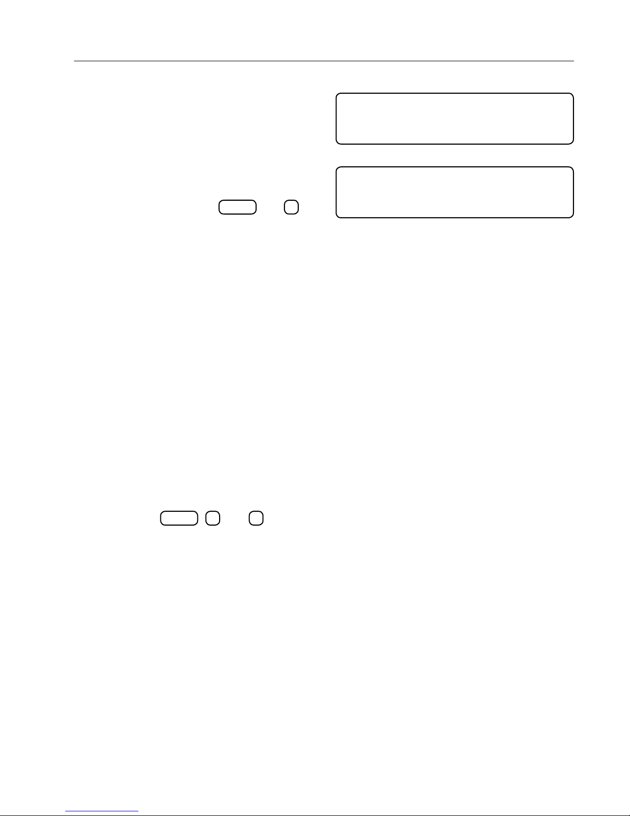
IO is used to review machine information collected
by the control panel. The following data types are
currently available:
• A/D - Review analog voltages for troubleshooting.
• Modules - Review the status of selected relays. A
relay is considered a module.
• GPS - Review a machine's current location and
heading.
From the main screen, press
SYSTEMDIAGNOSTICS
and 4 to
display the IO screen. See Figure 33-1.
A/D - Analog to Digital Voltages
A/D is used to review analog voltages. There are
twelve analog channels (0 through 11) available for
monitoring voltage feedback. Below is a description
of each channel.
• Channel 0 monitors voltage from the pressure
transducer. An acceptable range is between 1000
and 15 mV.
• Channel 1 monitors voltage from the angle sensor. For more information, see the Angle Setup
section beginning on page 25.
• Channels 2 through 7 are not used. Ignore any
random values that might appear.
• Channel 8 monitors voltage from the 5 VDC power
supply. An acceptable range is between 4750 and
5000 mV.
• Channels 9 through 11 are not used. Ignore any
random values that might appear.
Diagnostics
IO
1 A/D
2 MODULES
3 GPS
PRESS 0 . . EXIT
Figure 33-1
0 42 3 0 6 0 9 0
1 709 4 0 7 0 10 0
2 0 5 0 8 3698 11 0
PRESS ANY KEY >
Figure 33-2
Reviewing A/D
To review analog voltages, start from the Status
SYSTEMDIAGNOSTICS
screen and press
the A/D screen. See Figure 33-2.
Press any key to exit this screen.
, 4, and 1 to display
33
Page 34
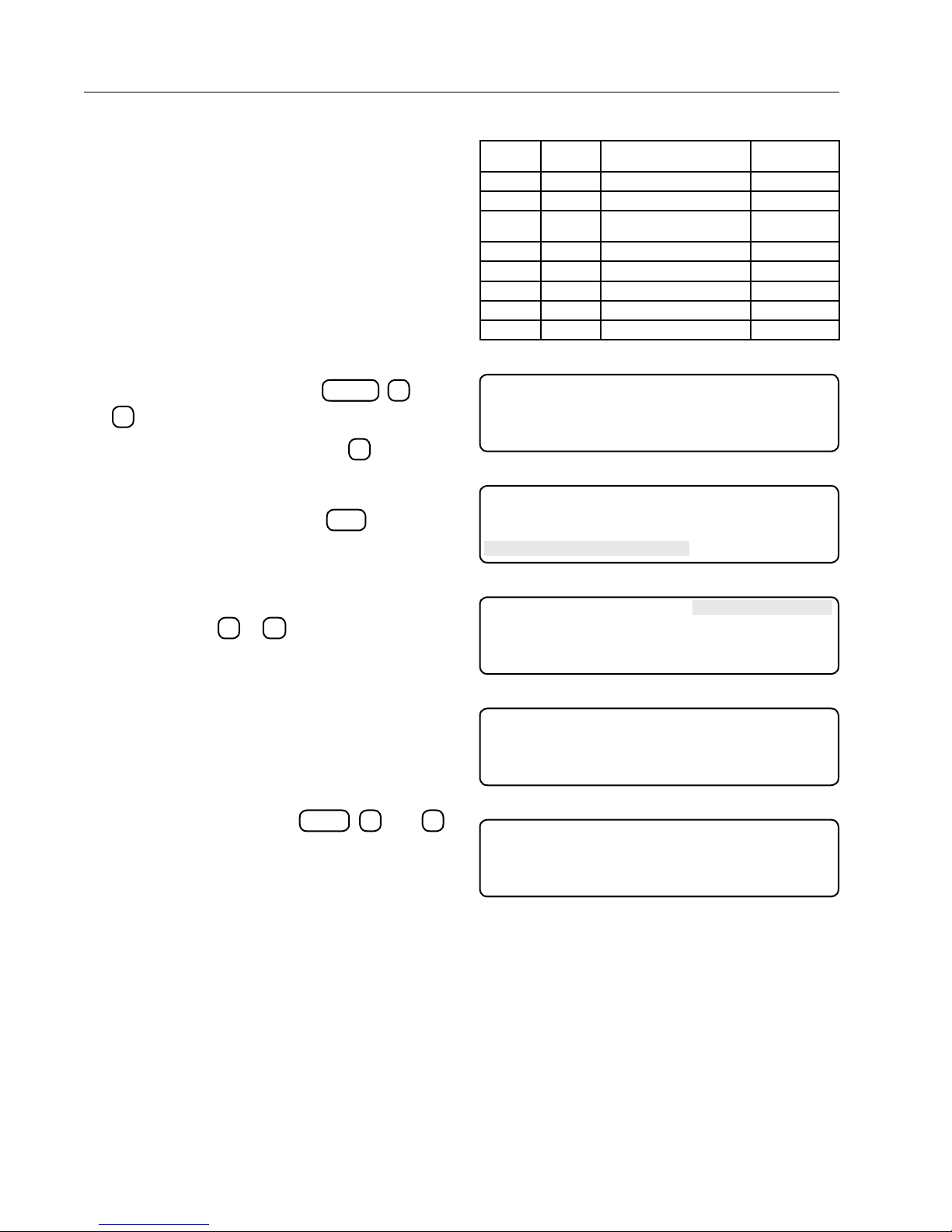
Diagnostics
Modules
Module is another name for a relay. The machine is
monitored and controlled by a series of relays located
in the control panel. Each relay will be closed (ON) or
open (OFF) as the machine is operating.
Enter a module number in the Review Modules
screen and the module number and its status appear
in the upper right-hand corner of the Modules screen.
A list of the module numbers and their corresponding
relays is shown in Figure 34-1.
Reviewing Modules
To review module relays, do the following:
1. From the Status screen, press
2
to display the Modules screen.
2. From the Modules screen, press
the Modules Request screen. See Figure 34-2.
3. From the Modules Request screen, press the
desired module number and
the selected module ("22" in this example) in the
upper right-hand corner. See Figures 34-3 and
34-4.
4. Repeat steps 2 and 3 to display other module
relays or press 0 or
ESC
to exit this screen.
GPS
The Navigation screens inform you of the machine's
current position and how far it has deviated from
its intended path. This read-only information is in
degrees and meters. You can not adjust a machine's
path with these screens.
SYSTEMDIAGNOSTICS
1
to display
ENTER
to display
, 4, and
MODULE
NUMBER
0 K1 Safety Out J5-1
1 K2 LRDU Enable J5-2
5 K9 12 VDC for GGS Computer and
6 K12 Steer In Output J7-1, 2
7 K13 Steer Out Output J7-3, 4
19 K15 Reverse Sense J7-7, 8
20 K14 Steer Enable Input J7-5, 6
23 K5 Safety Input Sense J5-7
Figure 34-1
0 EXIT MODULE 0 OFF
1 MODULE
PRESS NUMBER > 1
Figure 34-2
0 EXIT MODULE 0 OFF
1 MODULE
ENTER MODULE NUMBER > 22
Figure 34-3
0 EXIT MODULE 22 ON
1 MODULE
PRESS NUMBER >
Figure 34-4
GPS FIX TYPE: STANDARD
LAT: - 12.3456789 DEG ALT: -- 234.56 M
LON: - 123.4567890 DEG
PRESS ANY KEY >
RELAY
NUMBER
FUNCTION DESCRIPTION RELAY BOARD
GPS
TERMINAL
J6-1, 2, 3
Reviewing GPS
From the Status screen, press
to display the GPS screen. See Figures 34-5 and
34-6.
Press any key to exit this screen.
34
SYSTEMDIAGNOSTICS
, 2, and 3
Figure 34-5 With GPS Screen
GPS FIX TYPE: - - - - LAT: - - - - - DEG ALT: - - - - - M
LON: - - - - - DEG
PRESS ANY KEY >
Figure 34-6 Without GPS Screen
Page 35
Troubleshooting
WARNING
Use this section with the machine owner's manual to diagnose and troubleshoot problems with the machine
and/or control panel. Keep in mind the following precautions:
• Always perform service or maintenance safely.
• Use personal protection equipment when required.
• Maintain a minimum working clearance around the control panel and other equipment.
• Use fall protection when required.
• Always use at least the minimal lockout/tagout procedure when maintaining or servicing the machine.
!
• TO REDUCE THE POSSIBILITY OF SEVERE INJURY OR DEATH:
• TROUBLESHOOTING OR REPAIRING ELECTRICAL PROBLEMS SHOULD ONLY BE PERFORMED
BY A QUALIFIED VALLEY DEALER.
• ALWAYS CONTACT YOUR LOCAL VALLEY DEALER TO TROUBLESHOOT OR CORRECT ANY ELECTRICAL PROBLEMS ON OR ASSOCIATED WITH THE CONTROL PANEL OR MACHINE. NEVER ATTEMPT TO TROUBLESHOOT OR CORRECT ELECTRICAL PROBLEMS ON YOUR OWN.
• USE PERSONAL PROTECTION EQUIPMENT WHEN REQUIRED.
• MAINTAIN A MINIMUM WORKING DISTANCE AROUND THE CONTROL PANEL AND OTHER EQUIPMENT.
• USE FALL PROTECTION WHEN REQUIRED.
• BEFORE SERVICING OR PERFORMING MAINTENANCE ON THE MACHINE, ALWAYS SHUT OFF
ALL ELECTRICAL POWER TO THE CONTROL PANEL AND MACHINE, THEN USE THE MINIMAL
LOCKOUT/TAGOUT PROCEDURE ON THE SERVICE DISCONNECT AND CONTROL PANEL.
For more information see the Safety section.
35
Page 36
Troubleshooting
System Faults
Figure 36-1 is a table that lists and describes possible system faults, possible cause(s), whether the machine
shuts down when the error occurs, and corrective action(s) to take.
SYSTEM FAULT DESCRIPTION WITH POSSIBLE CAUSES SHUTDOWN CORRECTIVE ACTION
STB FLASH FAULT The memory area containing the currently running software
os corrupt.
Causes:
• Static discharge to the board.
• Damaged flash memory on the board.
STB EEPROM FAULT The memory are containing runtime parameters and
machine configuration is corrupt.
Causes:
• STB powered off while the system was writing information to this are of memory.
• EEPROM on board could be damaged.
Fixes:
• Hard reset may fix this error.
STB SOFTWARE The STB was restarted unexpectedly.
Causes:
• Poor power or power connection to the STB.
• Static discharge to the board.
• Excessive electrical noise in the panel.
Figure 36-1
YES
YES
YES
Contact your Valley dealer.
Contact your Valley dealer.
Contact your Valley dealer.
Error Codes
The following table lists all the possible error codes, with their descriptions, the threshold for the error to occur,
whether the machine shuts down due to the error, and possible causes or corrective actions to take. See Figure
36-2 below and Figure 37-1 on the next page.
ERROR DESCRIPTION THRESHOLD
E01 BATTERY BACKED RAM
– CHECKSUM FAILED AT
POWER UP
E02
E03
E04
Figure 36-2
EEPROM
FAILED AT POWER UP
UNIT RESETS
LOGGED WHEN THE
SOFTWARE RESETS
KEYPAD
STUCK, CHECK KEYPAD
CONNECTION
– CHECKSUM
– THIS IS
– POSSIBLE KEY
One of the
blocks failed.
10 minutes YES Keypad failure or key stuck. A key that is logged
SYSTEM
FAU LT
SHUT
DOWN
YES CheckSum incorrect in BBRAM section of
memory.
Weak batteries in Real-time Clock (BBRAM) can
cause error. The batteries can last up to 10
years. Replace Real-time Clock if this error
occurs.
Contact your Valley Dealer.
YES CheckSum incorrect in EEPROM section of
memory.
Error can occur when power is lost while entering
constants, which can also result in loss of data.
Try to Hard Reset Module.
Contact your Valley Dealer.
NO Records software resets caused by power cycles
or electrical switching noise that disturbs the
computer processor.
as stuck is ignored until the power is cycled on
the Control Panel Module.
Contact your Valley Dealer.
POSSIBLE CAUSES
or
CORRECTIVE ACTION
SHOWN
ON
SCREEN
YES
YES
NO
YES
36
Page 37
Troubleshooting
Error Codes (continued)
ERROR DESCRIPTION THRESHOLD
E06 STB COMMUNICATIONS
ERROR, CHECK STB AND
CABLE CONNECTIONS
E11 STB FLASH – CHECKSUM
FAILS AT POWER UP
E12 STB EEPROM – CHECKSUM
FAILED AT POWER UP
E13 STB UNIT RESETS – THIS IS
LOGGED WITH THE
SOFTWARE RESETS
E15 STB SOFTWARE ERROR –
STB AND VCS SOFTWARE
VERSION ARE NOT
COMPATIBLE
E16 STB SENSOR REFERENCE
ERROR
E17 STB GPS ERROR – CHECK
STB AND GPS CABLE
CONNECTIONS
1 SECOND YES Communications with the relay board is lost. YES
10 seconds NO Power Supply to the system sensors is not within
SYSTEM
FAU LT
SHUT
DOWN
Communications lost with the STB.
Contact Your Valley Dealer.
YES STB flash memory is corrupt. YES
Contact your Valley Dealer.
YES EEPROM memory is corrupt, loss of power while
saving machine configuration parameters or
runtime data.
If error 19 occurred previously, verify proper
wiring and calibration of angle sensor.
Contact your Valley Dealer.
NO STB has rebooted during normal operation.
Caused by low power supply voltage or loose
connection.
Contact your Valley Dealer.
The versions of software running on the STB
and panel module are not compatible.
Board or module was replaced or firmware was
updated in only one part of the system.
Contact your Valley Dealer.
the acceptable range.
Short in sensor cabling.
Sensor malfunction or board malfunction.
NO There is not any location data coming from the
GPS receiver or GPS guidance system.
This could be could be due to an obstructed view
of the sky or a cabling failure.
Contact your Valley dealer.
POSSIBLE CAUSES
or
CORRECTIVE ACTION
SCREEN
SHOWN
ON
YES
NO
YES
YES
YES
E18 STB PRESSURE ERROR –
PRESSURE SENSOR
READING IS OUT OF RANGE
E19 STB ANGLE ERROR –
ANGLE SENSOR READING
IS OUT OF RANGE
E20 OVERRIDE TABLE –
CHECKSUM FAILED AT
POWER UP
Figure 37-1
< 0 psi NO The pressure transducer input the system is
outside its normal operating limits.
This could be due to ice in the transducer,
damaged cable, or a malfunctioning transducer.
Contact your Valley dealer.
<70 or >175 NO The angle sensor input for the system is outside
its normal operating limits.
This could be due to over extension or over
retraction of the corner, damaged cable, or
malfunctioning angle sensor.
NO The storage are that contains the override tables
is corrupt. This may have been caused by the
removal of power while the system was saving
the table to memory. This can be repaired by
conforming.
YES
YES
YES
37
Page 38
Troubleshooting
Troubleshooting List
The following table shows the various problems with the description, possible causes or corrective action to
take. See Figure 38-1 below.
PROBLEM POSSIBLE CAUSE OR CORRECTIVE ACTION
No display The adjusted contrast is too light or too dark
No Display
Machine is not started
Machine in service mode
Contact your Valley dealer
Screen cycles on and off. Erratic incoming power
Low voltage
Contact your Valley dealer
Screen is dark. The contrast is set too high or too low
Adjust contrast by pressing the home key to got to the status
screen and pressing the up or down arrow keys to adjust
Contact your Valley dealer
Figure 38-1
Hard Reset
A Hard Reset has the following effects to the Electrically Erasable Programmable Read-Only Memory
(EEPROM).
• Resets Current Status to factory settings.
• Clears Review history.
• Clears Error Log history.
RESET EEPROM TO FACTORY DEFAULTS?
PRESS 1..RESET 2..SKIP >
Executing A Hard Reset
Below are the steps for executing a hard reset:
1. Turn the control panel disconnect to OFF.
2. While turning the control panel disconnect ON,
ESC
press and hold the Escape key
set screen appears. See Figure 38-2.
3. Press one of the following keys:
1
= Reset
2
= Skip the reset function
If no selection is made within 60 seconds, the
reset function skips.
until the Re-
Figure 38-2 EEPROM RESET SCREEN
38
 Loading...