

Valhalla Scientific 2734A Service manual
2734A
DIRECT
VOLTAGE
REFERENCE
OPERATION
MAINTENACE
BANK
AND
MANUAL
tlE
VALHALLA
SCIENTIFIC
9955
San
Phone
Telex
Diego,Ca
Mesa
(6
181 75O
Rim
19)457
Rd.
92121
-SSZ6
REVTSED
1
/ 87
CERTIFICATION
valhalla
scientif
thoroughly
published
valhalla
measurements
the
to
The
invoice
appropriate
instrument
valhalla Scientif
to
specif
scientif
extent
warranty
and
during
is expressed
damages.
obtained
be
returns.
permission.
Permission
No
ic,
tested
and
ications
ic, Inc.
traceable
are
allowed
by
period
packing
warranty
the
ic, Inc.
implied.
or
directly
liability
Inc. certif
inspected
when
further
NBS's
WARRANTY
for this
list.
dates.
warranty
and
from
ies that
was shipped
it
certifies
to the
Please
f reight
we
National
calibration
instrument
will
We
period
are
a return
factory
the
refer to
prepaid. No other
will be accepted
this
and
found
f
that
Bureau
facility.
is stated
these
repair
provided it is
liable
not
authorization
for
returned
if
instrument
meet
to
rom the
factory.
it's calibration
of Standards
on
determine
to
replace
or
returned
warranty
consequential
for
number
warranty
without
lYas
it's
your
the
must
repair
such
TABLE
OF CONTENTS
SECTION
SECTION
SECTION
SECTION
SECTION
SECTION
SECTION
SECTION
SECTION
SECTION
SECTION
SECTION
SECTION
NUMBER
I
UNPACKING AND INSTALLATION
-
II
SPECIFICATIONS
-
III
AVAILABLE
-
IV
FRONT PANEL
-
V
REAR PANEL
-
VI
MANUAL
-
VII
REMOTE
-
VII
CALIBRATION
-
IX
MAINTENANCE
-
X
THEORY
-
XI
PERFORMANCE
-
XII
USEFUL HINTS
-
OPTIONS
CONTROLS AND
CONTROLS AND
OPERATION
OPERATION
AND TROUBLESHOOTING
OF OPERATION
VERIFICATION
CONNECTIONS
CONNECTORS
PAGE
t-l
2-1
1l
:1 I
t- |
5- l
o-l
l-l
8- r
9-l
r0-
Il-l
t:-
r
I
SECTION
SECTION
SECTION
XIII
XIV
XV
MANUAL
-
SCHEMATIC AND ASSEMBLY
-
PARTS LISTS
-
CHANGE
INFORMATION
DIAGRAMS
l3- r
t4- I
r5-
l
l-l
1.1
Unpacking
If
the
shipping
2734A
carriers'
is
Scientific
internal
verify
to
Section II,
Retain
the
TO VALHALLA
AUTHORIZATION
1.2
Initial
Adjustments
carton
unpacked.
or
Service
who
should authorize
in
transit that may
agent
damage
performance.
then
notify
shipping
SCIENTIFIC
SECTION I
is damaged,
If the 2734A
Center. Even
If
the 2734A
the carriers'
carton
TO DO
for
the carriers
OR ANY
SO.
.
UNPACKING
request
appears
repairs
if
not
agent
that
damaged when
the 2734A
be evident
fails
to
and
inspection.
OF
AND INSTALLATION
the carriers'
unpacked,
before
ITS
the 2734A
appears
until
meet
the
Valhalla
SERVICE
undamaged,
the 2734A
performance
Scientific
DO
NOT
be
present
then
agent
is returned
it
is
operated
specifications
or Service
RETURN
CENTERS
when
notify
to Valhalla
may
have
Center.
EQUIPMENT
PRIOR
the
the
suffered
or testecl
in
TO
OBTAINING
The
only adjustments
of the local
fitted.
105
210
The
panel,
Either
THE
2734A IS
RECON{NIENDED
UNPACKING
ENSURE
27
31A.
1.3
Instructions
The
manner
source,
connector
The
to l28VAC
to 256VAC
user
should note
and
20mm.
SHIPPED IN
IN
THAT
2134A
are not required.
the user
(see
prior
voltage
and fuses
I Amp
0.5 Amp
power
supply
50/60H2
50/60H2
required
source
voltages
that both fuses
are automatically
1.25" fuse
or
selected
sizes may
''TRANSIT
THAT
ORDER TO MAINTAIN
THE
for Bench
is delivered for
THE
UNIT HAVE
CORRECT SELECTION
Use
operation in
However,
should
the Safety Precautions
verify
that
to
operation
and
verify
to
are listed
Slo Blo Fuse
Slo Blo Fuse
are contained within
when
the
be used.
MODE'"
POWER
THE
TRACEABILITY
IS
bench
before connecting
power
the
of the 2734A
that the
below:
power
POWERED
APPLIED
MADE
use and
cord is
in 1.5).
are
the correct
correct fuse
power
the
voltage
line
BY
AS
PRIOR
special instructions
2134A
the
equipped
selection is
INTERNAL
SOON AS
OF THE
TO APPLYING
to the AC
with
a three-terminal
selection
for
socket
voitaee
this
on the rear
macle.
BATTERIES.
POSSIBLE
SPECIFICATION.
POWER
for
use in
power
is
IT
AFTIII
TO-|IIE
this
IS
1.'1 Instructions
Optional
an,rinment ranlq.
2134A
the
(by
the use
thEN it MUST
MOVEMENT.
for
Rack Mounting
rack
mounting
These
dictate that
"trays"
of
BE
brackets are
listed
are
the unit should
"slides"). If it
or
SUPPORTED SO AS
available for mounting
in
Section III
of this manual. The
be supported
is
to be transported
PREVENT
TO
l-t
2734A
the
rrrqrruqr, r tru
on both
sides along it's
while
UPWARDS AND
in
size and
JIz!
mounted
a standard l9'
weieht
enrire length
in
a
DOWNWARDS
of
rack
The
user should
temperatures.
2734A.
below the
This may
2734A in
note
that the specifications
of the
It is recommended that sufficient
achieved by
be
rack.
the
placing
least l.75" high blank
at
2734A
room be allowed
become
degraded at
for
airflow around
panels
above and
high
the
If
the unit
it is not
and
"reflector"
Under
allowed
1.5
Safety
power
The
the area in
contact connector
provided
throughout this cable to
FAILURE
THE
TO PRO\/IDE A
UNIT UNSAFE
is
plate
no circumstances should the ambient air temperature
to exceed 50C
Precautions
connector
which
through
placed
possible
beneath the
to alter
between this unit and the
while
should be a three-contact device
2734A is
the
where
an extension
FOR
the
the
CONTINUOUS
USE.
2734A has an
its location,
in
operation or
to be used,
third
cable
2734A.
exceptionally
user is recommended
the
2'734A.
while
70C
and
should
contact
provides ground
then the
GROUND CONNECTION
ground
connection
hot
exterior
to fit
surrounding the
in
not
meeting the safety
only be
operation.
mated
with
connection.
must
If
be continuous
TO THE 2734A I\{AY RENDER
top
surface,
an aluminum
2718A be
requirements
a three-
power
is
of
t-2
2.1
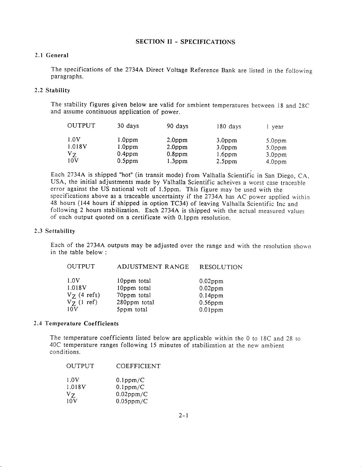
2.2
General
The
specifications
paragraphs.
Stability
of the
SECTION II
2734A
Direct
.
SPECIFICATIONS
Voltage
Reference
Bank
are
listed
in
the
followine
The
and
Each2734A
USA, the initial
error against
specifications
48 hours
following
of each
2.3
Settability
Each
in
the table
stability figures
assume continuous
OUTPUT
l.0V
l.0l
8V I
Y7
lOV
is shipped
the US national volt
above
(144
hours if
2 hours
output
of
the
2734A
below :
given
below are
application
30 days
l.Oppm
.Oppm 2.0ppm
0.4ppm
0.5ppm l.3ppm
(in
"hot"
adjustments made
as a traceable
shipped in
stabilization.
quoted
on
outputs
a certificate
may
transit mode)
of
option TC34)
Each 2734A
be adjusted
OUTPUT ADJUSTMENT
valid
for
power.
of
90 days
2.0ppm
0.8ppm
by Valhalla
l.5ppm.
uncertainty
with
0.lppm resolution.
RANGE
ambient
temperatures
180
3.0ppm
3.0ppm
l.6ppm
2.5ppm
from
Valhalla
Scientific
This figure
acheives
if the 2734A
of leaving
is
shipped
over the range
with
RESOLUTION
days
Scientific
may
be used
has
AC
Valhalla
the
with
and
between
in
worst
a
with
power
Scientific
actual measured values
the
l8
and 28C
year
I
5.0ppm
5.0ppm
3.0ppm
4.0ppm
San Diego,
case
traceable
the
applied
Inc
and
resolution
CA,
within
shorvn
2.4
Temperature
The
40C
conditions.
l.OV
l.0l8v
Y7
Y7
refs) 70ppm
@
ref)
Q
lOV
Coefficients
temperature
temperature
OUTPUT
l
OV
I
.018V 0.Ippm/C
Y7
lOV
l0ppm
lOppm
280ppm
5ppm total
coefficients listed
ranges
following
COEFFICIENT
0.Ippm/C
0.02ppm/C
0.05ppm/C
total
total
total
total
l5 minutes
below
0.02ppm
0.02ppm
0.l4ppm
0.56ppm
0.0lppm
are applicable
of stabilization at
z-l
within
the
the
0 to
new
18C
and
ambient
28
to
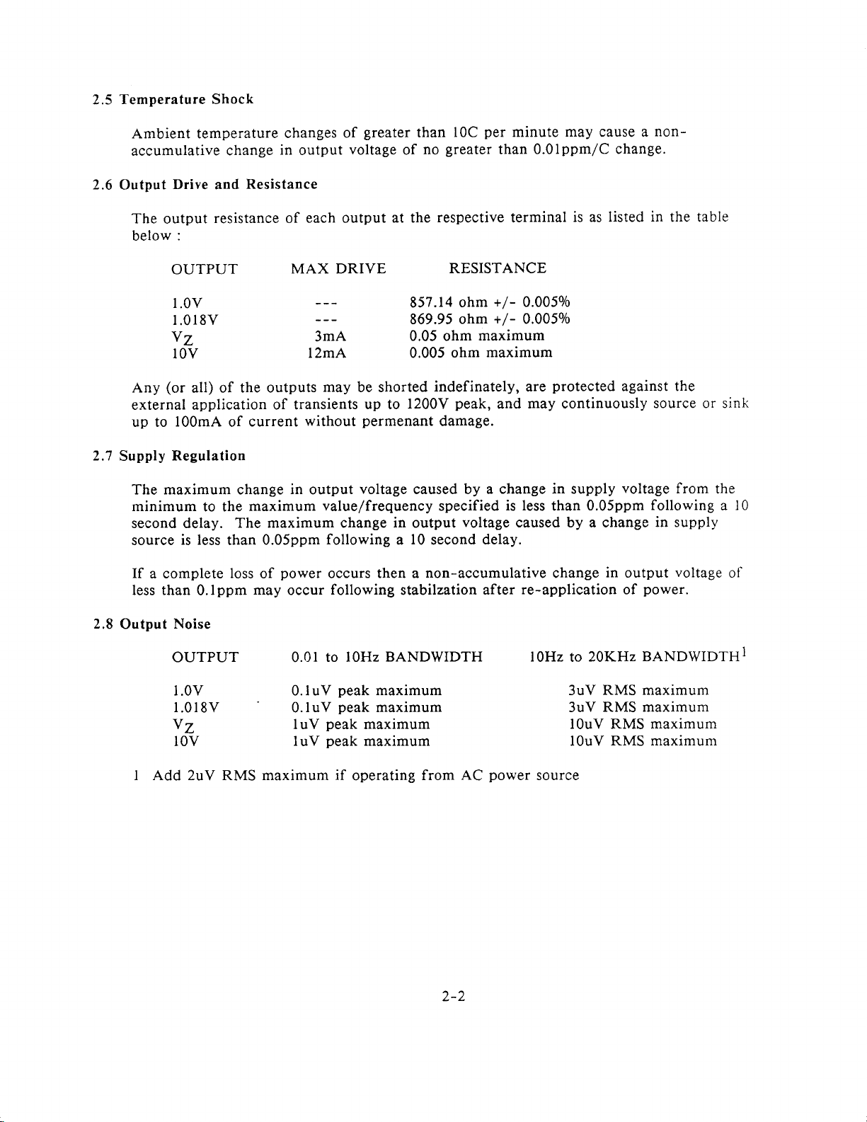
Temperature Shock
2.5
Ambient temperature
accumulative
The
output
below
Drive
:
2.6
Output
OUTPUT
l.OV
l.0l8v
Y7
lOV
(or
Any
external application
up to
2.7
Supply
The maximum change
minimum
second delay.
source
all) of
l00mA
Regulation
is less
greater
changes
change
and
resistance of
in
Resistance
output
of
voltage
each output at the
MAX DRIVE
3mA
l2mA 0.005 ohm
may
the outputs
of transients
current
of
to the
maximum
The maximum change in output
than
without
in
output
0.05ppm
be shorted
up to
permenant
voltage
value/frequency specified
following
than
greater
no
of
respective
RESISTANCE
857.14
869.95
0.05 ohm
indefinately,
1200V
damage.
caused by a
l0
a
second
per
l0C
ohm
ohm
maximum
maximum
peak,
voltage
delay.
minute may cause
than 0.0lppm/C
terminal
+/-
0.0050/o
+/-
0.0050/o
are
may continuously
and
change in supply
is less
caused by a change
is as listed
protected
0.05ppm
than
non-
a
change.
in
the table
against the
source or sink
voltage
following a l0
in supply
from the
2.8
If
a complete
less than
Output
Noise
loss
0.lppm
OUTPUT 0.01
l.0V 0.luV
l.0l8v
Y7 luV
lOV
I Add 2uV RMS maximum
power
of
may occur
0.luV
luV
occurs
following
then a non-accumulative change
stabilzation
after
to l0Hz BANDWIDTH
peak
maximum 3uV
peak
maximum 3uV
peak
maximum
peak
maximum l0uV
if
operating
from
AC
power
in output
re-application
l0Hz
20KHz
to
RMS maximum
RMS maximum
l0uV RMS maximum
source
voltage
power.
of
BANDWIDTHI
RMS maximum
of
,ta
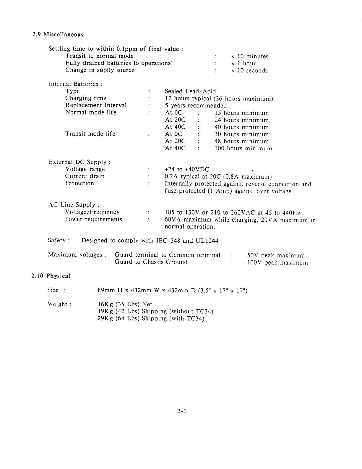
2.9 Miscellaneous
Settling
Internal Batteries
time to
Transit
Fully
Change
TYPe
Charging time
Replacement
Normal mode life
to normal mode
drained
in
Transit mode
External
AC Line
DC
Supply :
Voltage range
Current drain
Protection
Supply :
Voltage/Frequency
Power requirements
within
batteries to
suplly
:
Interval
life
0.lppm of
operational
source
final value
Sealed
l2
hours
years
5
At
OC
:
Lead-Acid
typical
recommended
At 20C
At 40C
At
0c
At 2OC
At 40C
+24
to +40VDC
0.2A typical
Internally
protected
fuse
105
to l30V
60VA maximum while
normal
operation.
:
:
:
(36
l5 hours
24 hours
40
30
48 hours
100
at 20C
protected
(l
Amp)
or 210
<
l0 minutes
<lhour
<
l0
seconds
hours maximum)
minimum
minimum
hours
hours
(0.8A
against reverse
to
minimum
minimum
minimum
hours minimum
maximum)
against
260VAC
charging, 20VA
over
at
connection
voltage.
45
440kIz.
to
maxinrunr
ancl
irr
Safety : Designed
Maximum voltages
2.10 Physical
Size :
Weight
: l6Kg
to comply
:
Guard terminal
Guard to
89mm H x432mmW
(35
t9Ke
Q2
29Ke
(64
with
Chassis Ground
Lbs) Net
Lbs)
Shipping
Lbs)
Shipping
IEC-348
and IJL|244
to Common
terminal
x432mm D(3.5"
(without
(with
TC34)
TC34)
z-)
: 50V
: l00V
x 17" x 17")
peak
peak
maximum
maximum
2.1 1 Environmental
Temperature
Range
: Operating : 0 to
Storage :
Humidity
Altitude
: 0 to 95o/o
0 to
-1000
700/o
to
RH
at temperatures
RH
at temperatures
10.000 ft.
Vibration Per MIL-T-28800C, Type III,
2.12 Recommended
The
calibration interval for
maintain.
days between calibrations
The
Calibration
user should
Interval
the 2734A is
consult the accuracy tables
to obtain the required
40C
+
to
-20
dependent on the accuracy the user
60C
below 35C
between 35
Class 5, Style
in 2.2
accuracy.
40C
and
E
to determine
the
wishes
number
to
of
L-.+
3.1 General
This
utility
3.2
Option
section
of
the
BBL
describes
2734A.
SECTION
several
III
AVAILABLE
-
options available
from
OPTIONS
Valhalla
Scientific
to increase
the
Option BBL
with
recommended
3.3
Option RSK-3
Option RSK-3
of a 2734A
recommended
3.,1
Option RX-3
Option
rack.
3.5
Option
Option
gold plated
acuuracies
3.6
Option
This
years
is
dual
banana
whenever
in
an equipment
that
RX-3
SL-48
SL-48 is a 48
SP-2
option
of
provides
copper
greater
of
provides
operation.
a dual
is
plugs
heavy
a
shielded
of the highest
option RSK-3
all
inch
spade
than
a selection
cable
accuracies
duty rack
rack.
parts
required
long
shielded
lugs.
0.5uV
The
are desired.
of the most likely
equipped with
quality
greater
of
slide kit which
Option RX-3
factory
be
installed.
for mounting
cable
use
of this
banana
and low
than luv
allows
rack
terminated
option is recommended
parts
plugs.
leakage.
are
ears
This
desired.
simple mounting
are
also
the 2734A
at
each end
fail
to
during
in
It is
48 inches
cable
is
and removal
recommended.
a l9 inch
by
whenever
the first
high
equipment
quality
two
long
It is
3.7 Option
This
2734A.
repeated
TC-34
option
provides
The
use of this
transportation
rugged
a
option is
or
carrying
strongly recommended
whenever
the
case
and rechargeable
utmost
transfer
3-l
battery
if
accuracv is
the
2734A
supply for
is
to
be used for
desired.
the
4.1
General
This
section
user is
the 2734A.
The
figure
J.1.1
"CHASSIS
This
whenever
ground
2734A
.1
.1.2
''''TRANSIT MODE''
This
for
advised
paragraph
4-
terminal is
connection.
is
LED
details).
SECTION
outlines
to read
numbers
l.
GROUND"
connected
the 2134A
It
operating
is illuminated
This
from DC
LED
LED
IV
- FRONT
the
use
of each
Section
used in
Terminal
VI
this
to
directly
is
operated
is
also recommended
whenever
being illuminated
from
supply
PANEL
of the front
obtain
section
to
the chassis
AC
line
(internal
the 2734A
indicates
CONTROLS
panel
full
descriptions
correspond
of the 2734A
and
the line
that
this terminal
or external)
is
in
"Transit
that
AND
controls
of the method
to the
the 2i34A
cord
and
Mode"
reference
and
be
no AC
CONNECTORS
and
connectors,
to
numbers
should
does
grounded
1r."
is not
be
not
contain
line
cord is
S..tions
ready
whenever
the
operate
used in
grounded
a
presenr.
V
and
for
use
the
VI
{.I.3
4.1.4
.I
.I.5
,{.1.6
''BATTERY
This
LED is illuminated
(from
not have
''OVEN
This
temperature
not
temperature
use
in
''AC
This
switch
"BATTERY
This
the
indicates
invalid.
the AC
sufficient
FAULT''
LED
yet
settled from
if
this LED is
the
"Transit
ON'' LED
LED is
(on
LED
minimum
that the 2734A
is illuminated
the rear
O.K." LED
is illuminated whenever
CHARGING''
supply).
charge
LED
by more
high
regulation
LED
whenever
This LED
to maintain
whenever
than
5C. This
storage temperatures
circuitry is faulty.
illurninated.
Mode".
illuminated whenever
panel)
required
for
is not
is
in the
correct
ready
the internal
being illuminated
the
battery life
the internal
LED
being illuminated
Whichever
This
LED
is
always
position
for
use
power
of the 2134A.
and that
an AC
ON
the internal
operation
batteries
oven temperature
or, if
source is
(see paragraph
batteries
in
the 2i34A
indicates
specifications
the condition
the
extinguished whenever
that the
indicates
cause
present
or external
This
LED
the
are
internal
paragraph
in
exceeds
that
prevails,
the 2734A
and
the AC
5.1.1).
DC
supply
LED
being
indications
being
charged
bateries
2.9.
the regulation
the 2134A
the
internal
is
not ready
the 2734A
power
exceeds
extinguis6ecl
may
be
clo
has
for
is
4-l
4.1.7
''OVEN
READY''
LED
This LED
final
is illuminated
value. This LED being extinguished
4.I.8''CALIBRATION
This removable
details.
4.1 .9
"1.0V",
These terminals
"1.018V",
internal circuitry
whenever
ACCESS COVER''
gives
cover
"Y2",
provide
access to the
"10Y", "COMMON"
voltage
the
within the 2734A
internal oven
the
indicates that
calibration
and
outputs
from
from common
temperature
the
adjustments.
"GLIARD"
2734A and the
the
voltages.
mode
within
is
2734A
Terminals
is not ready
See section
0.5C of
means to
for
VIII
guard
its
use.
for
the
4-2
5.1
General
SECTION V
REAR
-
PANEL
CONTROLS
AND
CONNECTORS
The functions
paragraphs.
5.1.1
"INSTRUMENT
This
power
is
depressed,
selection is 105
lowermost.
connector,
5-2 for
5.1.2
"OVEN
This
reduces
unit
"OPERATE"
5.1.3
"EXTERNAL
The
to the 2734A.
voitages
of the rear
The
connector
ON/OFF
contains the
switch and fuses.
and
to l30v
The
selection may
this is
details
MODE"
switch selects
the internal
while
terminals
on these terminals.
on changing
Switch
maintaining
mode must
BATTERY"
provide
The
paragraph
POWER"
is
in
the OFF
if
also
the case if
either
power
power
be selected
the means
provides
fuse
panel
controls
numbers
Connector
AC
correspond
power
The
position
connector,
'll0-120v'is
only be made if
the fuses
the fuses
"Transit Mode"
consumption
to, and
Terminals
or line voltage
the temperature
whenever
and
which
by
protection
and
connectors
to the reference
AC
power
AC
if
the
lowermost,
are
switch is
"0" is
the
to be
or "Operate
of the 2734A
it is
desired
"FUSE"
an
external DC
for
the internal
are
power
depressed.
and is 210
power
cord is not
changed
selection.
Mode"
to
extend
of,
the
to tise
power
described
voltage
in
the
in
numbers
selection
position
ON
The
AC line voltage
to 260v
inserted
or inspected.
of operafion.
the battery
internal
circuitry
references.
the 2l34A.
source
against
the following
Fieure
of
switch,
if
the " l,'
,,220-240y,,is
if
into
the
See figure
Transit
life
may
mode
of
the
The
provided
be
excessive
5-1.
AC
5-l
6.1
General
SECTION VI
MANUAL
-
OPERATION
This
transportation
between laboratories.
6.2
Power
The
of sufficient
require
from
Inspection
virtually
power
6.3 When
The
i)
AND
ii)
AND
section
Connections
2734A
one
source for
is
2734A
The BATTERY
The
provides
methods recommended
has
internal
external AC
it)
from
the AC
power
unaffected
of the
source
specifications
the application.
the 2734A
is ready
OVEN READY
information
batteries
power
to
by the
Ready
for
use
O.K. LED
DC
or
input
another is
(see
power
for
Use?
whenever
LED
is illuminated
regarding
for
use
to maintain
power,
these
if it
is
automatic
Section II)
source,
thus
the following
is illuminated
the
normal
of
all
batteries
connected
2734A
the
circuitry within
and turned
and virtually
shows
the
that
user may
conditions
use of the 2734A
in
transfer
are automatically
measurements
the unit
ON. The
transient
the accuracy
select the
exist
free.
most
:
and the
in
the
charged
switch
2734A
convenient
absence
(if
js
thel'
over
iii)
AND
iv)
AND
v)
6.,1
Using the
The
GUARD
"box"
It
should
being
the COMMON
connect
DISCONNECTED
The
OVEN FAULT
The TRANSIT
The
CALIBRATION
GUARD
Terminal
terminal
completely
always
operated in
surrounding
be connected
excessively
terminal
this terminal
WHEN
LED
is
extinguished
MODE
LED is
ACCESS
on the front
the reference
to a low impedance
electrically
of the 2734A
to chassis
ground.
USING THE 2734A.
extinguished
COVER is in
panel
of the 2734A
and
noisy
will
environments.
be sufficient,
NEVER
6-l
place
output
node,
LEAVE
is internally
amplifier
circuitry
particularly
In
however
THIS
TERMINAL
connected
if
general
it may
to
of the 2:'34A.
the 2i34A
connection
be necessary
a
js
guarcl
to
to
6.5
Making
Connections
to the
27344
The
terminals on
thermal emfs are
in the connections
and/or act as
equipment, the
particularly
air,
wires
are
point
to the terminals.
heat
good
conductors
2734A
the
reduced to the
to the terminals
conductors
internal
if
temperature of
unit
the
of heat then thermal emfs can
Thus the
is near
i) Accuracies in excess of
ii)
Accuracies
iii)
Best
The
user should
impedance
output
very
possible
milliohms).
levels,
low impedances
performance
possible
in
excess of 0.5uV
accuracies
note that the type i)
levels
(typically
type
ii)
cable offers
(typically
at the cost of ease of use
5 to 25 milliohms)
made from high
are
possible.
least
if the
to or
wires
from the
the 2734A
to an air-conditioning
following
luV
3 to
: Good
cable offers ease of
good general purpose
l0 milliohms),
quality gold
Thermal emfs can
used are
terminals.
is higher
plated
not made
with
As
than
duct, thus
produced
be
wires
connection
quality
used.
and
quality
pair
wire.
good
Good
shielded cable.
Twisted
solid copper conductor,
coated
while
impedance
and
types are
"dual"
copper spade
24AWG
of
use and relatively low
performance
use at all
iii)
type
levels
tellurium copper, thus
however
pure
from
piece
any
that of the surrounding
produced
be
copper
of electronic
if the connecting
at the
recommended :
banana
(or
Teflon
at the V7
voltage
cable offers the
(typically
contact
leads mt1,
type
lug
terminated
smaller)
(or
levels and
25
high
simular)
l0V
and
best
200
to
be
prritr
Transportation
6.6
There
range of methods for
are a
of the output
described
than
precautions
6.6.1
Short-Range Moiements
For
provided
this type of
that the
CHARGING LED
movement). For
minimal
soon as the
temperature
below. Using
0.lppm can be achieved, if less
need
movements within
short
within
batteries
stabilzation time is required
OVEN
of the
voltage
2734A
specifications, the
these
taken.
be
(no
2734A
the
movement,
have
this
thus no
sufficient charge for
is
extinguished
type
READY LED
differences are
transporting
various
methods
temperature extremes, less than t hour)
a building the internal
provided
are
special
movement
of
encountered then
of shipping 2734A's transfer
accuracy and integrity is required
for
precautions
the
powered
when
it is not necessary
when
the
is illuminated
2734A
the
methods for
protection
are necessary
movement
from AC line
2734A reaches its final
the
will
this
while
each type of movement
batteries and thermal
against
(check
to select
2734A is ready
immediate).
be
maintaining
accuracies of better
loss
of integrity during
other than ensuring
the
then less
lagging
that the BATTERY
prior
to disconnection
TRANSIT
destination
for
if no major
use,
integrit)'
are
and
mode, thus
(as
6-2
6'6.2
Short or Medium-Range
For
short
or
changes
the movement
internal
or
adverse
battery
is recommended
6.6.3
shocks
excellent).
from
ready
minutes,
Long-Range
For
long range
power
AC
then
wrapping
by
Upon reception
power
AC
for
use as
immediately
for
precautions
the
followed with
also recommended
withstanding
Scientific
then
the
trunk,
extremely wide
the 2734A
mark receiving
soon
shipping
it is recommended
and should not
is
possible)
as
Movements
medium
may
range
weather
take
over one hour
supply may
that the
unit
it in weather
as
soon as
soon as
Movements
movements
extended
indicated
the
addition
that
typical shipping
container for
range
not
be
"personally" transported
intructions
on the exterior
possible
the OVEN READY
if
the conditions were
(less
or
periods
of the
the 2734A
that
be
of temperatures
(i.e.
(exposure
movements
conditions
where
(i.e.
(but
still
be used
be shielded
proof
of the 2734A
to recharge
than
30 hours)
whenever
of time
for
medium
selection
be
shipped in
shocks
it is
left
(it
purpose).
this
placed
in
the
and humidities
instructions
of
the shipping
to
ambient
the 2734A
movement
definitely
and TRANSIT
from
the
material
after the
the internal
LED
not
possible
it is
(but
less
range
from
less
weather
(plastic
movement
is illuminated (typically
severe).
that the 2734A
than
30 hours,
movements
of TRANSIT
a
shipping
is recommended
If
the 2734A
in
vehicle
passenger
the
overnight,
then it is
to unpack
container.
present
recommended
the
changes,
may
be exposed
one building
than
l8 hours)
mode is
"bubble
MODE
that
compartment,
unit
unnecessary,
conditions
pack"
the unit
batteries,
e.g. between
(6.6.2
afove)
prior
container
the user retain
is to
transported
protect
to
in
the
and apply AC
less
than
12 hours)
to large
to
another)
then
the
however
and temperature
material
should
the 2734A wili
be
within
may
be left without
facilities)
should
to shipment.
capable
of
the
in
rather
the 2734A
trunks
that
than in
of cars.
the user
power
ambient
or
is
powered
be
1
or 2
be
It is
Valhalla
a car
from
If
clearly
as
it
the
NOTE
(E.G.
RECOMMENDED.
6.6.4 Long-Range
For
user
the
when
damage
should have
Very
6.6.5
The
minimum
the
2134A
Center
the four
reception,
: IF
AIR
very
long
should
carrying
powered
and
Long-Range
2134A
of user
performance.
then
prior
internal
if
THE TRAVEL
TRAVEL
Movements
range
place
case have
thermal
movements
the 2734A
from
AC
shock,
TRANSIT
Movements
has
been designed
support, however
If very
the user is recommended
to
shipping
references
any reference
MAY
DELAYS
(less
BE
DUE
than
or
in
an
been fully
power).
MODE
charged
The
powering
while
selected if
and/or
withstand
to
adverse conditions
2734A.
the
prior
to
movement
DELAYED
TO
SNOW ETC.)
6 days)
whenever
option TC-34
the
(neither
option TC-34
the 2734A
the transit
Very
Adverse
very
a
some conditions
are expected
to consult
The
user
shipment
does
the nearest
may
and then
occur it is
6-3
BY
PREVAILING
THEN
utmost integrity
carrying
has
unit
offers
for
THE
case where
a CHARGING
protection
the entire
time is longer
Conditions
wide
range
of temperatures with
may
adversely
during
Valhalla
wish
to individually
compare
extremely
WEATHER
PROCEDURE
is required
both
the unit
against
(the
time
rhan 3
days).
then
LED
shipping
illuminatecl
2i34A
CONDITIONS
affect the integrit)'
transportation
Scientific
measure
of the
Service
each
their measurements
unlikely
that
all four
IN
the
ancl
6.6.4 IS
a
of
of
upon
references
voltage
references
Section VIII)
will
can be
themselves,
be affected,
maintained
at the
receiving
no
integrity
major
thus the
since
the other outputs
end.
of the absolute
elements effect
can then be ratiometrically
value
this output other
of the Y7
than the
calibrated
output
(see
i) Possibility
The internal
temperatures
amplifiers. However,
temperatures
source used
Nickel-Cadmium
are recommended. The
conditions,
the 2734A.
Possibility
ii)
Experience with
85C may
damaged
remove
direct
air temperature
cause
Possibility
iii)
The
between 24Y
operation
construct
(or
storage)
becomes ineffective
output
measurements.
cause
by such extreme
the internal
sunlight
surfaces
of extended
external DC
for inputs
any
voltage
very
of
low
circuitry is
low
as
as
temperatures
ovened
-40C
the internal
thus they
to maintain
should be
the
batteries have
possibility
thus the user is
very
of
high
temperatures
semiconductor
in
shifts
while
does not
their
batteries
being transported
to exceed
time
and
power
40VDC
input
down
power
source if
of the 2734A
then
of 0.lppm
(e.g.
travel in
when
even
will
not
adversely affect
lead-acid
removed
internal
excellent
temperature during movement.
and
performance
of extreme temperature
strongly recommended
(e.g.
travel in the
references
voltages,
temperatures.
and
to ensure that
attain these
even l00C in
periods.
may
be
and
the internal
I5VDC
to
length
the
becomes
the
which
extensively
2734A
is
adaquate for
is
has
also
Thus
in
these
very
high
these
connected to
circuitry of
under normal
of the
specified
Polar regions).
the
in TRANSIT
the
batteries
some
will
form
at sub-zero temperatures
to
thoroughly
equatorial
shown
the
that temperatures in
internal
the user is
2734A
the
conditions
temperatures
conditions).
any convenient
the
conditions,
journey
extended
yield
to
all
but the most
mode,
references
thus
even
and
withstand
not
of external DC
outpur
these
power
Lithium
shock
lead-acid
strongly recommended
is mainatined
(in general,
2734A will
is known.
and
worst
a
exists in these
thermally insulate
desert regions).
batteries may
the ambient
but
direct sunlight
source
maintain
thus the
If
the
power
the
case change in
decerning
source
excess
away from
of
user
journey
of
or some
and
of
be
to
can
power
may
Typical
6.7
Connections
of this
connected in
internal
bCSt iN
POTENTIALS,
Connection.s
and
typical usages
section. The
series
battery
PCTfOTMANCC
supplies
CARE MUST
and
Usages
user
should note
of
the
2734A
that
to obtain higher voltages
and the
(NOTE
THIS
-
BE
CHASSIS
MAY
TAKEN).
are
shown in
two
(or
units
terminals
when
then the
GROUND
CAUSE THE
6-4
various
the
more)
2734A
should
left
CHASSIS
figures
units
are
powered
be
open circuit
TO HAVE
at the
end
by their
for
the
DANGEROUS

THIS
SECTION
SECTION VII
IS INTENTIONALLY
REMOTE
-
LEFT BLANK
OPERATION
FOR
PROPOSED
FUTURE
DEVELOPEMENT.
7-l
8.1
General
SECTION VIII
- CALIBRATION
The 2734A
and
switches is made
Removing
8.2
panel.
preserve
A
calibration certificate
calibration
the Calibration
To remove
about 1/8".
ensure that
holes in
until they
8.3
Calibration Following
If
elapsed
range.
shorting
made
enclosure
General
8.4
The
on user
the front
are seated.
a component
since the factory
The
plugs
removing
by
top cover
Calibration
calibration
requirements
is
calibrated with
by
integrity.
the calibration
Pull
evenly
plungers
panel
has been replaced,
range
on the
on the two
are in the withdrawn
and
Component Replacement
of the
resistor
the
upper front
and then the
Philosophy
of the 2734A
:
the covers
removing
Cover
access
gently
calibration,
potentiometers
the calibration
sticker may
cover,
plungers
press
damaged
the
banks in
bezel,
upper insulation
can
be acheived in
Access
on.
be
gently pull
to remove
position.
the
cover into
by
calibration
may
be moved
reference
the
instrument
the
to the
access
placed
over the
out
the two
Line
misuse,
or
potentiometers
by changing
enclosure.
covering
one
of three
adjustment
port
cover
located
access
plungers
the
cover.
the
place.
long
a
top
cover, the reference
(see
To replace
grommets
Push
the two
period
may
Access
figure
differing
potentiometers
on
port
cover
on the
the cover,
with
up
plungers
of time
not
have
positions
the
to these
8-l).
ways,
dependant
the front
to
cover
the
has
enough
of the
plugs
in
is
i)
For most
necessary
2734A,
case it is not necessary
necessary
is
dependant
method
ii)
Where it is not
voltages (similar
be checked
the
averaging
ACCESS
will
is
outlined in
iii) When
nominal
potentiometers
usages
it
used by Valhalla
COVER
required.
be
it is required
or
removed.
8.7
below.
and for routine
to actually correct
is
to
required
only
measure
personal
on
to exactly "know"
remove
to
the
actual output
preference
Scientific Inc.
necessary
to
measurements
then
i)
above)
to adjust
of these "cells"
must
be
procedure
The
paragraph
realign
will
procedure
The
8.6 below.
to correct for
individual
the
required
be
which
periodic
for
any deviations in
the
CALIBRATION ACCESS
voltages.
and the
the outputs
but the
integrity
of each individual
will
be required.
removed,
however no
which
deviations
reference
and the
Valhalla
8-l
calibration
and record
equipment
is
outlined in
of the 2734A
Valhalla
of the actual
"cells"
of the 2734A it
the
output
the
procedure
The
available however
paragraph
to exactly
reference "cell"
In
this case the
adjustments
Scientific Inc.
then adjustments
the correct, nominal,
output
voltages
actual
absolute
CALIBRATION
of the
uses
CALIBRATION ACCESS
Scientific
Inc.
uses is
outlined in
is not
of the
values.
COVER, it
performing
for
the
8 5 below.
voltage
and
checking
potentiometers
perform
to
voltages
of the
COVER must
from
internal
paragraph
In
is
is
this
only
this
ro
of
this
the
be
 Loading...