


www.valex.com
Specification Number SP-9217
Valex High Purity Ball Valve
SECTION DESCRIPTION PAGE
1.0 Scope .........................................................................................................................................2
2.0 Reference Documents ...............................................................................................................2
3.0 Material Characteristics ............................................................................................................2
4.0 Operating Data ..........................................................................................................................3
5.0 Final Process .............................................................................................................................4
6.0 Testing and Inspection ..............................................................................................................4
7.0 Packaging ..................................................................................................................................4
8.0 Marking and Documentation ....................................................................................................5
9.0 Supplementary Features ............................................................................................................5
10.0 Ordering Part Number System .................................................................................................6
11.0 Revision Log .............................................................................................................................8
This document is presented by Valex Corp. for general information purposes and may be reproduced in part or
total. In total, the document reflects the specification requirements met or exceeded by Valex products sold under
the name "Valex High Purity Ball Valve".
SP-9217 Rev. X, Page 1 of 8

1.0 Scope:
Configuration: Ball valve.
Sizes: 1/4” o.d. to 6” o.d. (6.4mm o.d. to 152.4mm o.d.)
JIS 15A to 100A pipe (21.7mm o.d. to 114.3mm o.d.)
2.0 Reference Documents:
General Note: All specification references shall be taken as the latest editions, including appendices,
addenda, errata, and revisions.
ASTM A351/A351M, Standard Specification for Castings, Austenitic, Austenitic-Ferritic
(Duplex), for Pressure Containing Parts.
ASTM A479/A479M, Standard Specification for Stainless Steel Bars and Shapes for Use in
Boilers and Other Pressure Vessels
ANSI/ASME Specifications: ANSI/ASME B46.1, Surface Texture.
Crane Technical Paper: TP-410 Flow of Fluids
CGA Specifications: CGA G-4.1, Cleaning Equipment for Oxygen Service.
ANSI/ASQC Standard: ANSI/ASQC Z1.4-1993 Sampling Procedures and Tables for Inspection by Attributes
3.0 Material Characteristics:
ASTM Reference: Body Housing: ASTM A351-CF8M.
End-Cap Flanges: ASTM A351-CF3M.
Ball: ASTM A351-CF3M or A479 316/316L
Materials of Construction: Wetted Path: CF3M / 316 stainless / 316L stainless.
Non-Wetted: CF8M, 300-series stainless steel, vinyl (handle sleeve), tamper-evident
ink (on bolt threads).
Standard seats/seals: Reinforced Teflon (RTFE) seats, virgin Teflon (PTFE) seals.
Other seat/seal materials are available.
Internal Surface Roughness
Wetted Path: 25 micro-inch maximum.
Assembled Length Tolerance: Per brochure ± .25” (± 6.35mm)
Lubricant: None
SP-9217 Rev. X, Page 2 of 8
Valve Size
Ball Orifice
Connection Orifice
Cv1
(Inches)
(Inches)
1/4" X .035"
0.402
0.180
2.9
3/8” X .035”
0.402
0.305
9.0
1/2” X.049"
0.402
0.402
16.3
3/4" X.065"
0.620
0.620
41.2
1" X.065"
0.870
0.870
84.9
1-1/2" X.065"
1.370
1.370
223.3
2" X.065"
1.870
1.870
432.3
2-1/2" X.065"
2.370
2.370
714.4
3" X.065"
2.870
2.870
1071.2
4" X.083"
3.834
3.834
1975.3
6" X.109"
5.782
5.782
4697.8
JIS 15A (5S)
0.870
0.724
57.4
JIS 20A (5S)
1.370
0.941
100.4
JIS 25A (5S)
1.370
1.209
171.1
JIS 32A (5S)
1.870
1.551
290.7
JIS 40A (5S)
1.870
1.783
391.0
JIS 50A (5S)
2.370
2.252
641.1
JIS 65A (5S)
2.870
2.839
1046.5
JIS 80A (5S)
3.834
3.343
1478.4
JIS 100A (5S)
4.335
4.335
2559.3
1/4" - 1" 1-1/2" - 2" 2-1/2" - 4" 4.5" 6"
15A 20A - 40A 50A - 80A 100A
-20 1000 800 500 400 300
0 1000 800 500 400 300
100 1000 800 500 400 300
350 0 0 0 0 0
Temp (F)
Pressure (PSIG)
0
100
200
300
400
500
600
700
800
900
1000
1100
1200
-50 0 50 100 150 200 250 300 350 400
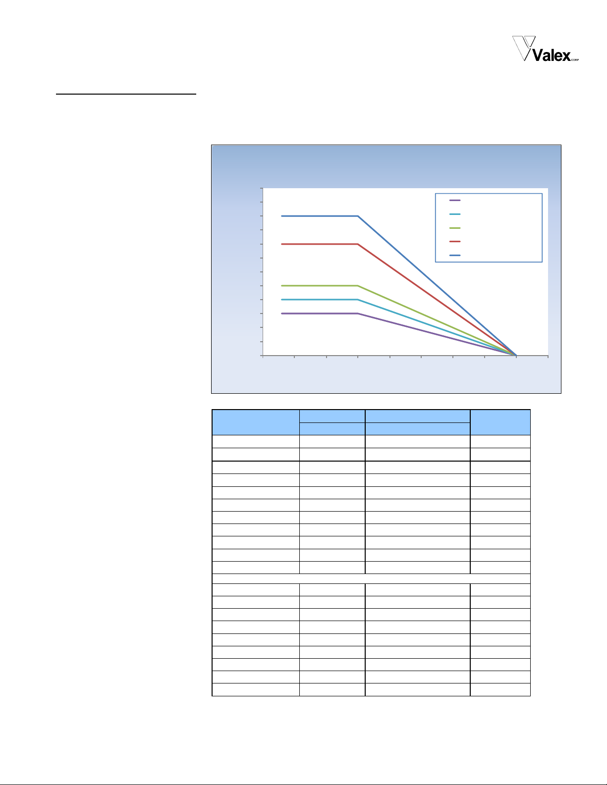
Maximum Working Pressure
(PTFE Seats / Seals )
6"
100A
2-1/2" - 4" (50A - 80A)
1-1/2" - 2" (20A - 40A)
1/4" - 1" (15A)
Temperature (°F)
Pressure (PSIG)
4.0 Operating Data:
Temperature Range: -20°F to 350°F as dictated by standard seat/seal materials. Seat/seal materials other
Maximum Working Pressure:
Flow Coefficient Data:
than standard may affect the working temperature range.
1) Flow coefficient data calculated using methods described in Crane Technical Paper TP-410.
SP-9217 Rev. X, Page 3 of 8
 Loading...