

Page 1

- 1 -
Motozappa a benzina
ISTRUZIONI D’USO
ATTENZIONE! Prima di usare la macchina, leggete attentamente le istruzioni per l’uso
Petrol tiller
OPERATING INSTRUCTIONS
CAUTION! Before starting the machine, read the operating instructions carefully
ATTENZIONE! Prima di usare la macchina, leggete attentamente le istruzioni per l’uso
CAUTION! Before starting the machine, read the operating instructions carefully
1497604
20.06.2016
Page 2
- 2 -
A
16
7
18
1
3
4
8
10
17
19
13
14
15
11
12
5
6
9
2
Page 3
- 3 -
B
Ca
Cb
Cc
3
1
2
2
Senso di chiusura
della molla
7 8 96
5 10
17
14
15
16
13
11
3
2
1
12
4
Page 4
- 4 -
D
x6
1
E
3
1
2
Page 5
- 5 -
Fa
1
Fb
2
1
4
4
1 2
6
5 3
4
Sinistra
Destra
2
1
1
Ga
Gb
H
I
L
0,7 - 0,8 mm
3
4
2
1
5
5
3
Page 6

- 6 -
DATI TECNICI
1. Tipo di motore
2. Potenza motore
3. Cilindrata
4. Capacità serbatoio motore
5. Tipo candela accensione
6. Velocità motore a vuoto
7. Larghezza di lavoro
8. Diametro utensili di lavoro
9. Vibrazioni a livello dell’impugnatura
10. Procedura di valutazione della conformità seguita
per 2005/88/CE
11. Ente notificato preposto per 2005/88/CE
12. Livello di potenza sonoro misurato Lw(A)
13. Livello di pressione acustica secondo ISO 3744 Lp(A)
14. Peso macchina
TECHNICAL DATA
1. Engine type
2. Engine power
3. Engine size
4. Tank Capacity
5. Spark plug type
6. Engine speed when empty
7. Work width
8. Diameter work tools
9. Vibrations at grip level
10. Procedure for evaluating conformity enclosed (2005/88/EC)
11. Notified body (2005/88/EC)
12. Measured noise level Lw(A)
13. Acoustic pressure level according to ISO 3744 Lp(A)
14. Machine weight
1 4T
2 4,85 kW
3 196 c.c.
4 2 l
5 TORCH, F7RTC
6 3600 min
-1
7 680 mm
8 280 mm
9 5,046 m/s
2
K=1,5
10 VI
11 TUV Rheinland - Nurnberg
12 96,87 dB(A) K=3
13 87,36 dB(A)
14 45 kg
DICHIARAZIONE DI CONFORMITA’
La ditta indicata in etichetta dichiara sotto la propria responsabilità
che il prodotto ivi citato è conforme ai requisiti essenziali di sicurezza
e salute contenuti nelle seguenti direttive europee:
2006/42/CE, 2014/30/CE, 2005/88/CE
DECLARATION OF CONFORMITY
The firm indicated on the label declares, under its own responsibility,
that the product cited there complies with the essential health and
safety requirements contained in the following European directives:
2006/42/EC, 2014/30/EC, 2005/88/EC
Persona autorizzata a costituire il fascicolo tecnico presso/ The
person authorized to compile the technical file is in
Valex SpA - Via Lago Maggiore 24 - 36015 Schio (VI) - Italy
Schio,
02 2016
Un procuratore - Attorney
ARRIGO ZANELLA
Page 7

- 7 -
i
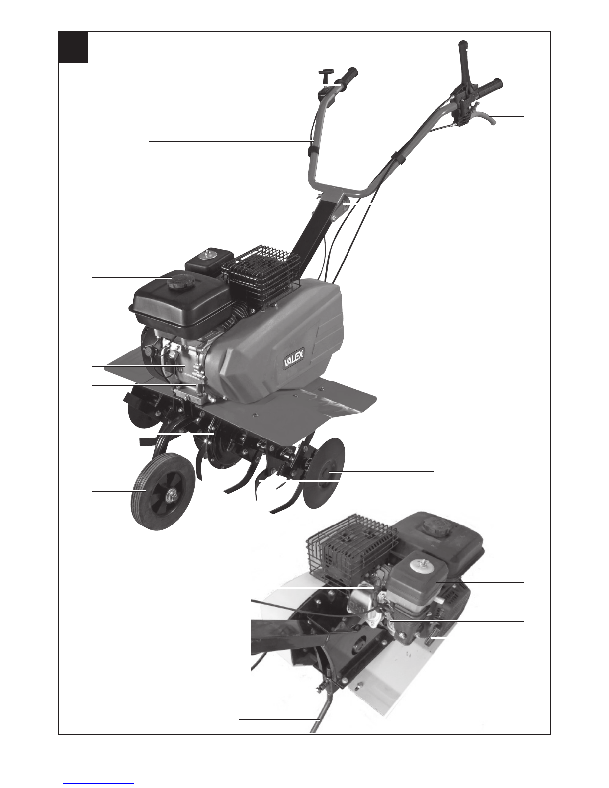
DESCRIZIONE MACCHINA (FIG. A)
1 Manico (stegola).
2 Leva di comando avanti utensile di lavoro.
3 Leva di retromarcia.
4 Spina di regolazione manico.
5 Vite di fissaggio timone.
6 Timone
7 Tappo serbatoio benzina.
8 Tappo olio.
9 Maniglia di avviamento.
10 Motore.
11 Filtro aria.
12 Carburatore.
13 Utensile di lavoro.
14 Ruota per il trasporto reclinabile.
15 Cappuccio della candela e candela di accensione.
16 Leva comando gas.
17 Gruppo riduttore, albero di trasmissione.
18 Comando On/Off.
19 Disco laterale.
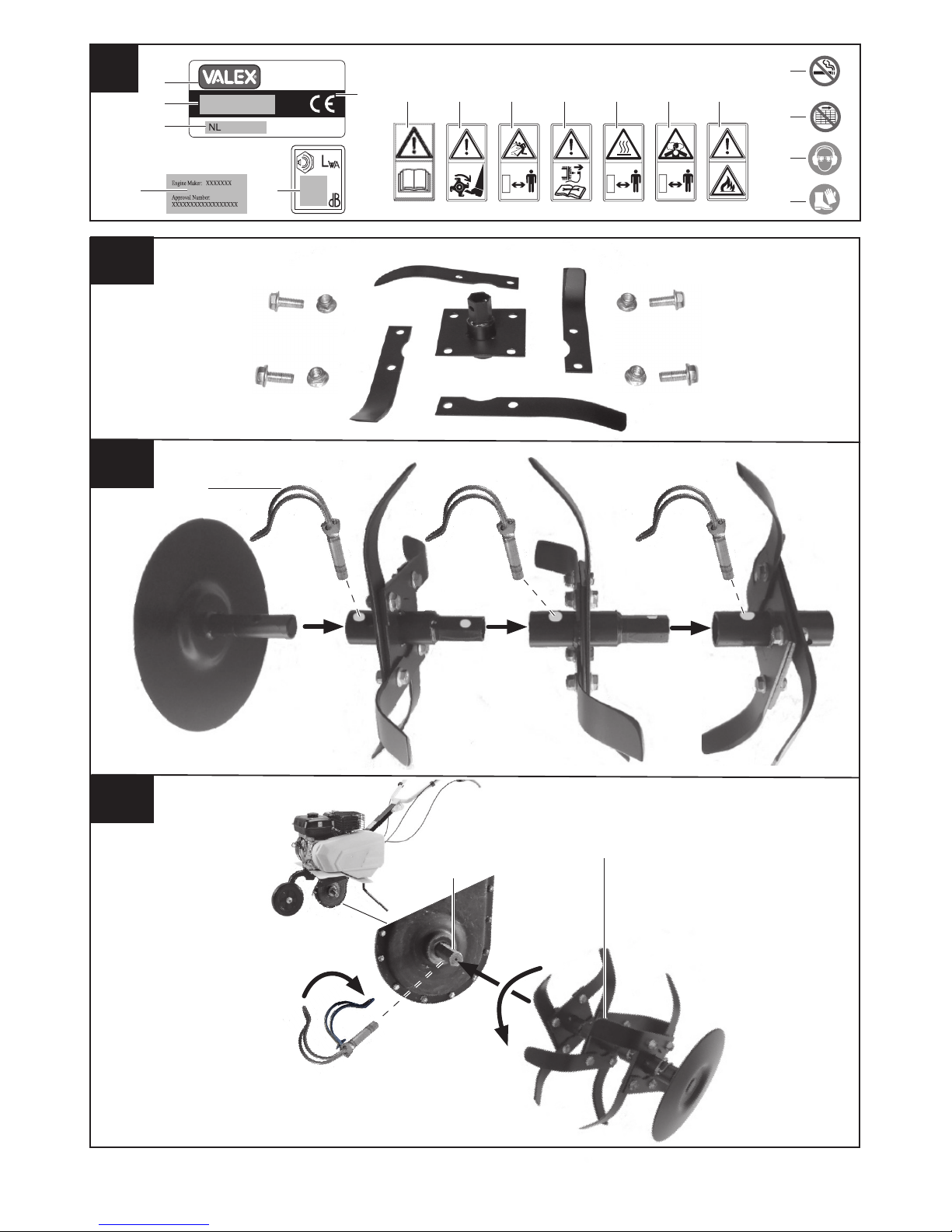
DESCRIZIONE MARCHIATURE E SIMBOLI (FIG. B)
1 Marchio e modello macchina.
2 Dati tecnici.
3 Numero di lotto.
4 Marcatura di Conformità.
5 Attenzione! Leggete attentamente le istruzioni prima dell’uso.
6 Attenzione! Pericolo elementi rotanti, mantenere mani e piedi
distanti dall’area di lavoro finché il motore ruota.
7 Attenzione! Pericolo lancio sassi; mantenete le distanze di sicu-
rezza.
8 Attenzione! Spegnete il motore e scollegate il cappuccio della
candela prima di ogni operazione di regolazione, manutenzione,
pulizia.
9 Attenzione! Pericolo di superfici calde. Alcune superfici esterne
della macchina possono raggiungere temperatura elevata. Dopo
aver spento il motore alcune superfici possono rimanere calde.
Mantenere le distanze di sicurezza.
10 Attenzione! Il motore emette un gas velenoso, inodore e incolore:
l’inalazione provoca nausea, svenimento e morte. Mantenere le
distanze di sicurezza.
11 Livello acustico
12 Marchiatura emissioni motore
13 Non fumare o usare fiamme libere
14 Divieto di togliere o manomettere i dispositivi di sicurezza o di
protezione della macchina.
15 Usare cuffie antirumore e occhiali di protezione
16 Usare guanti e stivali di protezione
17 Attenzione: Infiammabile
MESSA IN SERVIZIO
La macchina può essere fornita con alcuni componenti smontati. Per
il loro montaggio seguite le seguenti istruzioni.
Per l’uso corretto e in sicurezza della macchina è necessario montare
tutti i componenti e seguire attentamente le istruzioni.
Attenzione! Durante queste operazioni indossate i guanti poiché i
componenti metallici potrebbero avere spigoli taglienti.
Montaggio utensili di lavoro (Fig. C)
- Assemblare gli utensili con le viti e i dadi in dotazione (Fig. Ca).
- Assemblare tra loro gli utensili e il disco facendo corrispondere i
fori e montare i perni a molla (Fig. Cb). La molla dei perni (2) deve
essere chiusa rispettando il senso di rotazione degli utensili (Fig. Cc).
- Inserire gli utensili (Fig. Cc pos.1) sull’albero del riduttore (Fig. C pos.
3), fare corrispondere il foro sull’albero (3) con quello degli utensili e
montare i perni a molla (2). La molla dei perni (2) deve essere chiusa
rispettando il senso di rotazione dell’utensile (Fig. Cc).
- Il filo dell’utensile di lavoro deve essere nel verso della rotazione.
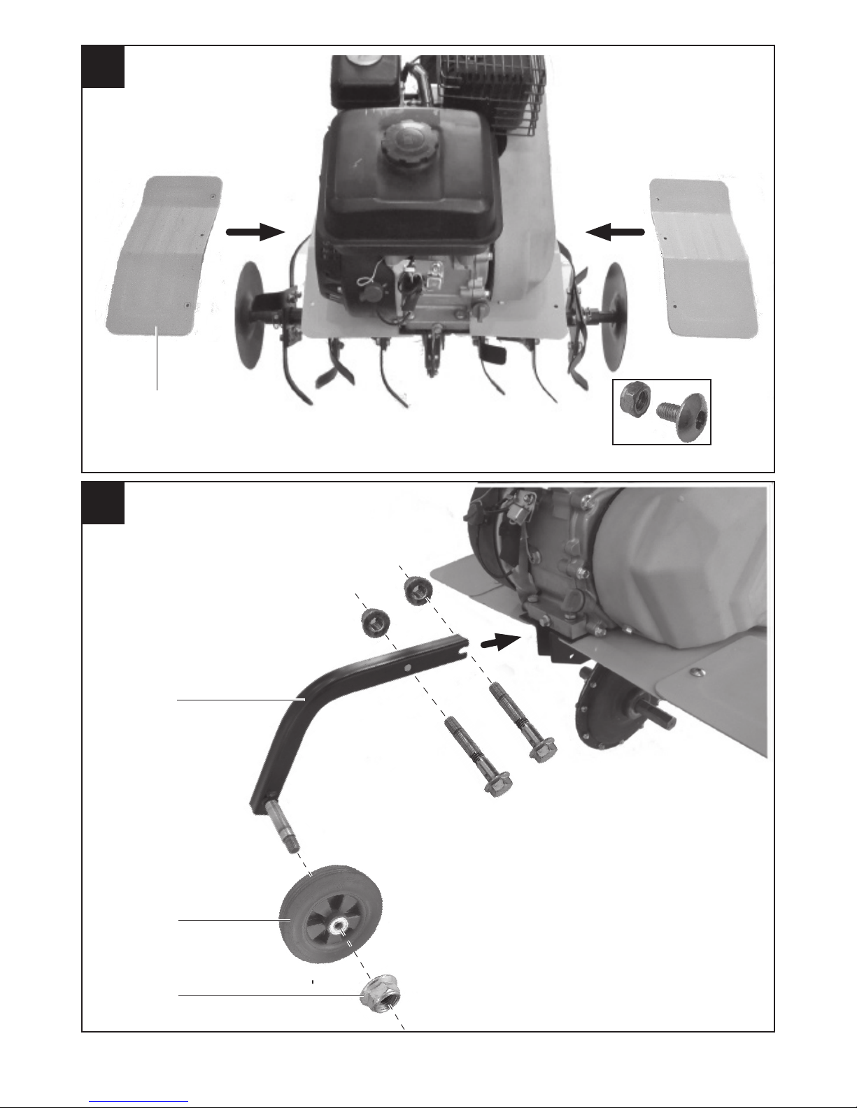
Montaggio protezioni (Fig.D)
- Montare le protezioni (1) facendo combaciare i fori per il fissaggio
e utilizzando le viti e i dadi in dotazione.
Montaggio e regolazione ruota di trasporto (Fig.E)
- Montare la ruota (1) nel supporto (2) e fissare il dado (3).
- Inserire il supporto ruota nel telaio.
- Scegliere l’altezza desiderata della ruota facendo corrispondere il
foro e l’asola del supporto con i fori del telaio.
- Fissare con viti e dadi in dotazione.
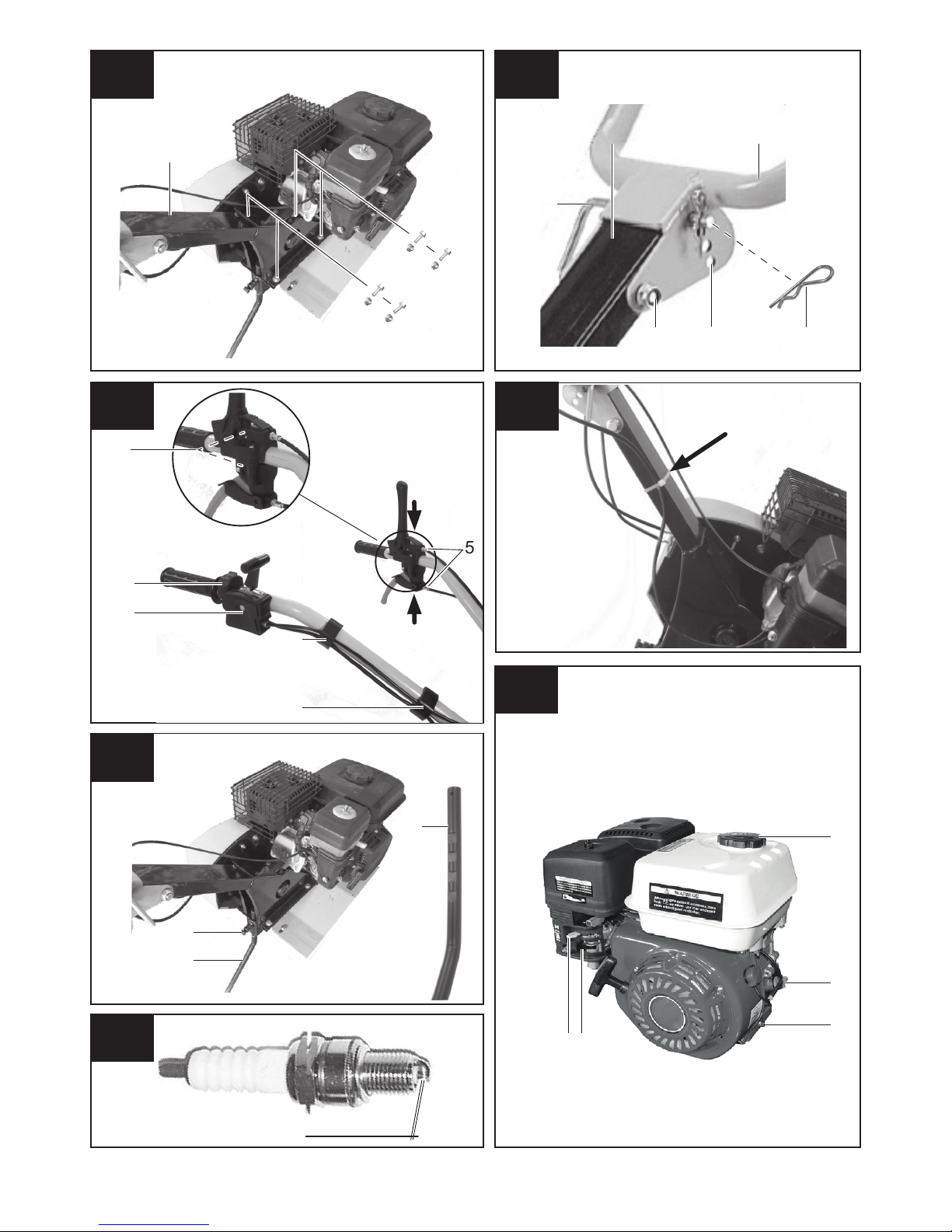
Montaggio supporto manico (Fig. Fa)
- Fissare al corpo della motozappa la piastra di supporto con le quattro
viti e i quattro dadi in dotazione.
Montaggio e regolazione manico (Fig. Fb)
- Inserire il manico (2) nel supporto (1).
- Fissare il manico (2) alla piastra di supporto (1) tramite la vite e il
dado (6) in dotazione.
- Posizionare la leva all’altezza desiderata facendo combaciare uno
dei fori (5) per l’inserimento del perno (4). Fermate il perno con
l’apposita copiglia (3).
Montaggio comandi (Fig. G)
- Montare la leva acceleratore (1) e fissarla nell’apposito foro sul
manico destro tramite la vite e il dado in dotazione.
- Montare il comando ON/OFF (2) e fissarlo sul manico destro tra la
manopola e la leva acceleratore (1) tramite le viti in dotazione.
- Montare le leve di marcia (3) sul manico sinistro unendole e utilizzando le apposite viti per fissarle.
- Fermare i cavi lungo i manici tramite le clips (4) e fissare il cavo del
comando ON/OFF (2) con la fascetta in dotazione lungo il supporto
del manico (Fig. Gb).
ATTENZIONE! Con le leve rilasciate non deve esserci trazione sull’utensile di lavoro. Se necessario regolare i tendicavo (5) in modo da
non avere nessun movimento dell’utensile a leve rilasciate.
Montaggio del timone (Fig. H)
- Inserite il timone (1) nell’apposita sede del telaio.
- Bloccate il timone fissando la vite (2) in corrispondenza di una delle
scanalature presenti sul timone.
DESCRIZIONE COMANDI E REGOLAZIONI
Comando acceleratore (Fig. A pos.16)
- Questo dispositivo permette di variare il numero di giri del motore.
Leva di marcia avanti (Fig. A pos.2)
- Premere lo sblocco e abbassare lentamente la leva per azionare gli
utensili e iniziare il lavoro.
- Rilasciare la leva per arrestare il movimento degli utensili.
Attenzione: La rotazione dell’utensile di lavoro provoca l’avanzamento della motozappa.
- E’ consigliabile effettuare il lavoro in più passate, in questo modo si
otterrà un terreno lavorato senza sovraccaricare la macchina.
Prestare sempre la massima attenzione nei cambi di direzione.
Leva di retromarcia(Fig. A pos.3)
- Premere lo sblocco e tirare lentamente la leva per azionare gli utensili
e iniziare lo spostamento in retromarcia.
- Rilasciare la leva per arrestare il movimento degli utensili.
ATTENZIONE: La macchina deve essere spostata principalmente
dalla forza dell’operatore.Il solo azionamento della leva di retromarcia non è sufficente a muovere la motozzappa. Non utilizzare la
retromarcia per fresare. La retromarcia è da utilizzarsi esclusivamente per fare manovra. Prestate sempre la massima attenzione
nei cambi di direzione.
Ruota (Fig. E)
- E’ possibile regolare la posizione della ruota.
- Per il trasporto della macchina abbassate completamente la ruota.
- Per il lavoro sul terreno, sollevate la ruota bloccandola nella posizione
che rende la macchina più stabile e confortevole all’uso.
Page 8
- 8 -
Timone (Fig. H)
- Il timone ha due funzioni: regola la profondità di zappatura e aiuta
l’operatore a controllare la direzione e la velocità di avanzamento della
motozzappa. Per variare la profondità del timone, fatelo scorrere e
fissatelo nella scanalatura desiderata.
- Abbassando il timone la motozappa rallenta e la zappatura è più profonda.
- Sollevando il timone la motozappa è più veloce e la zappatura è più
superficiale.
AVVIAMENTO E ARRESTO
ATTENZIONE! LA MACCHINA NUOVA DI FABBRICA NON CONTIENE
OLIO NEL MOTORE. PRIMA DI METTERE IN MOTO IL MOTORE E’
NECESSARIO EFFETTUARE IL RIEMPIMENTO.
MOTORE A SCOPPIO (Fig. I)
ATTENZIONE! Ogni operazione indicata di seguito deve essere
effettuata con il motore spento.
- Utilizzare un olio per motore 4T di qualità e altamente detergente,
classificato API categorie SG, SF.
- Un olio SAE 10W-40 è indicato per tutte le temperature di utilizzo,
ma è sempre bene scegliere il tipo di olio in base alla tabella ed alle
temperature medie della zona.
Indicazioni sul tipo di olio da usare:
Temperatura di impiego Grado di viscosità dell’olio
Da -10°C a 0°C SAE 10W o 10W-30, 10W-40
Da 0°C a 25°C SAE 20W o 10W-30, 10W-40
Da 25°C a 35°C SAE 30W o 10W-30, 10W-40
Oltre 35°C e fino a 45°C SAE 40W
Primo utilizzo, riempimento olio motore (Fig I)
- Mettere la macchina su una superficie piana e orizzontale.
- Svitare il tappo di rabbocco olio (1) in senso antiorario.
- Immettere la quantità necessaria di olio di qualità (capacità massima
600 ml).
- Controllare il livello dell’olio ed eventualmente rabboccare: il livello
dell’olio motore non deve superare la parte corrugata posta all’estremità dell’asta di livello.
NB: Per controllare il livello olio, avvitare completamente l’asta di livello
e poi svitare.
- Riavvitare il tappo di rabbocco.
Controllo e rabbocco olio motore (Fig. I)
- Mettere la macchina su una superficie piana e orizzontale.
- Svitare il tappo di rabbocco olio (1) in senso antiorario.
- Pulire l’asta di livello.
- Controllare il livello dell’olio ed eventualmente rabboccare. L’olio deve
lambire l’asta di livello nella sua parte corrugata, posta all’estremità.
NB: Per controllare il livello olio, avvitare completamente l’asta di
livello e poi svitare.
- Riavvitare il tappo di rabbocco.
Sostituzione olio motore (Fig. I)
- Mettere la macchina su una superficie piana e orizzontale.
- Svitare il tappo di rabbocco olio (1) in senso antiorario.
- Mettere un raccoglitore per l’olio sotto il motore in corrispondenza
del tappo scarico olio (2).
- Svitare il tappo olio (2) e toglierlo assieme alla guarnizione.
- Lasciare colare tutto l’olio.
- Chiudere il tappo (2) avendo l’accortezza di riposizionare la guarnizione.
- Ripetere le operazioni previste al paragrafo “Primo utilizzo, riempimento olio motore”.
Rifornimento carburante (Fig. I)
- Il motore della macchina è fornito senza carburante: effettuare il
rifornimento nel serbatoio prima di avviare la macchina.
- Deve essere utilizzata benzina per automobili senza piombo (benzina
verde o Eurosuper).
ATTENZIONE! Non utilizzare mai miscele olio benzina, carburante
sporco o molto vecchio.
- Fate attenzione a non lasciare penetrare nel serbatoio acqua o sporcizia.
- Non utilizzare benzine contenenti alcool.
- Non superare il livello massimo di riempimento.
ATTENZIONE! Pericolo di incendio ed esplosione.
- Effettuare il rifornimento di carburante a macchina spenta. Se il carburante è stato versato sulla macchina o sul pavimento, asciugarlo
prima di avviare la macchina.
- Aprire il tappo serbatoio (3) ruotandolo in senso antiorario.
- Riempire il serbatoio fino ad un massimo di 3 cm sotto il tappo.
- Chiudere il tappo serbatoio ruotando in senso orario.
AVVIAMENTO E ARRESTO
- Eseguire i rifornimenti olio motore e benzina (vedere i rispettivi
paragrafi precedenti).
- Posizionare l’interruttore ON/OFF (Fig. A pos.18) in ON
- Posizionare il rubinetto benzina in ON (Fig. I pos.4).
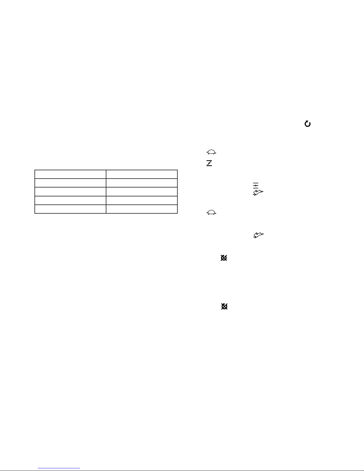
Avviamento a motore freddo
- Posizionate il comando gas (Fig. A pos.16) in corrispondenza del
simbolo .
- Posizionate la leva di starter (Fig. I pos.5) in corrispondenza del
simbolo .
- Tirate energicamente la maniglia di avviamento (Fig. A pos.9), ripetere
l’operazione sino ad avviamento avvenuto.
- Dopo qualche secondo, posizionate la leva di starter (Fig. I pos.5)
in corrispondenza del simbolo e il comando gas (Fig. A pos.16)
in corrispondenza del simbolo
Avviamento con motore caldo
- Posizionate il comando gas (Fig. A pos.16) in corrispondenza del
simbolo
- Tirate energicamente la maniglia di avviamento (Fig. A pos.9), ripetere
l’operazione sino ad avviemento avvenuto.
- Dopo qualche secondo, posizionate il comando gas (Fig. A pos.16)
in corrispondenza del simbolo
Arresto
- Per arrestare la macchina, posizionate l’interruttore ON/OFF (Fig. A
pos.18) in OFF .
PRESCRIZIONI D’USO
ATTENZIONE! La rotazione dell’utensile di lavoro può provocare
gravi lesioni.
- Osservare attentamente le prescrizioni di sicurezza.
- In caso di pericolo rilasciare immediatamente le leve di comando
(Fig. A pos.2 e 3) e spegnere il motore tramite l’interruttore ON/OFF
(Fig. A pos.18) .
- Per il lavoro sul terreno, sollevare la ruota.
- A motore avviato, appoggiare gli utensili da lavoro sul terreno e,
tenendo saldamente la motozappa, infilare il timone nel terreno.
- Azionare la leva di comando avanti (Fig. A pos.2) degli utensili per
far penetrare la fresa sul terreno.
- Sollevando leggermente la fresa mediante i manici, la motozappa si
muove in avanti.
- Il braccio del timone durante il lavoro deve rimanere sempre infilato
nel terreno.
- La macchina risulta adatta a lavorazioni di terreni leggeri o di media
pesantezza, fresatura, sminuzzamento, dissodamento, eliminazione
di erbe infestanti, incorporamento di compost fertilizzanti ecc.
- La macchina non è adatta a terreni ricoperti da cotica erbosa compatta o a terreni pietrosi.
MANUTENZIONE E PULIZIA
ATTENZIONE! Per ogni operazione di controllo o di manutenzione,
assicurateVi che il motore sia spento, l’utensile di lavoro sia fermo
ed il cappuccio della candela scollegato; inoltre svuotare il erbatoio
del carburante. Usate guanti di protezione.
Sostituzione olio motore
- Controllare giornalmente il livello dell’olio e, se necessario, rabboccare.
- Sostituire l’olio, dopo il primo mese o le prime 20 ore di funziona-
Page 9

- 9 -
mento. Successivamente ogni 6 mesi o 80 ore di utilizzo.
- Vedere capitoli precedenti.
Candela accensione
- Controllare ogni 3 mesi o 50 ore di funzionamento ed, eventualmente,
sostituire.
- Per il tipo di candela, vedere i dati tecnici.
- Esaminare la candela e nel caso fossero presenti residui carboniosi,
eliminarli con una spazzola metallica. Se l’elettrodo fosse eccessivamente usurato o l’isolamento danneggiato, sostituire la candela.
- Misurate la distanza tra gli elettrodi: deve essere compresa tra 0,7
e 0,8 mm (Fig. L).
- Fissare tramite apposita chiave per circa ¼ di giro con candela usata,
o per circa ½ giro con candela nuova.
Filtro aria (Fig. A pos.11)
- Pulire ogni 3 mesi o 50 ore di funzionamento, eventualmente sostituire.
- Togliere il coperchio.
- Togliere il filtro.
- Sbatterlo delicatamente su una superficie piana.
- Riposizionare il filtro nella sua sede.-
- Rimettere al suo posto il coperchio della cassetta e avvitare il galletto.
Tubazioni del carburante
- Verificare giornalmente che non ci siano screpolature nel tubo di
alimentazione e che le giunture siano solide.
- Verificare che non ci siano perdite di carburante.
- Sostituire se necessario.
Pulizia della macchina e delle frese
- Una regolare cura della macchina ne garantisce una perfetta efficienza
ed una lunga durata.
- Pulite la macchina con una spazzola morbida o un panno.
- Non usate mai getti d’acqua o solventi per togliere lo sporco perché
potrebbero danneggiarsi alcuni componenti.
- L’organo maggiormente sottoposto ad usura è l’utensile di lavoro;
controllate ogni volta che non ci siano deformazioni o usure eccessive
sulle lame.
- Dopo ogni giornata di utilizzo togliete tutti i residui di terriccio dalle
frese, smontatele e applicate uno leggero strato di grasso sull’albero
di supporto delle frese.
- Per prevenire la formazione di ruggine, applicate sulle frese una
piccola quantità di olio o lubrificante al silicone prima del rimessaggio
per lunghi periodi.
RICERCA GUASTI
Il motore non parte
- L’interruttore (Fig. A pos.18) è in posizione OFF . Vedere capitolo
“avviamento e arresto”.
- Non c’è benzina nel serbatoio: metterla.
- Il rubinetto della benzina (Fig.I pos.4)è chiuso: aprirlo.
- Le tubazioni della benzina sono intasate: pulirle.
- La candela non fa scintille, è sporca o usurata: pulirla o sostituirla.
- La candela nuova non fa scintille: rivolgersi ad un centro assistenza
autorizzato.
- Altro: rivolgersi ad un centro assistenza autorizzato.
Il motore parte e poi si spegne
- Il rubinetto della benzina (Fig.I pos.4) è chiuso: aprirlo.
- Sporco nell’impianto di alimentazione del carburante: pulire.
- Il filtro dell’aria è sporco: pulirlo.
- Eseguire il rifornimento di carburante.
- Altro: rivolgersi ad un centro assistenza autorizzato.
Il motore si ferma
- Ridurre il carico sull’utensile.
- Limitare la profondità di lavoro tramite il timone.
- Eseguire il rifornimento di carburante.
- Lasciare raffreddare il motore se surriscaldato e successivamente
riavviatelo.
- Altro: rivolgersi ad un centro assistenza autorizzato.
L’utensile di lavoro non gira o non ha coppia
- La leva di comando non è azionata.
- Ridurre il carico sull’utensile.
- È da registrare la maniglia di avviamento delle frese. Rivolgersi ad
un centro di assistenza autorizzato.
- La cinghia di trasmissione è da sostituire. Rivolgersi ad un centro di
assistenza autorizzato.
- Altro: rivolgersi ad un centro assistenza autorizzato.
IMMAGAZZINAMENTO
ATTENZIONE! Superfici calde. Alcune parti rimangono a temperature elevate anche per alcune ore dopo l’arresto della macchina; attendete il raffreddamento completo prima dell’immagazzinamento.
- Dopo ogni utilizzo, effettuate una accurata pulizia di tutta la macchina
e sue parti accessorie (vedi paragrafo manutenzione), eviterete così
l’insorgere di eventuali muffe.
ATTENZIONE! Assicurarsi che l’ambiente non sia umido e/o polveroso.
- Togliere tutto il carburante dal serbatoio.
- Vuotare la vaschetta del carburatore tramite la vite di scarico sul
fondo della stessa.
- Sostituire l’olio motore.
- Versare qualche goccia di olio motore nel foro della candela e mettere
il motore in posizione di compressione.
- Riponete la macchina lontano dalla por tata dei bambini, in posizione
stabile e sicura e in luogo asciutto, temperato e libero da polveri.
- Proteggete la macchina dalla luce diretta, tenetela possibilmente al
buio o in penombra.
- Non chiudete la macchina in sacchi di plastica, potrebbe formarsi
dell’umidità.
- Finita la stagione di utilizzo la macchina deve essere sottoposta una
accurata pulizia e verifica dell’efficienza dei suoi componenti.
DEMOLIZIONE
Per la salvaguardia dell’ambiente procedete secondo le norme vigenti
del luogo.
ATTENZIONE! Prima di demolire la macchina, scaricate completamente il serbatoio carburante, scaricate l’olio motore consegnandolo ad un centro raccolta olio usato.
Non gettate l’imballo nei rifiuti ma portatelo ad un centro di raccolta
per il riciclaggio.
Quando la macchina non è più utilizzabile ne riparabile, procedete allo
smontaggio delle parti per lo smaltimento differenziato dei rifiuti. Tutti
i componenti plastici riportano una sigla identificatrice del materiale
di cui sono composti: questa servirà in futuro
per il riciclaggio dello stesso.
GARANZIA
Il prodotto è tutelato a norma di legge contro non conformità rispetto
alle caratteristiche dichiarate purché sia stato utilizzato esclusivamente
nel modo descritto dalle istruzioni, non sia stato manomesso in alcun
modo, sia stato conservato correttamente, sia stato riparato da tecnici
autorizzati e, ove previsto, siano stati utilizzati solo ricambi originali.
In caso di utilizzo industriale o professionale oppure in caso di impiego
simile la garanzia ha validità di 12 mesi.
Per emettere una richiesta di intervento in garanzia è necessario
presentare la prova di acquisto al rivenditore o ad centro assistenza
autorizzato.
Page 10

- 10 -
10 Important! The engine gives off a poisonous, odourless and
colourless gas: inhalation may cause nausea, fainting and death.
Keep a safe distance.
11 Noise level
12 Engine emissions marking
13 Do not smoke or use naked flames
14 Do not remove or tamper with the machine safety or protection
devices.
15 Use ear plugs and protective goggles.
16 Wear protective gloves and footwear.
17 Caution: Flammable
SAFETY REGULATIONS
Training
- Carefully read the instructions. Become familiar with the controls
and the correct use of the machine.
- Never allow children or people who are not familiar with these in-
structions to use the machine.
- Local regulations may fix a minimum age for using this machine.
- Never work when people, in particular children, or pets are nearby.
- Don’t forget that the operator or the person using the machine is
responsible for accidents or danger to other people or their property.
Preparation
- Do not use the machine if you are tired or under the effects of alcohol
or drugs.
- Whilst working, always wear protective shoes and long trousers. Do
not use the machine with bare feet or wearing sandals.
- Always carefully inspect the area where the machine will be used
and remove any objects that could be thrown up by the machine.
WARNING! Petrol is highly inflammable.
- Keep fuel in the appropriate resistant containers;
- Only refuel outside and do not smoke during this operation;
- Add fuel before starting the engine. Never remove the fuel tank cap
or add petrol when the engine is working or when it is hot;
- In case of petrol leaks, do not try to start the engine, but move
the machine away from the area where the petrol leaked and avoid
creating sparks in that area until the petrol vapour has evaporated.
- Always put the fuel tank and the petrol container caps back on
correctly;
- Replace defective silencers.
- Before use, always visually check to make sure that the blades are
not damaged or worn.
Replace the whole set of blades if any are worn or damaged, to keep
the balance.
Use
Do not use the engine indoors as poisonous carbon monoxide gases
can be emitted.
Only work the soil in daylight or in a good source of artificial light.
Always check that there are stable support points on slopes.
Always walk with the machine – never run.
Always be very careful when changing direction and in particular on
slopes.
Never work on extremely steep slopes.
Be extremely careful when pulling the machine towards you.
Do not modify the calibration of the engine’s rotation speed regulator.
Do not overload the engine.
Never load the machine up with additional weight.
Do not drag the motor hoe along hard surfaces or along uneven
surfaces such as steps.
Start the engine carefully following the instructions and keeping your
feet well away from the tools;
Do not put your hands or feet near to the rotating parts;
Never lift or transport the machine when the engine is working;
Always move the motor hoe using both hands;
Stop the engine:
- Every time you move away from the machine.
- Before refuelling;
- Before maintenance or cleaning;
Reduce the engine speed when switching off the engine and close the
fuel cock when you have finished working.
g
Congratulations on your excellent choice. Your new tool has been
manufactured according to the highest quality standards, guaranteeing
you long term service and safety.
USER INSTRUCTIONS
WARNING! Before using the machine, in order to ensure that
handling, initial start-up, starting, use and maintenance are carried
out properly, read
the instructions below that refer to the drawings and technical
data and apply them carefully. Before starting work you should be
familiar with the controls and the correct use of this machine. Make
sure you know how to stop it in case of emergency. The incorrect
use of the machine could result in serious injuries or death and
damage to property. Always consider your safety and the safety of
others and act accordingly.
These instructions and the enclosed documentation are an integral
part of the machine and must accompany it in the case of repair or
resale. Carefully keep the documentation supplied with the machine
tool close at hand for consultation in case of need. The attached
sheet contains the machine’s pictures, technical data and warranty.
The documentation does not include a list of spare parts since the
authorised assistance centres already have one.
WARNING! The motor hoe is a product for non-professional use,
exclusively for breaking up clods and turning over the ground of
small and medium-sized surfaces in private gardens.
Any use other than that indicated in these instructions may damage
the machine and constitute a serious risk to both people and property.
The descriptions and illustrations are not intended to be strictly binding.
The company reserves the right to make changes at any times, without
having to update this manual.
MACHINE DESCRIPTION (FIG. A)
1 Handlebar
2 Work tool forward control lever.
3 Reverse lever.
4 Handlebar adjustment plug.
5 Screw for fixing drawbar.
6 Fuel tank cap
7 Oil refuel / level rod
8 Oil cap.
9 Engine
10 Air filter
11 Carburettor.
12 Work tool.
13 Wheel for transporting machine when reclined.
14 Spark plug cap and spark plug.
15 Gas control lever.
16 Reduction unit, transmission shaft.
17 The reduction gear unit, transmission shaft.
18 On/Off control.
19 Side disc.
DESCRIPTION OF MARKS AND SYMBOLS (FIG. B)
1 Machine mark and model.
2 Technical data
3 Batch number.
4 Mark of Conformity.
5 Important! Read the instructions carefully before use.
6 Important! Danger – rotating parts, keep hands and feet far from
the working area whilst the engine is working.
7 Important! Risk of stone splash: keep the safety distances.
8 Important! Switch the engine off and disconnect the spark plug
cap before making any adjustments or carrying out maintenance
or cleaning operations.
9 Important! Danger of hot surfaces. Some of the outer surfaces
on the machine can reach high temperatures. Some surfaces can
remain hot after the engine is turned off. Keep a safe distance.
Page 11

- 11 -
Maintenance and storage
- If maintenance is carried out on the machine, switch off the engine
and take off the spark plug cap. Pay attention to the hot parts of the
machine like parts of the engine and transmission shaft.
- Always use gloves.
- Keep all nuts, bolts and screws tight to guarantee safe use of the
machine.
- Never put the machine away with petrol in the tank in a closed
building where there could be naked flames or sparks.
- Let the engine cool down before storing the machine in any closed
environments.
In order to reduce the risk of fire, keep the engine, the silencer and
the petrol storage area free from grass, leaves, inflammable materials
or excessive grease.
- For safety reasons, replace worn or damaged parts;
- If the fuel tank needs to be emptied, empty it outside.
STARTING UP
The machine may be supplied with some loose components. For their
assembly, observe the following instructions.
To use the machine correctly and safely it is necessary to assemble
all the components and follow the instructions carefully.
Important! During these operations always wear gloves as the metal
components may have sharp edges.
Assembly of work tools (Fig. C)
- Assemble the tools with the screws and nuts supplied (Fig. Ca).
- Assemble the tools and the disc making the holes line up and
assemble the spring pins (Fig. Cb). The spring of the pins (2) must
be closed respecting the rotation direction of the tools (Fig. Cc).
- Insert the tools (Fig. Cc pos.1) on the reducer shaft (Fig. C pos. 3)
and line up the hole on the shaft (3) with the hole in the tools and
assemble the spring pins (2). The spring of the pins (2) must be
closed respecting the rotation direction of the tool (Fig. Cc).
- The work tool spool must be wound in the rotation direction.
Assembling the safety devices (Fig. D)
- Assemble the safety devices (1) making the fixing holes line up and
using the screws and nuts supplied.
Assembly and adjustment of transport wheel (Fig. E).
- Assemble the wheel (1) in the support (2) and fix the nut (3).
- Insert the wheel support in the frame.
- Choose the desired height of the wheel making the hole and the slot
in the support line up with the holes in the frame.
- Fix with the screws and nuts supplied.
Assembly of handle support (Fig. Fa)
- Fix the support plate to the body of the motor hoe with the four
screws and four nuts supplied.
Assembly and adjustment of handle (Fig. Fb)
- Insert the handle (2) in the support (1).
- Fix the handle (2) to the support plate (1) using the screw and nut
(6) supplied.
- Position the lever at the desired height making one of the holes (5)
line up for inserting the pin (4). Fix the pin with the relevant split
pin (3).
Control assembly (Fig. G)
- Assemble the accelerator lever (1) and fix it into the relevant hole
on the right handle using the screw and nut supplied.
- Assemble the ON/OFF control (2) and fix it onto the right handle
between the knob and the accelerator lever (1) using the screws
supplied.
- Assemble the movement levers (3) on the left handle joining them
and using the relevant screws to fix them in place.
- Fix the cables along the handles using the clips (4) and fix the
ON/OFF control cable (2) with the band supplied along the handle
support (Fig. Gb).
IMPORTANT! With the levers released, there should be no traction
on the work tool. If necessary adjust the cable tensioners (5) so that
there is no movement of the tool with the levers released.
Assembly of the drawbar (Fig. H)
- Insert the drawbar (1) in the relevant housing on the frame.
- Lock the drawbar by fixing the screw (2) into one of the grooves
provided on the drawbar.
DESCRIPTION OF CONTROLS AND ADJUSTMENTS
Accelerator control (Fig. A pos.16)
- This device allows the number of engine revolutions to be
changed.
Forward movement lever (Fig. A pos.2)
- Press the release button and slowly lower the lever to activate the
tools and start work.
- Release the lever to stop the tool movement.
Important: The rotation of the work tool causes the motor hoe to
move.
- It is advisable to carry out the work in more than one stint, so that
the soil will be properly worked without overloading the machine.
Always be very careful when changing direction.
Reverse lever (Fig. A pos.3)
- Press the release button and slowly pull the lever to activate the
tools and start the reverse movement.
- Release the lever to stop the tool movement.
WARNING: The machine must be moved mainly by the operator’s
strength. Moving the reverse lever is not sufficient to move the motor hoe. Do not use reverse for milling. Reverse must only be used
for manoeuvring. Always be very careful when changing direction.
Wheel (Fig. E)
- The position of the wheel can be adjusted.
- For transporting the machine fully lower the wheel.
- For working on the ground, lift the wheel locking it in the position
which makes the machine more stable and comfortable to use.
Drawbar (Fig. H)
- The drawbar has two functions: it adjusts the digging depth and
helps the operator control the direction and speed of the motor hoe.
To change the depth of the drawbar, slide it and fix it into the desired
groove.
- Lower the drawbar to slow down the motor hoe and dig more deeply.
- Lift the drawbar to speed up the motor hoe and dig less deeply.
STARTING AND STOPPING
WARNING! WHEN THE MACHINE IS BRAND NEW IT DOES NOT
HAVE OIL IN THE ENGINE. BEFORE STARTING-UP THE ENGINE, IT
NEEDS TO BE FILLED UP.
INTERNAL COMBUSTION ENGINE (FIG. I)
WARNING! All the operations described below must be carried out
with the engine switched off.
Use a quality, highly detergent oil for 4T engines, classified under
API categories SG or SF.
An SAE 10W-40 oil is suitable for all working temperatures, but it
is always best to choose the oil type on the basis of the table and
average temperatures of the area.
Information on the oil to be used:
Temperature for use Degree of oil viscosity
From -10°C to 0°C SAE 10W or 10W-30, 10W-40
From 0°C to 25°C SAE 20W or 10W-30, 10W-40
From 25°C to 35°C SAE 30W or 10W-30, 10W-40
From 35°C to 45°C SAE 40W
First use, filling up the engine oil (Fig I)
- Position the machine on a flat, horizontal surface.
- Unscrew the oil cap 1 in an anti-clockwise direction.
- Fill with the required quantity of quality oil (maximum capacity 600
ml).
Page 12

- 12 -
- Check the oil level and top up if necessary: The engine oil level
must not go past the corrugated part at the end of the level rod.
N.B.: To check the oil level, screw in the level rod completely and
then unscrew.
- Screw the oil cap back on.
Checking and topping up the engine oil (Fig. I)
- Position the machine on a flat, horizontal surface.
- Unscrew the oil cap (1) in an anti-clockwise direction.
- Clean the level rod.
- Check the oil level and top up if necessary. The oil must
touch the level rod on the corrugated part at the end.
N.B. To check the oil level, screw in the level rod completely and
then unscrew.
- Screw the oil cap back on.
Replacing the motor oil (Fig. I)
- Position the machine on a flat, horizontal surface.
- Unscrew the oil cap (1) in an anti-clockwise direction.
- Place an oil drip tray beneath the engine, in line with the oil drain cap
(2).
- Unscrew the oil cap (2) and remove it together with the gasket.
- Let all the oil run out.
- Close the cap (2) making sure that you put the gasket back on.
- Repeat the operations described in the “First use, filling up the engine
oil” section.
Filling up with fuel (Fig. I)
The machine’s engine is supplied without fuel: fill up the tank before
starting the machine!
Unleaded car petrol should be used (green or eurosuper).
WARNING! Never use oil/petrol mix, dirty or very old fuel.
- Do not allow water or dirt to enter the tank.
- Do not use petrol containing alcohol.
- Do not exceed the maximum filling level.
WARNING! Risk of fire and explosion.
Refuel when the machine is switched off. If the fuel has splashed onto
the machine or floor, dry it up before starting the machine.
- Open the tank cap 3, turning it in an anti-clockwise direction.
- Fill the tank up to a maximum of 3 cm beneath the cap.
- Close the tank cap by turning it in a clockwise direction.
STARTING AND STOPPING
- Fill up the engine oil and petrol (see the respective paragraphsabove).
- Position the ON/OFF switch (Fig. A pos.18) to ON
- Position the petrol tap (Fig. I pos.4).
Cold engine start-up
- Position the gas control (Fig. A pos.16) in line with the symbol
- Position the starter lever (Fig. Ipos.5) in line with the symbol .
- Pull the starter handle sharply (Fig. A pos.9) and repeat the operation
until the engine has started.
- After a few seconds, position the starter lever (Fig. I pos.5) in line
with the symbol and the gas control (Fig. A pos.16) in line
with the symbol .
Hot engine start-up
- Position the gas control (Fig. A pos16) in line with the symbol
- Pull the star ter handle sharply (Fig. A pos.9) and repeat the operation
until the engine has started.
- After a few seconds, position the gas control (Fig. A pos.16) in line
with the symbol .
Switching off
- To stop the machine, press the ON/OFF switch (Fig. A pos.18) to
OFF .
SAFETY INDICATIONS
WARNING! The rotation of the work tool can cause serious injuries.
Carefully observe the safety indications.
- In the event of danger immediately release the control levers (Fig. A
pos.2 and 3) and turn off the engine using the ON/OFF switch (fig.
A pos.18) .
- For working on the ground, lift the wheel.
- Once the engine is started, place the work tools (knives) on the
ground and insert the drawbar in the ground holding the motor hoe
firmly.
- Activate the forward control lever (Fig. A pos.2) of the tools to make
the hoe penetrate the ground.
- Lifting the miller slightly with the handles to move the motor hoe
forwards.
- The drawbar arm must always be into the ground during operation.
- The machine is suitable for light or medium weight soil, milling,
chipping, clearing, removing weeds, incorporating compost, fertilisers, etc…
- The machine is not suitable for ground covered with compact turf
or stony soil.
MAINTENANCE AND CLEANING
WARNING! For all control and maintenance operations, make sure
that the engine is switched off, the work tool stationary and the
spark plug cap disconnected. Drain all fuel from the tank. Always
wear protective gloves.
Replacing the engine oil
Check the oil level on a daily basis and top up if necessary.
Replace the oil after the first month or after the first 20 hours of use.
Then replace it every 6 months or after every 80 hours of use.
See the previous chapters.
Spark plug (Fig. L)
Check it every 3 months or after every 50 hours of use, and replace
it if necessary.
- See the technical data in reference to the spark plug type.
- Examine the spark plug and remove any carbon residue with a metal
brush. Replace the spark plug if the electrode is excessively worn or
the insulation is damaged.
- Measure the distance between the electrodes: it should be between
0.7 and 0.8 mm (Fig. L).
- Screw the spark plug back in by hand.
- Secure a used spark plug with around ¼ turn of the spanner, and a
new one with around ½ turn of the spanner.
Air filter (Fig. A pos.11)
Clean it every 3 months or after every 50 hours of use, and replace
it if necessary.
1.Remove the cover (10 fig. A).
2.Remove the filter.
3.Knock it gently on a flat surface.
4.Replace the filter in its housing.
5 Replace the box cover and screw on the wing nut.
Fuel tubes
Make sure that there are no cracks in the fuel pipe and that the joints
are solid on a daily basis.
Check that there are no fuel leaks.
Replace where necessary.
Cleaning the machine and millers:
- Regular machine maintenance will keep it in good working order and
ensure a long working life.
- Clean the machine using a soft brush or cloth.
- Never use jets of water or solvents to remove dirt as they could
damage some components.
The part which is most subject to wear is the work tool; check every
time that there are no deformations or excessive wear on the blades.
After every use, remove all soil residues from the millers, disassemble
them and apply a light layer of grease on the miller support shaft.
To prevent the formation of rust, apply a small quantity of oil or silicone
lubricating oil on the millers before storing the machine for long periods.
TROUBLESHOOTING
The engine does not start:
- The ignition control (Fig. A pos.18) is in the “stop” position . See
chapter “starting and stopping”
- There is no petrol in the tank: fill it up.
- The petrol cock (Fig. L pos.4) is closed (where fitted): open it.
- The petrol pipes are blocked: clean them.
Page 13

- 13 -
- There is dirt or water in the carburettor tray: empty the tray removing
the nut
- The spark plug does not spark, is dirty or worn: clean or replace it.
- The new spark plug does not spark: contact an authorised service
centre.
- Other: contact an authorised service centre.
The engine starts then stops:
- The petrol cock (Fig.L pos.4) bleed valve is blocked: clean it.
- Dirt in the fuel supply system: clean it.
- The air filter is dirty: clean it.
- Fill up with fuel.
- Other: contact an authorised service centre.
The engine stops:
- Reduce the load on the tool.
- Limit the work depth using the drawbar.
- Fill up with fuel.
- Leave the engine to cool down if overheated and then start it up again.
- Other: contact an authorised service centre.
The work tool does not turn or has no torque:
- The control lever is not operating.
- Reduce the load on the tool.
- The miller starting handle needs to be set.
- The transmission belt needs replacing. Contact an authorised service
centre.
- Other: contact an authorised service centre.
STORAGE
WARNING! Hot surfaces. Some parts of the machine may stay hot
for several hours after it has been switched off. Wait for it to cool
down completely before storing it.
- After use, clean the entire machine and its accessories carefully (see
maintenance paragraph), thus preventing any mould from forming.
WARNING! Make sure that the storage environment is not damp
and/or dusty.
1. Remove all the fuel from the tank.
2. Empty the carburettor tray using the drain screw on the bottom of
it (if applicable) or let the machine work until it runs out of petrol in
the carburettor.
3. Replace the engine oil.
4. Pour a few drops of engine oil into the spark plug hole and put the
engine in the compression position.
- Keep the machine out of reach of children, in a stable and safe
position and in a dry place not subject to extreme temperatures and
free from dust.
- Protect the machine from direct sunlight, keeping it in the dark where
possible, or in the shade.
- Do not close the machine in nylon bags as damp could form.
- Once the season is over, the machine should be cleaned thoroughly
and you should ensure that all its components are in good working
order.
DEMOLITION
In order to safeguard the environment, proceed in compliance with
local regulations.
WARNING! Before demolishing the machine, drain the fuel tank
completely and drain the engine oil, handing it over to a used oil
collection centre.
Do not throw the packaging away. Take it to a recycling centre instead.
When the machine is no longer usable or reparable, dismantle the
various parts for differentiated refuse collection. All the plastic components bear an acronym identifying the materials they are made from.
this will be useful in the future
for recycling.
WARRANTY
The product is protected by law against non-compliance with the declared characteristics provided it is used only in the manner described
in the instructions, it has not been tampered with in any way, it has
been stored properly, has been repaired by authorized and, where
applicable, have been used only original spare parts.
In the case of industrial or professional use or when using such a
guarantee is valid for 12 months.
To issue a claim under warranty you must present proof of purchase
to your dealer or authorized service center.
Page 14

- 14 -
Page 15

- 15 -
Page 16

 Loading...