

Page 1
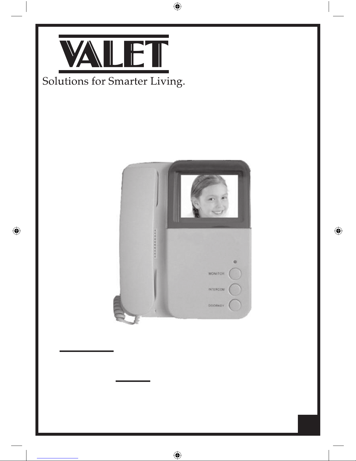
Valet Video Intercom
VBC Plus System
Installation Guide
User Guide
PLEASE READ AND UNDERSTAND THIS MANUAL
BEFORE INSTALLING AND OPERATING
1
Page 2
Contents
2
Video Intercom System
1. Intercom Monitor and Handset 3
2. Doorbell/Camera 4
3. Instalment method and wiring diagrams 5-9
4. Operation Instructions 10
5. Technical Specifi cations 11
6. Notes 12
PAGE
Page 3
VOLUME
DC IN
RING VOLUME
ADJUST
JS-VP
JS-AP
JP-LK
JP-VD
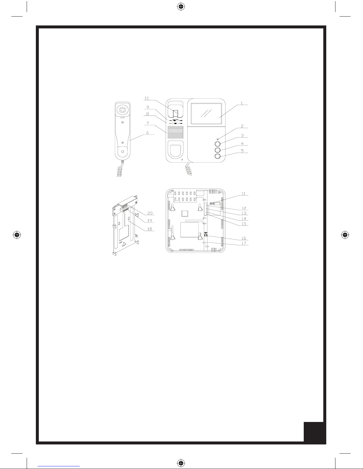
1. INTERCOM MONITOR AND HANDSET
1. Screen
2. Indicator
3. Monitor button
4. Intercom button
5. Door key button
6. Phone Handset
7. Loud speaker
8. Brightness adjustment
9. Contrast adjustment
10. Hang up latch
11. Ringing volume
12. JS-VP port for Back Bracket Board
13. Not Used
14. JP-VD port for image impedance
15. JP-LK port for setting door-release time
16. DC Input
17. Not Used
18. Back Bracket Board
19. JW-VP port for connecting cable
20. Port for Doorbell Camera connection
220mm (h) x 190mm (w) x 55mm (d)
3
Page 4
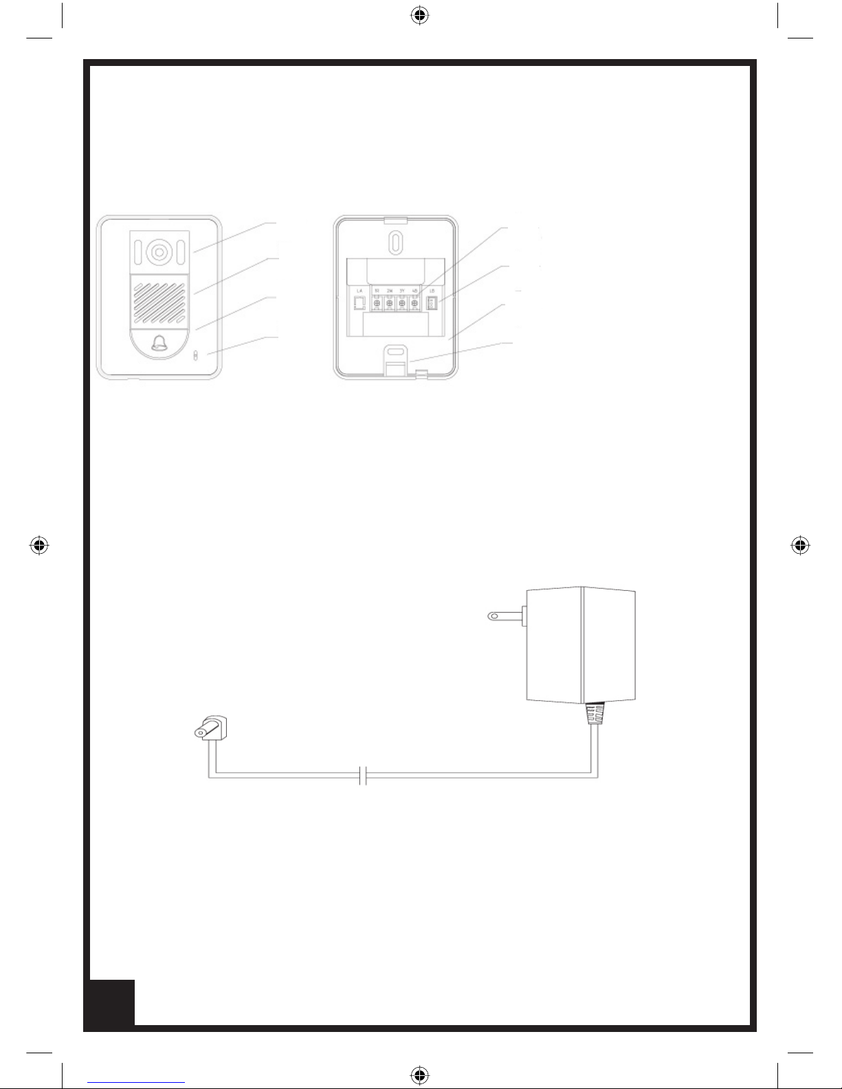
2. DOOR BELL/CAMERA
128(h )x 98(w) x 43(d)
1. Camera
2. Speaker
3. Call button
4. Microphone
5. Connecting Terminal
6. Terminal for door-release
7. Back Board
8. Access Bracket
Instalment screws: M4 5pc Doorbell Camera Bracket
M6 1pc Monitor Mounting Bracket
1
2
3
4
5
6
8
7
4
Power supply adapter
3. ACCESSORIES
Page 5

4. MONITOR / HANDSET INSTALLATION
Note: An expansion module PCB is required to be fi tted to the main
monitor bracket in multiple monitor and/or 2 doorbell camera systems.
Installing method:
1) Check Mounting Height (145cm/160cm).
2) Pass doorbell camera and power adapter cable through the rear of the
mounting bracket before connection.
3) Fix mounting bracket to wall at chosen height.
4) Connect cables to rear of monitor (see page 7).
5) Attach rear of monitor to mounting bracket hooks and press fi rmly
into place.
6) Connect hand set cable to monitor.
5
Page 6

5. DOORBELL/CAMERA INSTALLATION
The Doorbell/Camera position should be tested before fi t off to check
the camera position in regards to height and angle. It is recommended
you make a temporary connection to check your chosen position is a
good all round choice for the average visitor. Ensure the camera is not
facing direct sun and will not be impacted by driving rain or sprinkler
systems. Weather shields and various face plate accessories are
available as optional extras. Please see your Valet Dealer or
call 1800 050 333.
1) Chose height of Camera
2) Separate Doorbell/Camera fascia from Bracket
3) Pass cable through rear of bracket
4) Fix mounting bracket to wall at chosen height
5) Connect cable to rear of Doorbell/Camera
6) Attach Doorbell/Camera to mounting bracket
6
Page 7

6. SINGLE MONITOR
CONNECTING AND DIAGRAM
Valet recommends that Valet 8 Intercom cable is used in the wiring of
its video intercom systems. The Valet 8 cable provides the appropriate
screened cable for both video and audio signals.
Connecting Cable to the Monitor Mounting Bracket PCB
1R: +12V Power supply positive for Door bell/camera
2W: GND Power supply ground for Door bell/camera
3Y: VIDEO Image signal transmitting line
4B: AUDIO Talk and control lines
When the connecting distance between monitor and Doorbell Camera
is over 50m, we suggest using RG-59 (3C-2V) co-axle cable to connect
3Y, 2W connecting terminals.
Connect the supplied 4 colour interface cable to JW-VP on the monitor
mounting bracket PCB. Then connect the other end to JS-VP on the rear
of the monitor (See GX-4P-2C3 below )
Connect the Power Supply Adapter
Note 1: Door Release Timing. The standard setting for Door Release
signal is 1 second. Remove JP-LK jumper to increase time of signal to 3
seconds
Note 2: Please Note: Any Door release fi tted must use its own matched
power supply and connects through LB on the VBC Plus Doorbell
Camera output.
7
Page 8

Multiple Monitor Systems
When adding monitor/handsets a new expansion PCB must be fi tted to your main
monitor mounting bracket. This new PCB allows the single monitor to become a
multiple monitor and Doorbell Camera distributor. The expansion PCB allows up
to 4 monitors and 2 Doorbell Cameras to be connected as a network system. It is
required for multiple monitors and multiple Doorbell Cameras.
Please change only one Monitor mounting bracket PCB with the new expansion
PCB. This determines the Main Monitor setting in the system. All other monitors
become sub monitors (using their existing supplied PCBs)
Multiple Monitor Set Up
In a 2, 3 or 4 monitor system please remove JP-VD jumper in accordance with A or
B cable runs below:
a) If your system is a loop wire set up, ie, The cable from Main Monitor expansion
PCB runs to and through each sub monitor then the last monitor in the loop run
requires JP-VD to remain fi tted, all others are removed.
b) If you have Star Wired cable network eg, each sub monitor has a separate cable
from the main monitor expansion PCB, then any one of the sub monitors can have
the JP-VD fi tted with all others in the system removed.
2 Doorbell Camera System
The expansion PCB is required to be fi tted in 2 Doorbell Camera systems regardless
of the number of monitors. The expansion PCB contains the switching device
between camera images.
7. MULTIPLE MONITOR AND
MULTIPLE DOOR BELL SYSTEMS
8
Page 9

8. MULTIPLE MONITOR SYSTEM
CONNECTION AND NETWORK DIAGRAM
9
Page 10

9. OPERATION
1. When the visitor presses the “CALL” button on the doorbell/camera, the
electronic bell in the monitor/s chime. At the same time, the screen/s display the
visitors’ image.
2. You can pick up the phone from any monitor and talk with the visitor for
90 seconds. If you do not pick up the phone, the images on the screen will
disappear in 30 seconds automatically. In multiple monitor systems, when you
pick up one , the other monitors will turn off automatically.
3. Pressing the monitor button on any monitor at any time allows you to view
outside your door for 30 secs. Press the “MONITOR” button once to view the
image from door 1. If you have a second doorbell/camera installed press the
“MONITOR” button a second time to show the image from door 2. Pressing a
3rd time cancels the image.
4. If your system is connected to a door latch release, you can only use the door
release button function if a visitor has operated the doorbell camera.
5. Remove the handset for access to image contrast and volume controls .
6. When multiple monitors are installed, intercom between two monitors is
available. Any monitor can call its other monitors. Picking up a handset at any
monitor and pressing the “INTERCOM” button calls all the other monitors and
operates their chimes, picking up any other monitor handset opens the intercom
function to talk between those monitors. This function is also available to
transfer a call after answering the doorbell/camera. To transfer a call and image
to another location or person, after answering the doorbell camera, press the
intercom button to alert all other monitors in the system, when a monitor is
answered in another location the originating monitor can hang up.
7. Priority is given to doorbell/camera calls, then intercom, then monitoring.
10
Page 11

10. TECHNICAL SPECIFICATIONS
Monitor/Handset
Display screen 4 inch B/W CRT
Resolution >300 TV lines
Scan frequency 15,625Hz(H) 50Hz(V)
Power voltage DC 15~18V
Video input 75 1Vp-p CCIR standard
Power consumption Standby state 0.5W; working state 15W
Wiring mode 4 wires polar
Dimension 185(W) x 230(H) x 60(D)
Weight 1.20Kg
Doorbell/Camera
Power Source: DC 12V
Camera 1/3 inch CCD/CMOS
Lens F3.6, 72 degree adjustable
Min illumination 0 Lux
Night vision light 6 infrared LED
Power consumption 10w
Dimension 98(W) x 128(H) x 43(D)
Weight 0.2Kg
11
Page 12

NOTES
12
 Loading...