

Page 1

System One
by
HOME
COMMUNICATION
EQUIPMENT
®
OWNERS MANUAL
REV 2
Page 2

TABLE OF CONTENTS
INTRODUCTION…………………………………………..………………………………..2
Features Include
PARTS IDENTIFICATION…………………………………………..……………………..3
POWERING UP THE SYSTEM……………………………………………………..…….3
MODE DEFINITIONS……………………………………………………………………….4
Music Mode
Monitor Mode
Privacy Mode
PAGING CALLS…………………………………………………………………………….6
SELECT CALLS…………………………………………………………………………….7
DOOR/GATE STATION OPERATION……………………………………………………8
AUXILIARY/LOCK OUTPUT………………………………………………………………9
FUNCTIONS OF KEYS AND CONTROLS……………………………………………….9
Local Volume Control
Auxiliary Input Jack – Type B
PROGRAMMING OPTIONS………………………………………………………………10
Program Mode
6 Wire / 8 Wire Mode
Single Digit and Double Digit Select Calling
Keypad Backlighting
Changing Room Station Coding
TROUBLESHOOTING……………………………………………………………………..12
TECHNICAL SPECIFICATIONS………………………………………………………….13
1
Page 3

INTRODUCTION
The SYSTEM ONE Home Communication System provides the simplicity and reliability
of digital technology and can be installed using up to 20 stations offering great flexibility and
convenience.
FEATURES INCLUDE:
Paging and Select call capability so you can target your calls to individual stations, groups or
stations or the entire system
Hands free reply to all calls; especially helpful with young children who can reply from any part of
a room without the need to press a button
Privacy function to avoid being listened to by other stations
Multiple Door/Gate release (Optional)
Automatic reset circuitry so you do not have to remember to reset any switches after making and
intercom call
Switchable keypad back lighting at all room stations
This total Home Communications System continues to set the highest standards
of quality and performance for which Valet® is well known.
To assist in the initial understanding of the operation of this system, we recommend
you follow the order in which the instructions are set out.
System One offers the flexibility of installation without a Master station. For information on
installation of systems with Masters please refer to the Master Supplement.
2
Page 4
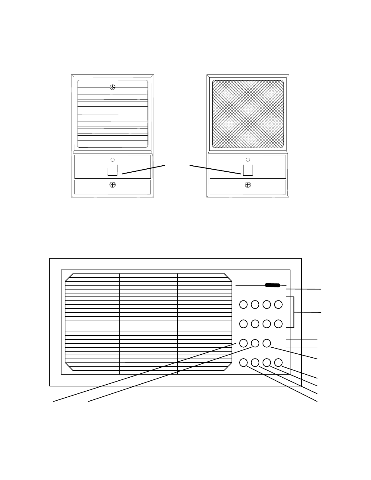
PARTS IDENTIFICATION
Louvered Door Station Decor Door Station
Door Station
21
Room Station
16 23
VOL 0 1 2 3 4 5 6 MAX
1 2 3 4
5 6 7 8
MON MUSPRIV
.
.
CLR HOUSE DOOR AUX
6
20
19
22
24
18
17
1
3
3
Page 5
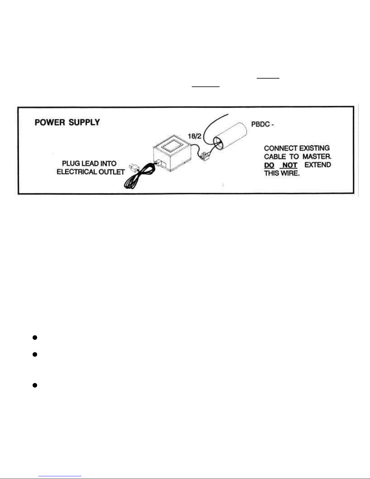
POWERING UP THE SYSTEM
18/2 cable should be connected from the transformer to the DC power booster, this distance should
not exceed 16 feet. The DC power booster unit should be connected directly to the systems most
central room station. Cable for this connection is provided on the DC power booster unit.
MODE DEFINITIONS
System one allows you to choose or alter settings at individual stations. To gain the greatest
benefit from your system, we strongly recommend you carefully read what settings are
available and how you can use them to your advantage.
Music Mode
Any station set to this mode can listen to any other station being monitored, and can
listen to music from the master or auxiliary input jack where these have been fitted.
To select Music Mode:
Press the ‘MUSIC’ key 24 at the station where this function is required
(Red light will come on indicating station is in Music Mode)
Ensure ‘LOCAL VOLUME CONTROL’ 6 is set to a reasonable level
To de-select Music Mode:
Press the ‘MUSIC’ key 24
(Red light will turn off indicating station is no longer in Music Mode)
4
Page 6

Monitor Mode
Any station set to this mode can be listened to by other stations for example;
To ensure that a baby is sleeping soundly or that a sick child or
an elderly parent is comfortable at night.
To select Monitor Mode:
Press the ‘MONITOR’ key 23
(The green light will come on indicating the microphone is activated)
NOTE: Any station desiring to listen to a monitored station should be
set to Music Mode - See above
Listening to monitored stations is more effective if the radio
is turned off at the master **
Any station set to monitor mode will not respond to paging calls,
door calls and door chimes but will respond to select calls which
allows for communication to the station being monitored
To de-select Monitor Mode:
Press the ‘MONITOR’ key 23
The green light will turn off indicating the microphone is de-activated
Privacy Mode
This mode caters for situations where you want to prevent other stations from listening
in to a particular room by disabling the station’s ability to reply to incoming calls.
To engage Privacy Mode:
Press the ‘PRIVACY’ key 16 at the station where this mode of operation
is required
(The green light will flash indicating the station is in Privacy Mode)
To disengage Privacy Mode:
Press the ‘Privacy’ key 16
(The green light will stop flashing indicating the station is no longer in Privacy Mode)
NOTE: - Outgoing calls can be made while in Privacy Mode
- Music, Monitor and Privacy Modes reset on power up and therefore also
reset in the event of a power disruption.
This can be overcome if an optional standby battery is used in conjunction
with the power supply. (Consult your Local Distributor for further information)
5
Page 7

PAGING CALLS
A Paging Call communicates to all other stations with the exception of door stations
and is the best method of speaking to someone if your not exactly sure where they are.
To page all stations:
Press and hold the ‘HOUSE’ key 1 at master or any room station
The green light will turn on indicating your microphone is active
Commence your conversation then release the ‘HOUSE’ key 1 to listen for a reply
The green light will turn off at the station initiating the call and will turn on at all
receiving stations enabling the person(s) receiving the call to reply
* Those replying to a call need not press any buttons. All replies are ‘hands free’
Continue the conversation pressing the ‘HOUSE’ key 1 to talk and releasing the
‘House’ key 1 to listen
When the conversation is complete the system will reset after approximately
20 seconds from when the ‘HOUSE’ key was last released or the system can be
reset manually by pressing the ‘CANCEL / CLEAR’ key 3
Important Exceptions
Stations set to Monitor MODE or with volume control turned to minimum will not
receive Paging calls
Stations set to PRIVACY MODE will not allow a ‘hands free reply’
Do not initiate a call if the red light is flashing as this indicates that someone is
already using the system to communicate
6
Page 8

SELECT CALLS
A Select Call directs communication to a particular station or group of stations within
the system with the exception of door stations.
If your system has been programmed for double digit format to allow for more than eight
Select Call channels, refer to section “Initiating a Select Call – Double Digit Format” below.
Initiating a Select Call - Single Digit Format:
Press and hold the selection number (1-8) on the dialing keypad 20 at the
master or any room station
The green light will turn on indicating your microphone is active
Commence your conversation then release the key to listen for a reply
The green light will turn off at the initiating station and will turn on at the receiving
station(s) enabling the person(s) receiving the call to reply
* Those replying to a call need not press any buttons. All replies are ‘hands free’
Continue the conversation by pressing the selected number to talk and releasing
the selected number to listen
When the conversation is complete the system will reset after approximately
20 seconds from when the selected number was last released or the system
can be reset manually by pressing the ‘CANCEL / CLEAR’ key 3
Initiating a Select Call - Double Digit Format:
Press the first digit of the selection number (1-3) on the dialing keypad 20
at any room station
The red light will begin flashing
Press and hold the second digit of the selection number (1-8) on the dialing keypad
The green light will turn on indicating your microphone is active
Commence your conversation then release the second digit key to listen for a reply
The green light will turn off at the initiating station and will turn on at the receiving
station(s) enabling the person(s) receiving the call to reply
* Those replying to a call need not press any buttons. All replies are ‘hands free’
Continue the conversation by pressing the second digit key to talk and releasing
the second digit key to listen
When the conversation is complete the system will reset after approximately
20 seconds from when the second digit key was last released or the system
can be reset manually by pressing the ‘CANCEL / CLEAR’ key 3
7
Page 9

Important Exceptions
Stations with volume controls turned to minimum will not receive any calls
Stations set to PRIVACY MODE will not allow a ‘hands free reply’
Do not initiate a call if the red light is flashing as this indicates that someone is
already using the system to communicate
DOOR/GATE STATION OPERATION
How to talk to door/gate stations:
A visitor activating the Front Door/Gate Button 21 activates an electronic door chime
that rings at all stations providing local volume controls are not turned to minimum and
the stations are not set to Monitor mode.
To talk to a visitor at the Front Door or Gate
Press and hold the ‘DOOR’ key 17 at the master or at any room station
The green light will come on
Commence the conversation and release the ‘DOOR’ button to listen to reply
The green light turns off
The visitor does not have to press anything.........just talk
Continue the conversation pressing the ‘Door’ key to talk and releasing
the ‘DOOR’ key to listen
When the conversation is complete the system will reset after approximately
20 seconds from when the ‘Door’ key 17 was last released or the system can be
reset manually by pressing the ‘CANCEL / CLEAR’ key 3
Important Exception
Stations set to Monitor MODE or with volume control turned to minimum will not
hear the electronic chime when a visitor presses the Front Door/Gate button 21
8
Page 10

AUXILIARY/LOCK OUTPUT
Electronic door locks, Automatic gates, Courtesy lights, Alarm panic circuits, etc. can
be controlled from the master or any room station if optional auxiliary output boards
have been fitted to your system.
These outputs can be programmed to time out or toggle depending on the application.
To activate an output:
Press and release the ‘AUXILIARY OUTPUT’ key 18 at master or any room
station followed by the predetermined number on the ‘DIALLING KEYPAD’ 20
for the device you wish to control
If the output is programmed to time out the device will de-activate or reset after a
predetermined period of time
If the output is programmed to toggle the output will remain on until the
‘AUXILIARY OUTPUT’ key 18 followed the predetermined number on the
‘DIALLING KEYPAD’ 20 are pressed again
NOTE: For this Optional feature to be available the fitting of Auxiliary output boards
and additional wiring are required at installation.
FUNCTIONS OF KEYS AND CONTROLS
Local Volume Controls 6
Adjustment of this control will set the speaker volume at the particular station for:
a) Music
b) Communication
c) Electronic Chime
Slide the control to the desired level
(Usual setting is about 3/4)
Auxiliary Input Jack - Type B
Optional accessory allowing an external audio device to be connected to the
intercom system where a master has not been incorporated.
Note: A suitable connecting lead is required to connect the external audio device
to either of the input jacks above.
9
Page 11

PROGRAMMING OPTIONS (System One w/VR102 Board Only)
In Program mode System One room stations can have the following options programmed:
6 Wire or 8 Wire operation (Installer option)
Single digit or double digit operation for Select Calls (Installer option)
Keypad back lighting - on or off (User option)
Station coding (User option)
Enter Program mode
Enter programming mode by pressing the “PRIVACY” and “MONITOR” buttons simultaneously.
6 Wire / 8 Wire Mode
This setting is determined by how the system has been wired.
Green LED off indicates 6 Wire and Green LED on indicates 8 Wire
Pressing house button toggles between 6 Wire and 8 wire modes
NOTE: This setting is usually set by the installer and should not be altered.
Single digit and Double digit Select Calling
Single digit Select Calling is designed for systems requiring up to 8 select call channels.
Double digit Select Calling is designed for systems requiring from 9 to 20 select call channels.
Single digit numbers are displayed as a series of 1 to 8 repeated flashes
Double digit numbers are displayed by 2 quick flashes (indicating Double digit mode)
followed by 1 to 3 flashes (indicating the first digit) followed by 1 to 8 flashes
(indicating the second digit)
The Auxiliary button is used to toggle between Single Digit & Double Digit modes
NOTE: This setting is usually set by the installer and generally should not be altered.
Keypad Backlighting
Keypad illumination can be toggled on or off using the Door button.
10
Page 12

Changing Room Station Coding
For the purpose of Select Calling (Calling individual or grouped stations) each station must be
allocated a number between 1 and 8 (Single digit) or 11 and 38 (Double digit). If more than one
station is allocated the same number, the stations having the same number will form a group.
Allocating a number to a station, is done by means of programming via the keypad.
Single Digit
Enter a number between 1 and 8 by pressing the corresponding button
The Red LED will repeatedly flash the programmed number while in program mode
Double Digit
Enter a number in the ranges of 11 to 18, 21 to 28 or 31 to 38
The Red Led will quickly flash twice, then flash the first digit and then flash the
second digit.
This sequence will continue to flash while in program mode
Exit Program Mode
Exit program mode by pressing the “CLEAR” button
11
Page 13

TROUBLE SHOOTING
Because System One automatically resets at the completion of all intercom call functions,
there are few areas, once installation and testing has been completed and the instructions
read, that should cause you any problems. In this manual there are various NOTES and
IMPORTANT EXCEPTIONS at the completion of certain sections detailing why some
functions are not available. Should you find you are having problems in any intercom area
we suggest that you return to the applicable section and check the notes and exceptions listed.
Listed below are some of the most common problems and their solutions.
NO OPERATION FROM SYSTEM AT ALL
Ensure three-pin plug from power supply is properly plugged in and power point is turned on.
Experience shows that most service problems relate either to incorrect installation or a lack of
understanding of the instructions. Your System One Intercom is fairly comprehensive and
as such it may take a little time to familiarize yourself with its operation.
Should you have doubts, do not hesitate to contact your local distributor who is able to provide
professional service for all your intercom needs.
12
Page 14

TECHNICAL SPECIFICATIONS
Intercom
Digital Control Circuitry
Electret Microphones
Wide Dynamic Range
Independent Amplification
Speakers
Cloth Suspension, Single cone 102 mm, 16 Ohm, 10 Watt with 3 ounce magnet
Power requirement
13.8V DC Regulated Supply (Current rating dependent on size of system)
13
Page 15

ROOM STATION DIALING LIST
_______________________ _______________________
_______________________ _______________________
_______________________ _______________________
_______________________ _______________________
_______________________ _______________________
_______________________ _______________________
_______________________ _______________________
_______________________ _______________________
_______________________ _______________________
_______________________ _______________________
_______________________ _______________________
_______________________ _______________________
_______________________ _______________________
_______________________ _______________________
14
Page 16

NOTES
15
 Loading...