

Page 1
VA500 Altimeter
Operating Manual
Document Ref:
Date:
This document was prepared by the staff of Valeport Limited, the Company, and is the property of the
Company, which also owns the copyright therein. All rights conferred by the law of the copyright and by
virtue of international copyright conventions are reserved to the Company. This document must not be
copied, reprinted or reproduced in any material form, either wholly or in part, and the contents of this
document, and any method or technique available therefrom, must not be disclosed to any other person
whatsoever without the prior written consent of the Company.
Valeport Limited
St Peters Quay
Totnes
Devon, TQ9 5EW
United Kingdom
As part of our policy of continuous development, we reserve the right to alter, without prior notice, all
specifications, designs, prices and conditions of supply for all our equipment.
0430844c
May 2019
Tel:
e mail:
Web:
+44 1803 869292
sales@valeport.co.uk | support@valport.co.uk
www.valeport.co.uk
Page 2

Table of Contents
Table of Contents
..................................................................................................................................... 41. EU Declaration of Conformity - CE Marking
..................................................................................................................................... 62. Introduction
..................................................................................................................................... 73. Specifications
.................................................................................................................................... 73.1. Acoustic
.................................................................................................................................... 73.2. Pressure
.................................................................................................................................... 73.3. Data Acquisition
.................................................................................................................................... 73.4. Communications
.................................................................................................................................... 83.5. Power Requirements
..................................................................................................................................... 94. Physical Characteristics
.................................................................................................................................... 94.1. Dimensions
4.1.1 Standard VA500 Altimeter
4.1.2 VA500 Altimeter with 90° Transducer
.................................................................................................................................... 9
.................................................................................................................................... 10
..................................................................................................................................... 115. Configuration and Operation
.................................................................................................................................... 115.1. Using The Configuration Wizard
.................................................................................................................................... 145.2. Manually Configuring The Unit
.................................................................................................................................... 145.3. Instrument Settings
.................................................................................................................................... 155.4. Communications Settings
.................................................................................................................................... 165.5. Sampling Regime
.................................................................................................................................... 165.6. Output Format
.................................................................................................................................... 175.7. Range Settings
.................................................................................................................................... 185.8. Pressure Settings
.................................................................................................................................... 185.9. Appended DigiQuartz Data Telegram (VA500P)
..................................................................................................................................... 196. Output Telegram Formats
.................................................................................................................................... 196.1. Valeport NMEA Telegram ($PRVAT)
.................................................................................................................................... 196.2. $SDDBT Telegram
.................................................................................................................................... 206.3. Tritech Telegram
.................................................................................................................................... 206.4. Benthos Telelgram
.................................................................................................................................... 216.5. Appended DigiQuartz Telegram (VP500P)
..................................................................................................................................... 227. Care and Maintenance
.................................................................................................................................... 227.1. Connector Care
..................................................................................................................................... 238. Wiring Information
© 2019 Valeport Ltd
Page 2
Page 3

.................................................................................................................................... 238.1. Instrument Connector
Table of Contents
8.1.1 Extended Y Lead - Power/232 Comms / Analogue
.................................................................................................................................... 24
.................................................................................................................................... 258.2. Non Standard Instrument Connectors
8.2.1 Test Lead with 6 Way Female Impulse Connector
8.2.2 6 Way XSG-6-BCL
8.2.3 Test Lead with 6 Way Female RMG-6-FS Connector
.................................................................................................................................... 26
.................................................................................................................................... 26
.................................................................................................................................... 27
Page 3
© 2019 Valeport Ltd
Page 4

0430844c - VA500 Altimeter
1. EU Declaration of Conformity - CE Marking
© 2019 Valeport Ltd
Page 4
Page 5

EU Declaration of Conformity - CE Marking
Please note: Any changes or modifications to the product or accessories supplied, that are not authorised by
Valeport Ltd, could void the CE compliance of the product and negate your authority to operate it. This product
has demonstrated CE compliance under conditions that include the use of shielded cables. It is important that you
use shielded cables compliant with the product’s conformance, to protect from potential damage and reduce the
possibility of interference to other electronic devices.
Page 5
© 2019 Valeport Ltd
Page 6

0430844c - VA500 Altimeter
2. Introduction
The VA500 altimeter has been designed with the objective of providing an accurate, reliable and robust
measurement of range from surface and underwater platforms. State of the art signal processing offers unrivalled
range and performance from a 500kHz transducer.
· millimetre precision
· 0.1m – 100m range
· RS232 and RS485 serial outputs
· 0-5V & 0-10V analogue outputs
· wide range power supply - 9 to 28 volts DC
· Low power - <125 mA @ 12V
all address the needs of the ROV, AUV and Hydrographic community in a compact and robust package.
The option of integrating a high accuracy pressure sensor (0.01%) as used in the miniIPS offers an unbeatable
package for your underwater positioning requirements.
© 2019 Valeport Ltd
Page 6
Page 7

Specifications
Type:
500 kHz broadband transducer
Range:
0.1m – 100m
Resolution:
1mm
Beam Angle:
±3°
Type:
Temperature compensated piezo-resistive
Range:
10, 30, 100, 300 or 600 Bar
Accuracy:
±0.01% FS
Resolution:
0.001% FS
Sampling:
Continuous or data on demand (by serial command/TTL trigger).
Data Rate:
1, 2, 4 Hz
Digital Output:
RS232 & RS485 fitted as standard
Protocol:
4800 to 115200 baud, (8,1,N)
Formats:
Valeport NMEA / Tritech / Kongsberg / $SDDBT / NMEA
Analogue output:
0-5/0-10 V fitted as standard
RS485 is enabled by grounding pin 9 to pin 5 in the communications lead
see Wiring Information
3. Specifications
3.1. Acoustic
State of the art signal processing technology provides stable, repeatable readings while allowing the range to be
extended to unrivalled distances for a 500kHz altimeter.
3.2. Pressure
The optional pressure sensor fitted to the Altimeter is a temperature compensated piezo-resistive sensor, which
delivers the performance previously only available from a resonant quartz sensor at a more cost-effective price.
3.3. Data Acquisition
3.4. Communications
Page 7
© 2019 Valeport Ltd
Page 8

0430844c - VA500 Altimeter
Input:
9 - 28 volts DC (isolated power supply)
Power:
<125 mA @ 12V
3.5. Power Requirements
© 2019 Valeport Ltd
Page 8
Page 9
4. Physical Characteristics
Housing:
Titanium (6000m rated)
Size:
48mm max Ø
43mm main body Ø
215mm length (including connector)
248mm length with pressure module fitted
Weight:
0.95 kg (air)/ ~0.7 kg (in water)
Connector:
SubConn MCBH10F (titanium)
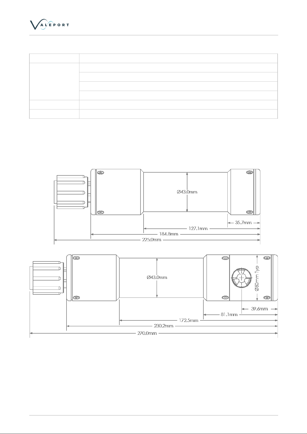
4.1. Dimensions
4.1.1. Standard VA500 Altimeter
Physical Characteristics
Page 9
© 2019 Valeport Ltd
Page 10

0430844c - VA500 Altimeter
4.1.2. VA500 Altimeter with 90° Transducer
© 2019 Valeport Ltd
Page 10
Page 11

Configuration and Operation
Valeport Terminal can be used to manually connect and configure
the VA500 or can be used in the configuration wizard mode.
Click on the configure button to launch the wizard.
Select the COM port the VA500 is connected to.
The wizard is configured with the default settings of the unit but
can be altered if the unit has been modified.
Default ASCII settings are pre-configured and should not need
changing.
5. Configuration and Operation
The VA500 is supplied with a Valeport Terminal, a terminal communications program and configuration tool
designed specifically for use with Valeport instruments.
Install the program by opening the install package on the supplied CD and follow the on screen instructions. Once
installed, launch the terminal program
5.1. Using The Configuration Wizard
Page 11
© 2019 Valeport Ltd
Page 12

0430844c - VA500 Altimeter
Select the VA500 altimeter from the drop down list.
Select the Read Configuration from the instrument to determine
current settings
Or
Open previously saved configuration file to load a predefined
setup.
The first wizard screen will give information about the instrument.
These are settings that are set at the factory.
The next page defines:
Communications settings.
Analogue mode and limits.(See wiring schedule in section 6 for
analogue outputs)
Analogue range can be 0-5V or 0-10V
Analogue limit is the distance that equates to full scale voltage
output.
Serial Data format (see data format section for definition of
formats)
The next page defines:
Output units, can be seconds, metres, feet or fathoms.
Minimum range allows fixed returns close to the VA500 to be
filtered out.
Maximum range allows filtering of spiking in noisy environments or
in the presence of multiple echoes.
Sound speed is set to 1500m/s. To improve accuracy then the local
sound speed should be measured and applied here.
Error is the value returned when no echo is detected or it is outside
the minimum and maximum ranges defined.
© 2019 Valeport Ltd
Page 12
Page 13
Configuration and Operation
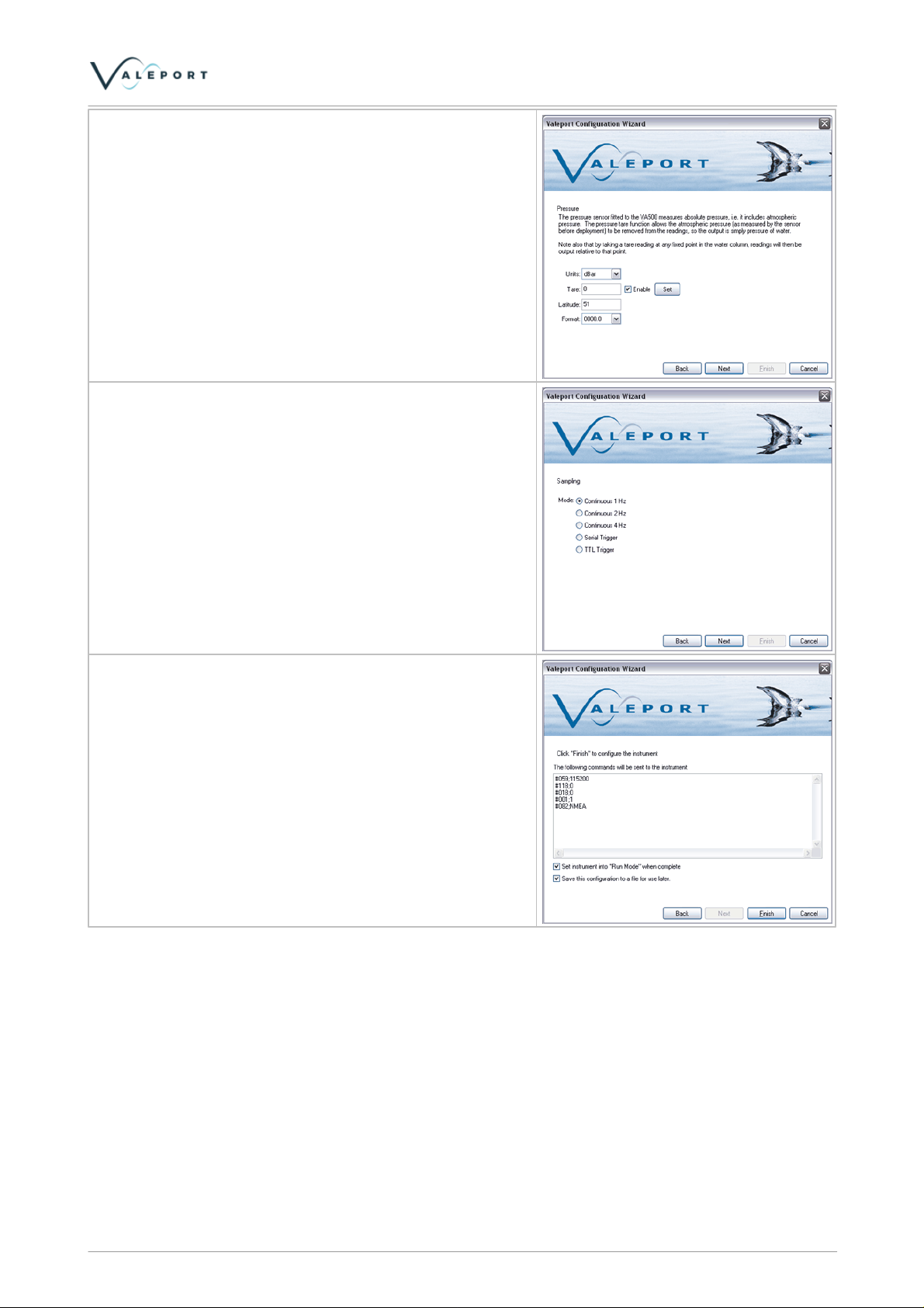
If the Altimeter is fitted with the optional pressure sensor, this can
be configured here.
Units can be dBar, metres or feet.
Tare allows the pressure sensor to be zeroed to atmospheric
pressure.
Latitude is used in the conversion from pressure to depth.
Continuous output rates can be 1,2 or 4 Hz
Alternatively the VA500 can be triggered with a serial command (S
followed by a carriage return) or via TTL (see wiring schedule in
section 6)
Once configuration is complete, the wizard will summarise the
commands to be sent to the instrument.
The configuration can also be saved to file for later use or
reference.
If the Run mode check box is ticked the instrument will start
outputting data into the terminal window behind once the
configuration is complete.
Page 13
© 2019 Valeport Ltd
Page 14

0430844c - VA500 Altimeter
Baud Rate:
115200 (can be 9600-115200)
Data Bits:
8
Parity:
none
Stop Bits:
1
Flow Control:
none
# code
Followed By:
Operation
#032
<CR>
Returns the software version number.
#034
<CR>
Returns the units serial number
#136
<CR>
Read PCB serial number
#138
<CR>
Send calibration date
#839
<CR>
Reads the transducer frequency
5.2. Manually Configuring The Unit
Alternatively the VA500 Altimeter can be manually configured via serial communications using a series of # code
commands. This can be with Valeport terminal or an alternative terminal program such as HyperTerminal.
Valeport Terminal is preconfigured with the required settings, but for reference the settings required to
communicate with the VA500 are:
Send line ends with line feed
The unit can be stopped at any time by sending the ‘#’ character. The unit returns a ‘>’, and waits for a further
command. The unit can then be interrogated or configured using the following codes.
Note that all commands must be “sent” by pressing the Enter (carriage return) key, with the exception of the single
‘#’ character required to enter setup mode
Note that there is a “watchdog” function here – if the unit is interrupted with the ‘#’ character, and no further
command is received for a period of 5 minutes, the sensor will automatically begin sampling data using the
existing settings.
5.3. Instrument Settings
© 2019 Valeport Ltd
Page 14
Page 15

5.4. Communications Settings
# code
Followed By:
Operation
#059
;baud_rate<CR>
Sets the units baud rate
2400,4800,9600,19200,38400, 57600,115200
RS485 is enabled by grounding a pin in the communications lead -
see Wiring Information
#001
;ALTIMETER_address<CR>
Sets the 485 address
#002
<CR>
Returns the address
#005
;ON<CR> or ;OFF<CR>
Turns ON or OFF address mode
#006
<CR>
Returns ON or OFF for address mode
Analogue Settings:
#094
;analogue_range<CR>
Sets the analogue output voltage range
0 – 0 – 5V
1 – 0 – 10V
#095
<CR>
Reads analogue output voltage range set
above
#096
;counts<CR>
Analogue output test.
#097
;Analogue range limit<CR>
Sets the range equivalent to full scale DAC
output
#098
<CR>
Reads the range equivalent to full scale DAC
output
Configuration and Operation
Page 15
© 2019 Valeport Ltd
Page 16

0430844c - VA500 Altimeter
# code
Followed By:
Operation
S
<CR>
Performs Single measurement
M
rate<CR>
Performs continuous measurement at set rate. If rate is
omitted then instrument performs continuous
measurements at previous rate.
1,2, or 4 Hz
#039
;ModeValue<CR>
Set mode without putting unit into run mode
Where
Mode = M
Value = 1,2 or 4 for Normal mode (M)
Mode = S for serial trigger single shot measurement
Mode = T for TTL trigger measurement
#040
<CR>
Read operating mode.
#028
<CR>
Puts unit into run mode
#089
<CR>
Reads current output format
#082
;SDDBT<CR>
;TRITEC<CR>
;BENTHOS<CR>
;NMEA<CR>
Sets output format (see section 4)
5.5. Sampling Regime
5.6. Output Format
See section 4 for detailed description of output formats
© 2019 Valeport Ltd
Page 16
Page 17

Configuration and Operation
# code
Followed By:
Operation
#021
;Range_units
Set to either
0 – Seconds
1 – Metres
2 – Feet
3 – Fathoms
#022
<CR>
Read range units set above
#118
;0 or 1 or 2<CR>
Set Altimeter Error output message
Where 0=zero (0.000), 1=-999, 2=NR
#119
<CR>
Reads Altimeter Error output message
#823
;maximum range<CR>
set the maximum range that is considered when
processing data (acoustic returns beyond maximum
range are ignored)
#824
<CR>
Reads maximum range
#840
;minimum range<CR>
set the minimum range that is considered when
processing data (acoustic returns before minimum
range are ignored)
#841
<CR>
Reads minimum range
#830
; Value, <CR>
Variable to change the Speed of Sound ms-1
#831
<CR>
Reads the sound speed
5.7. Range Settings
The VA500 has a standard operational range of 0.1m to 100m. If required this can be restricted with the setting of
a minimum range and maximum range.
The default setting for sound speed used to calculate range is 1500 m/s
Page 17
© 2019 Valeport Ltd
Page 18

0430844c - VA500 Altimeter
# code
Followed By:
Operation
#009
;<CR> or ;VALUE<CR>
Sets the tare value in systems with pressure fitted.
;<CR> = Makes device take a reading to use as
tare. ;VALUE<CR> = User entered value in units as set
by #018 command.
#010
<CR>
Returns the tare value
#011
;ON<CR> or ;OFF<CR>
Turns Tare function ON/OFF
#012
<CR>
Reads Tare mode
#016
;Latitude <CR>
Sets Latitude
#017
<CR>
Reads Latitude
#018
;Pressure units<CR>
Set to either
0 – dBar
1 – Metres
2 – Feet
#019
<CR>
Read pressure units
#083
;0 or 1 or 2 or 3
Setup the pressure output format
Where
0=not fitted, 1=PPPP.P, 2=PPP.PP, 3=PP.PPP
#084
<CR>
Returns the set pressure range
# Code
Followed By
Operation
#042
;0 or ;1
Enable/Disable DigiQuartz output telegram (appended to existing output)
#043
<CR>
Read DigiQuartz output (on or off)
#044
;0 or ;1
Enable\Disable DigiQuartz units (psia) text appended to DigiQuartz output
telegram
#045
<CR>
Read DigiQuartz units (psia) text appended to DigiQuartz output telegram (on
or off)
5.8. Pressure Settings
The pressure sensor fitted to the VA500 measures absolute pressure, i.e. it includes atmospheric pressure. The
pressure tare function allows the atmospheric pressure (as measured by the sensor before deployment) to be
removed from the readings, so the output is simply pressure of water. Note also that by taking a tare reading at
any fixed point in the water column, readings will then be output relative to that point.
5.9. Appended DigiQuartz Data Telegram (VA500P)
The VA500P can be configured to output an additional DigiQuartz type telegram appended to the conventionally
selected and configure telegram. This allows a separate pressure data telegram to be broadcast to an INS, for
example.
This DigiQuartz type telegram contains the instrument pressure reading in PSI, not corrected for latitude and the
tare NOT applied, i.e.PSIA.
In addition the psia unit can be included in the telegram if required.
These commands are not part of DataLOG x2. You will need to use a Terminal program to configure the
telegram.
See section Appended DigiQuartz Telegram (VP500P)
© 2019 Valeport Ltd
Page 18
Page 19

Output Telegram Formats
NB: This format limits the resolution of the altimeter to 0.1m
6. Output Telegram Formats
If the optional pressure sensor is fitted and enabled then the only data format that supports this is the Valeport
NMEA format. A number of other formats have been implemented to provide compatibility with existing systems.
6.1. Valeport NMEA Telegram ($PRVAT)
$PRVAT, xx.xxx,M, xxxx.x, dBar*hh<CR><LF>
Field Number:
1. Range from transducer
2. Units
3. Pressure
4. Units
5. Checksum
Example:
$PRVAT,00.115,M,0010.1,dBar*39
$PRVAT,00.116,M,0010.0,dBar*3d
6.2. $SDDBT Telegram
$SDDBT,x.x,f,x.x,M,x.x,F*hh<CR><LF
Sounder, Depth: Depth below transducer
Field Number:
1. Depth, feet
2. f = feet
3. Depth, meters
4. M = meters
5. Depth, Fathoms
6. F = Fathoms
7. Checksum
Example:
$SDDBT,0.4,f,0.1,M,0.1,F*02
$SDDBT,0.4,f,0.1,M,0.1,F*02
Page 19
© 2019 Valeport Ltd
Page 20

0430844c - VA500 Altimeter
6.3. Tritech Telegram
xx.xxxm<CR><LF>
Example:
00.126m
00.124m
6.4. Benthos Telelgram
Rxx.xx<cr><lf>
where xx.xx can range from 0.10 to 99.99. If no echo was received the output
will be R99.99E<cr><lf>.
Example:
R00.13
R00.12
© 2019 Valeport Ltd
Page 20
Page 21

Output Telegram Formats
6.5. Appended DigiQuartz Telegram (VP500P)
The VA500P can be configured to output an additional DigiQuartz type telegram appended to the conventionally
selected and configure telegram. This allows a separate pressure data telegram to be broadcast to an INS, for
example.
This DigiQuartz type telegram contains the instrument pressure reading in PSI, not corrected for latitude and the
tare NOT applied, i.e.PSIA.
In addition the psia unit can be included in the telegram if required.
See section Appended DigiQuartz Data Telegram (VA500P) for details on how to configure the data telegram.
without units:
*0001xx.xxx<CR><LF>
* = Start Character
00 = Destination ID (ID of Host - fixed)
01 = Source ID (ID of Device responding - fixed)
xx.xxx = Data – NO TARE applied (psia)
<CR><LF>
Telegram example:
Valeport NMEA telegram appended by the DigiQuartz type telegram (without psia units)
>#042;1 (enable DQ output)
>#028 (run)
$PRVAT,05.432,M,0010.076,dBar*39
*000114.614
$PRVAT,05.432,M,0010.066,dBar*38
*000114.600
with units:
*0001xx.xxxpsia<CR><LF>
* = Start Character
00 = Destination ID (ID of Host)
01 = Source ID (ID of Device responding)
xx.xxx = Data – NO TARE applied
psia = units
<CR><LF>
Telegram example:
Valeport NMEA telegram appended by the DigiQuartz type telegram (with psia units)
>#044;1 (enable units)
>#028(run)
$PRVAT,04.321,M,0010.084,dBar*34
*000114.626psia
$PRVAT,04.321,M,0010.067,dBar*39
*000114.601psia
Page 21
© 2019 Valeport Ltd
Page 22

0430844c - VA500 Altimeter
7. Care and Maintenance
There are no user serviceable parts within the VA500. The VA500 is remarkably robust, being primarily constructed
of titanium. The only maintenance required, other than periodic recalibration as necessary, is to keep the sensor
as clean as possible.
After use, rinse all parts in fresh water removing any growth or debris as necessary, but take exceptional care not
to touch or damage the pressure diaphragm itself if fitted.
7.1. Connector Care
The following handling procedures should be adopted when using connectors:
· The connector should not be exposed to long term heat or sunshine.
· If this occurs, and the connectors are very dry, soak in fresh water before use.
· Ensure the connectors are lubricated - the recommended lubricant is:
Loctite 8021 in a spray can
or
Molykote 44 Medium - but use very sparingly.
· Any accumulation of sand or mud in the female contact should be removed with fresh water. Failure to do so
could result in the splaying of the female contact and damage to the O-ring seals.
· When using bulkhead connectors ensure that there are no angular loads as this destroys the connector.
· When disconnecting, pull straight, not at an angle.
© 2019 Valeport Ltd
Page 22
Page 23

8. Wiring Information
SubConn
MCBH10F
Function
1
Power Ground
2
Power +V
3
Analogue +'Ve
4
Analogue -'Ve
5
Enable 485
Link to Pin 9 for RS485.
N/C for RS232
6
TTL trigger +Ve
7
RS232 Tx (To PC) / RS485A
8
RS232 Rx (From PC) / RS485B
9
RS232 Ground
10
TTL Trigger -'Ve
Wiring colours are correct at the time the manual was printed.
However, it is advised that continuity checks are performed prior to all terminations.
8.1. Instrument Connector
Wiring Information
Page 23
© 2019 Valeport Ltd
Page 24

0430844c - VA500 Altimeter
END1:
SubConn
MCIL10M
+ DLSA-M
END 2:
END 3:
9 Way D
Socket
FUNCTION
Pin
Connector
Pin
1
Black 4mm Plug
RS 444-797
-ve
2
Red 4mm Plug
RS 444-832
+ve
3
Analogue +ve
4
Analogue -ve
5
Enable 485
6
Trigger +ve
7
2
RS232 TX
(out of sensor)/RS485A
8
3
RS232 RX
(into sensor)/RS485B
9
1, 5, 6, 8, 9, SHELL
RS232 GND
10
Trigger -ve
8.1.1. Extended Y Lead - Power/232 Comms / Analogue
* Continue all connections through to the end of the full length of the cable
© 2019 Valeport Ltd
Page 24
Page 25

8.2. Non Standard Instrument Connectors
6 way Impulse
MCBH-6-MP
Function
1
RS232 Rx (into sensor / From PC)
2
Power Ground
3
RS232 Tx (from sensor / into PC)
4
Analogue +Ve
5
Analogue –Ve/ RS232 Ground
6
Power +V
Wiring Information
Page 25
© 2019 Valeport Ltd
Page 26

0430844c - VA500 Altimeter
END 1:
6 Way In Line
Female
Impulse
END 2:
Power In
END 2:
Analogue Out
END 3:
9 Way D
Socket
FUNCTION
Pin
Connector
Connector
Pin
2
Black 4mm Plug
-Vin6Red 4mm Plug
+Vin
4
Green 4mm Plug
Analogue
+ve
5
Black 4mm Plug
Analogue
-ve
3
2
RS232 TX
(out of sensor)
1
3
RS232 RX
(into sensor)
5
1,5,6,8,9
RS232 Gnd
6 way XSG-6-BCL
Function
1
RS232 Rx (into sensor / From PC)
2
Power Ground
3
RS232 Tx (from sensor / into PC)
4
Analogue +Ve
5
Analogue –Ve/ RS232 Ground
6
Power +V
8.2.1. Test Lead with 6 Way Female Impulse Connector
8.2.2. 6 Way XSG-6-BCL
© 2019 Valeport Ltd
Page 26
Page 27

8.2.3. Test Lead with 6 Way Female RMG-6-FS Connector
END 1:
6 Way In Line
Female Impulse
END 2:
POWER IN
END 2:
ANALOGUE OUT
END 3:
9 Way D Socket
FUNCTION
Pin
Connector
Connector
Pin
2
Black 4mm Plug
-ve in
6
Red 4mm Plug
+ve in
4
Green 4mm Plug
Analogue +ve
5
Black 4mm Plug
Analogue ve
3
2
RS232 TX
(out of sensor)
1
3
RS232 RX
(into sensor)
5
1,5,6,8,9
RS232
Gnd
(to mate to XSG-6-BCL)
Wiring Information
Page 27
© 2019 Valeport Ltd
 Loading...