

Page 1
UV-SVP
Operating Manual
Document Ref:
Date:
This document was prepared by the staff of Valeport Limited, the Company, and is the property of the
Company, which also owns the copyright therein. All rights conferred by the law of the copyright and by virtue
of international copyright conventions are reserved to the Company. This document must not be copied,
reprinted or reproduced in any material form, either wholly or in part, and the contents of this document, and
any method or technique available therefrom, must not be disclosed to any other person whatsoever without
the prior written consent of the Company.
Valeport Limited
St Peters Quay
Totnes
Devon, TQ9 5EW
United Kingdom
As part of our policy of continuous development, we reserve the right to alter, without prior notice, all
specifications, designs, prices and conditions of supply for all our equipment.
06508142b
28 September 2018
+44 1803 869292
sales@valeport.co.uk | support@valport.co.uk
www.valeport.co.uk
Tel:
e mail:
Web:
Page 2

Table of Contents
© 2018 Valeport Ltd
Page 2
Table of Contents
..................................................................................................................................... 31. EU Declaration of Conformity - CE Marking
..................................................................................................................................... 52. Introduction
..................................................................................................................................... 63. Specifications
..................................................................................................................................... 94. Data Requests
..................................................................................................................................... 115. Output Format
..................................................................................................................................... 126. Dimensions
..................................................................................................................................... 137. Wiring Information
Page 3
© 2018 Valeport Ltd
EU Declaration of Conformity - CE Marking
Page 3
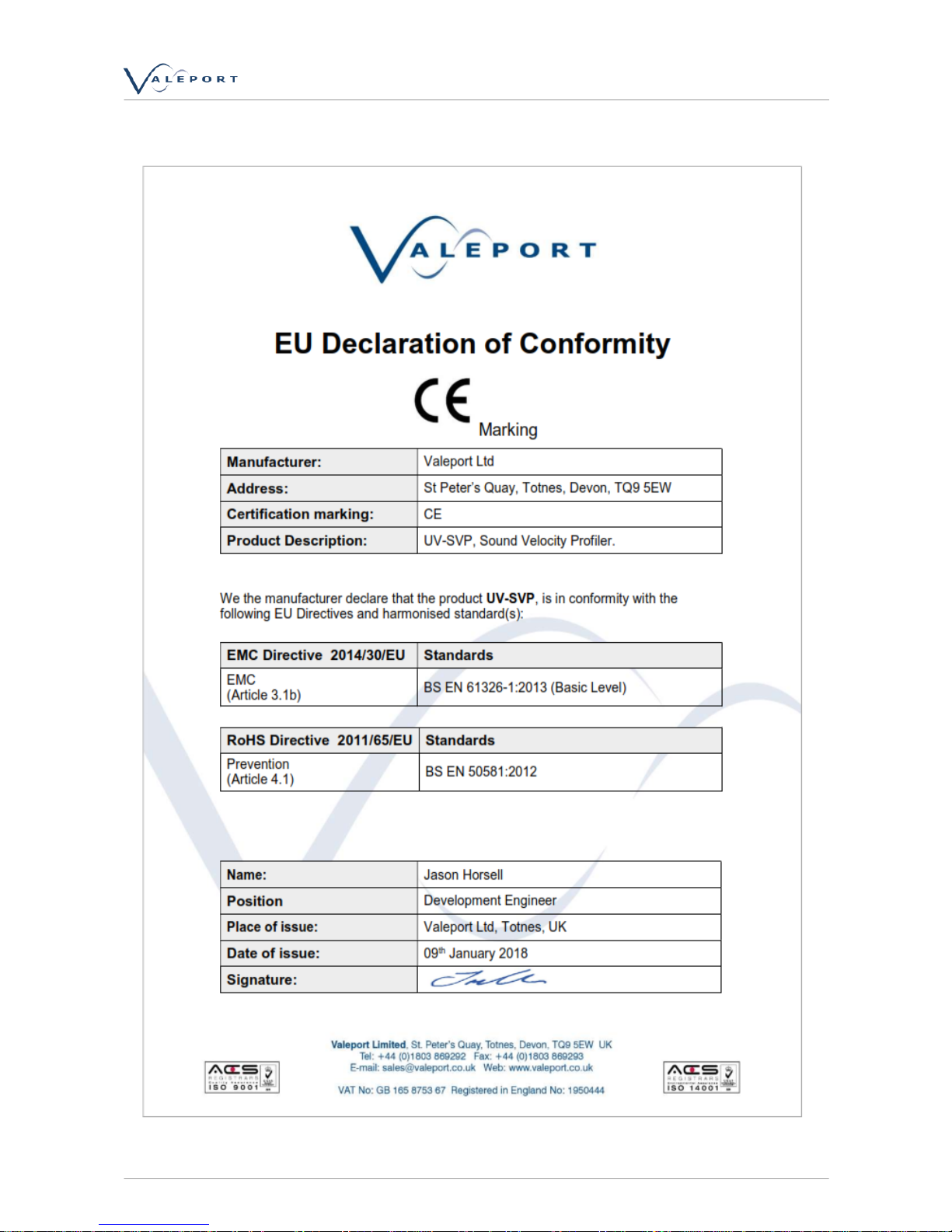
1. EU Declaration of Conformity - CE Marking
Page 4

© 2018 Valeport Ltd
06508142b - UV-SVP
Page 4
Please note: Any changes or modifications to the product or accessories supplied, that are not
authorised by Valeport Ltd, could void the CE compliance of the product and negate your authority
to operate it. This product has demonstrated CE compliance under conditions that include the use of
shielded cables. It is important that you use shielded cables compliant with the product’s
conformance, to protect from potential damage and reduce the possibility of interference to other
electronic devices.
Page 5

© 2018 Valeport Ltd
Introduction
Page 5
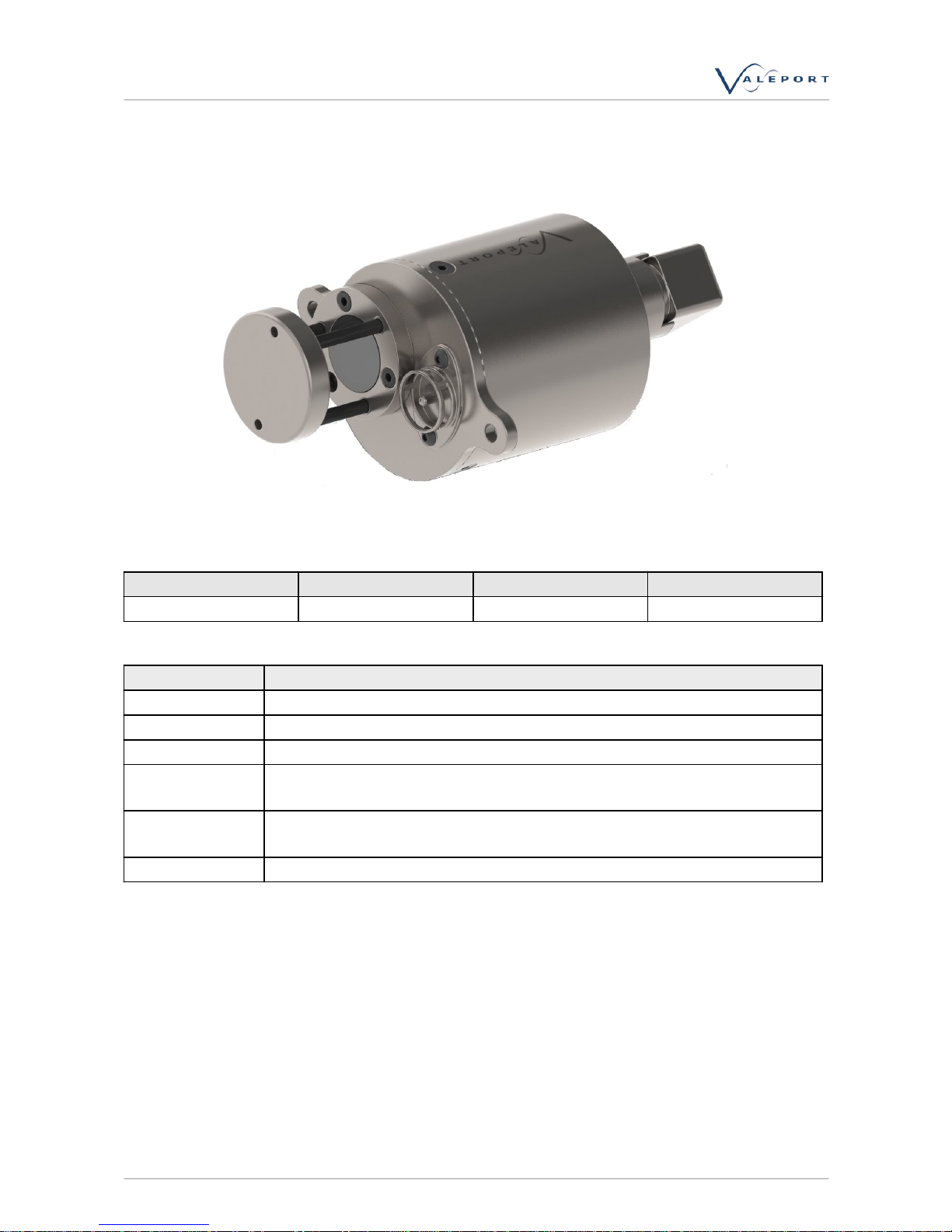
2. Introduction
This manual covers the basic specifications, deployment and maintenance procedures for the UVSVP. The instrument can be controlled by sending commands directly, using a suitable terminal
emulation program such as Valeport Terminal or HyperTerminal.
The instrument is based on Valeport’s existing “mini” sensor range and has been designed to be
simple to use and maintain, as well as being small and lightweight for easy handling and
deployment.
Page 6
© 2018 Valeport Ltd
06508142b - UV-SVP
Page 6
3. Specifications
Dimensions:
Housing Ø
Mounting bulkhead Ø
Overall length
Weight in Air
63mm
90mm
139mm
0.726 Kg
Materials:
Part
Material
Main housing
Titanium
Sensor bulkhead
Titanium
Connector
Titanium SubConn MCBH6F Right Angle
Sound Velocity
Sensor
Carbon Composite legs, Titanium Body, Ceramic Transducer behind
polycarbonate window
Temperature
sensor
Titanium
Pressure sensor
Hastelloy
Power:
External 9 – 28v DC input
0.36W (30mA @12v)
Page 7

© 2018 Valeport Ltd
Specifications
Page 7
Connection:
Standard is SubConn type MCBH6F titanium
Alternatives may be supplied on request
Wiring Information is in Section 4
Output:
Units are fitted with both RS232 and half-duplex RS485 communications as standard, selected by pin
choice on the output connector. Protocol is 8 data bits, 1 stop bit, no parity, and no flow control.
Baud rate is factory set to 19200. User may choose between 2400, 4800, 9600, 19200, 38400, 57600,
115200. (Note that fast data rates may not be possible with low baud rates). Continuous output at 1,
2, 4 or 8Hz
Performance:
Sensor
Sound Velocity
Range
1375 – 1900m/s
Accuracy
±0.02m/s
Resolution
0.001m/s
Frequency
2.5 MHz
Pressure
Range
10, 20, 30, 50, 100, 200 or 300Bar
Accuracy
±0.01% range
Resolution
0.001% range
Temperature
Range
-5 to +35°C
Accuracy
±0.01°C
Resolution
0.001°C
Certain features of the sensors used in the “mini” range are designed specifically to enable high
quality data to be delivered:
Carbon Composite Rods:
The carbon composite material used for the sensor spacer rods has been specifically selected to
provide 3 features:
a) Excellent corrosion resistance
b) Very high strength
c) Virtually zero coefficient of thermal expansion
This last point is particularly important; accurate sound velocity measurement relies on measuring
the time taken for a pulse of sound to travel a known distance. The material selected does not
measurably expand over the operating temperatures of the instrument, ensuring the highest possible
accuracy at all times.
Digital Sampling Technique:
Page 8

© 2018 Valeport Ltd
06508142b - UV-SVP
Page 8
Enables a timing resolution of 1/100th of a nanosecond, equivalent to about 0.5mm/sec speed of
sound on a 25mm path sensor, or 0.125mm/sec on a 100mm sensor. In practice, the output is
restricted to 1mm/sec resolution.
Linear sensor performance allows easy calibration.
Page 9

© 2018 Valeport Ltd
Data Requests
Page 9
4. Data Requests
The instrument responds to a series of text commands that are detailed below for those users who
wish to interface the UV-SVP to other systems.
This list is not comprehensive, but will allow the standard functions of the instrument to be accessed.
For more detailed information, please contact Valeport Ltd.
Notes
·
All commands must be confirmed using “Carriage Return” or “Enter” on the keyboard, with the
exception of the “Stop” command (#).
·
All commands are echoed back by the instrument as they are typed
Code
Followed By
Operation
#
Interrupts instrument when running
M
rate<CR>
Performs continuous measurement at set rate.
M1 = 1 Hz
M2 = 2 Hz
M4 = 4 Hz
M8 = 8 Hz
S
<CR>
Returns a single reading
#001
;address<CR>
Sets the 485 address
#002
<CR>
Returns the address
#004
<CR>
Read header info
#005
;ON<CR> or ;OFF<CR>
Turns ON or OFF address mode
#006
<CR>
Returns ON or OFF for address mode
#009
;<CR> or ;VALUE<CR>
Sets the tare value in systems with pressure fitted.
;<CR> = Makes device take a reading to use as
tare. ;VALUE<CR> = User entered value in units as set by
#018 command.
#010
<CR>
Returns the tare value
#011
;ON<CR> or ;OFF<CR>
Turns Tare function ON/OFF
#012
<CR>
Reads Tare mode
#018
;Pressure units<CR>
Set to either
0 – dBar
1 – Metres
2 – Feet
#019
<CR>
Read pressure units
#026
;valeport_separator<CR>
Sets the Valeport output string separator (1 char)
#027
<CR>
Returns the Valeport output string separator
#028
<CR>
Set the unit into run mode
#029
<CR>
Read run mode
#032
<CR>
Returns the software version number.
Page 10

© 2018 Valeport Ltd
06508142b - UV-SVP
Page 10
Code
Followed By
Operation
#034
<CR>
Returns the units serial number
#039
;ModeValue<CR>
Set mode without putting unit into run mode
Where
M1 = 1 Hz continuous output
M2 = 2 Hz continuous output
M4 = 4 Hz continuous output
M8 = 8 Hz continuous output
M16 = 16 Hz continuous output
#040
<CR>
Read operating mode.
#042
;ON or OFF
Enable/disable leading separator
#043
<CR>
Read leading separator (on or off)
#044
;ON or OFF
Enable/disable trailing separator
#045
<CR>
Read trailing separator (on or off)
#059
;baud_rate<CR>
Sets the units baud rate
2400,4800,9600,19200,38400;57600;115200
#083
;0 or 1 or 2 or 3
Setup the pressure output format
Where
0=not fitted, 1=PPPP.P, 2=PPP.PP, 3=PP.PPP
#084
<CR>
Returns the set pressure range
#091
;ON<CR> or ;OFF<CR>
Sets startup mode.
OFF=No readings at startup,
ON=Readings at last rate at startup
#102
;ON or OFF<CR>
Sets 485 mode
#103
<CR>
Sends 485 mode
Page 11

© 2018 Valeport Ltd
Output Format
Page 11
5. Output Format
Real time data follows the format described below.
Use #091 to control whether the instrument starts sampling as soon as power is applied or waits a for
command.
10.351 21.488 1506.739
·
The data separator is a space (this may be altered if required)
·
Leading and trailing spaces are enabled. (this can be altered if required)
·
Data is presented in the order:
- Pressure
- Temperature
- Sound Velocity
·
Pressure data format is dependent on sensor range, and may be any of the following. Leading
zeroes are included, so it is a fixed length string:
- PPPP.P (e.g. 0123.4 dBar)
- PPP.PP (e.g. 012.34 dBar)
- PP.PPP (e.g. 12.345 dBar)
·
The temperature data is given to 3 decimal places. Value is in °C and leading zeroes are included;
signed if negative:
- 21.456
- 02.769
- -01.174
·
Sound Velocity is given in m/s, as a fixed length string with 3 decimal places. In air, the sensor
reads 0000.000
Page 12

© 2018 Valeport Ltd
06508142b - UV-SVP
Page 12
6. Dimensions
Page 13

© 2018 Valeport Ltd
Wiring Information
Page 13
7. Wiring Information
Wiring colours are correct at the time the manual was printed. However, it is advised that continuity
checks are performed prior to all terminations.
Systems are supplied with a short (50cm) lead for splicing or testing
Subconn 6 pin male line (MCIL6M)
9 Way D Type
4mm Banana Plugs
Pin
Function
Pin
Pin
1
RS232 GND
5 (Link to 1,6,8,9)
2
RS232 Tx (Out of sensor) or RS485A
2
3
RS232 Rx (Into sensor) or RS485B
3
4+VRed Plug
5
Link to Pin 1 for RS485. N/C for RS232
6
Power GND
Black Plug
 Loading...