

Page 1
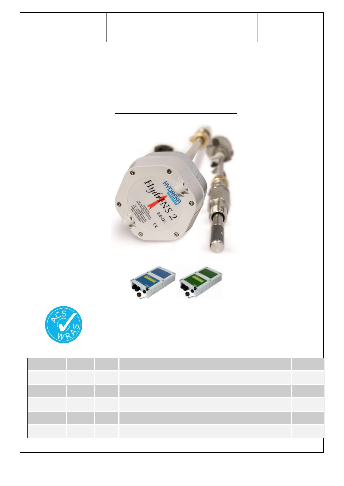
HydrINS 2 / HydrINS 2 Mini flow meter
Installation Manual
Page 1 / 83
Revision
Date
Author
Modifications
Signature
04
29/03/16
CBR
Downstream length and translation.FCC statement.
03
30/03/15
BLA
Lid closing procedure and SIM insertion
CBR
02
03/11/14
BLA
Update units (inches) add communicating display
CBR
01
15/02/2011
GSE
Approval
GSE
00
15/12/2010
MRE
Updated
HydrINS 2 and HydrINS 2 Mini
Electromagnetic Insertion Flow Meters
Installation Manual
Page 2

HydrINS 2 / HydrINS 2 Mini flow meter
Installation Manual
Page 2 / 83
CONTENTS
1 SAFETY INSTRUCTIONS .................................................................................................... 6
2 INTRODUCTION ............................................................................................................... 8
2.1 Measurement Principle ........................................................................................................... 9
2.2 Environmental and safety conditions ..................................................................................... 10
2.3 Conditions in the measurement environment ........................................................................ 10
2.4 Safety ................................................................................................................................... 11
2.5 Product transport .................................................................................................................. 12
2.6 Product guarantee................................................................................................................. 14
2.7 Conditioning the product before use ...................................................................................... 14
3 DESCRIPTION OF THE HYDRINS2 / HYDRINS 2 MINI PRODUCT RANGE ............................ 15
3.1 Mechanical description: ........................................................................................................ 15
3.2 Models in the HydrINS 2 / HydrINS 2 Mini flow meter range ................................................... 17
4 INSTALLATION LOCATION OF THE HYDRINS 2 / HYDRINS 2 MINI FLOW METER ............... 19
4.1 Choice of installation location and installation and flow conditions ........................................ 19
4.2 Velocity limits for measurement ............................................................................................ 20
4.3 Choice of position for the electromagnetic sensor .................................................................. 21
4.4 Typical installation of HydrINS 2 / HydrINS 2 Mini flow meters ............................................... 22
4.5 Inside diameter measurement gauges ................................................................................... 23
5 INSTALLATION OF THE HYDRINS 2 / HYDRINS 2 MINI FLOW METER ................................ 24
5.1 Method for installation at the centre: .................................................................................... 24
5.1.1 Step 1/3: Measuring the inside diameter DI using the gauge .................................................. 25
5.1.2 Step 2/3: Measure length of insertion at the centre LI
5.1.3 Step 3/3: Probe insertion ......................................................................................................... 27
........................................................ 26
1/2
Page 3

HydrINS 2 / HydrINS 2 Mini flow meter
Installation Manual
Page 3 / 83
5.2 Method for installation at 1/8 ............................................................................................... 28
5.3 Aligning the guide bar with the direction of flow .................................................................... 29
6 INSTALLING THE PRESSURE CHANNEL ON A DATA RECORDER ........................................ 30
7 VIEWING MEASUREMENTS BY DISPLAY OR RECORDING ................................................. 31
8 INSTALLATION OF A DISPLAY ......................................................................................... 32
8.1 Preview of Displays ............................................................................................................... 32
8.2 Mounting the display unit on a wall ....................................................................................... 33
8.3 Mode change of the HydrINS 2 and HydrINS 2 Mini probes ..................................................... 34
8.3.1 Equipment ................................................................................................................................ 34
8.3.2 Removal .................................................................................................................................... 34
8.3.3 Mode change ............................................................................................................................ 36
8.4 Closing the display lids .......................................................................................................... 38
8.5 Electrical power supply of Display A ....................................................................................... 39
8.5.1 Internal power supply using 3.6 VDC lithium batteries ........................................................... 41
8.5.2 External power supply using 3.6 VDC lithium batteries ........................................................... 41
8.5.3 Internal power supply using alkaline batteries ........................................................................ 42
8.5.4 External 9 to 28 VDC power supply connected to the internal terminals. .............................. 42
8.5.5 External power supply by military connector .......................................................................... 43
8.6 Electrical power supply of Display C ....................................................................................... 43
8.7 Electrical power supply of Display and Recording Unit ............................................................ 44
8.8 Wiring of the entities of the measurement chain .................................................................... 45
8.9 Internal wiring ...................................................................................................................... 48
8.9.1 Connections of the HydrINS probe to the Display terminal block ........................................... 48
8.9.2 Pulse output connections to the Display terminal block ......................................................... 49
8.9.3 Wiring the 4-20 mA outputs to the terminal block of Display C .............................................. 50
8.9.4 Wiring of the alarm outputs (Display A, C & G) ....................................................................... 51
Page 4

HydrINS 2 / HydrINS 2 Mini flow meter
Installation Manual
Page 4 / 83
8.9.5 SIM insertion with Display G & E .............................................................................................. 52
8.10 External connection to Display G & E .................................................................................. 53
8.11 Display G & E installation ................................................................................................... 53
8.11.1 FCC/IC compliance information ............................................................................................... 53
8.11.2 Installing Display G & E and the external antenna ................................................................... 55
9 TECHNICAL CHARACTERISTICS: ....................................................................................... 57
9.1 Hydrins II Probe ..................................................................................................................... 57
9.2 Display units ......................................................................................................................... 58
10 MAINTENANCE ........................................................................................................... 59
11 MAINTENANCE ........................................................................................................... 59
11.1 Calibration ......................................................................................................................... 60
11.2 Replacing the batteries of the HydrINS 2 / HydrINS 2 Mini flow meter ................................. 61
11.3 Replacing the display batteries ........................................................................................... 61
12 PRODUCT DISPOSAL ................................................................................................... 62
APPENDIX 1: SELECTION GUIDE: THE RIGHT HYDRINS 2 MODEL FOR YOUR MEASUREMENT
SITE ACCORDING TO YOUR PIPE ........................................................................................... 63
APPENDIX 2: INSIDE DIAMETER GAUGES .............................................................................. 72
APPENDIX 3: CATALOGUE NUMBERS ASSOCIATED WITH THE RANGE OF HYDRINS 2 / HYDRINS
2 PRODUCTS ........................................................................................................................ 73
APPENDIX 4: TEMPLATE FOR HYDREKA CALIBRATION CERTIFICATE FOR THE HYDRINS 2 /
HYDRINS 2 MINI FLOW METER ............................................................................................. 77
TABLE OF ILLUSTRATIONS .................................................................................................... 78
LIST OF TABLES .................................................................................................................... 80
Page 5

HydrINS 2 / HydrINS 2 Mini flow meter
Installation Manual
Page 5 / 83
Qualified personnel:
The electromagnetic insertion flow meter described in this document must be handled only by
personnel qualified for each specific task. The documentation concerning this task must be obeyed.
This applies in particular to safety instructions and warnings. Thanks to their training and experience,
qualified persons are able to recognise and avoid the risks involved in handling this electromagnetic
insertion flow meter.
Use of the flow meter and its display unit for their intended purpose
Remember the following points:
HYDREKA products must only be used for the applications described in the catalogue and the related
technical documentation. Their use in conjunction with products and components from other brands
is subject to HYDREKA approval. For the products to operate properly and safely, they must be
transported, stored, installed, assembled, commissioned, used, and maintained in accordance with
good professional practice. The allowable environmental conditions and the recommendations in the
related documentation must be observed.
Disclaimer:
We have checked the compliance of the contents of the present document. We are however unable
to rule out the possibility of any discrepancy, and cannot guarantee complete compliance. If any
errors are discovered during the use of this manual, we will make a note of them and make the
necessary corrections in the next edition.
Page 6

HydrINS 2 / HydrINS 2 Mini flow meter
Installation Manual
Page 6 / 83
1 Safety instructions
For the flow meter and its display unit to operate properly and safely, they must be transported,
stored, positioned and assembled in accordance with precise rules, and must be used and
maintained with care. This equipment must be installed and used exclusively by qualified
personnel.
No alterations to the equipment are permitted, including opening it or making inappropriate
modifications.
If this instruction is not obeyed, the CE marking and the guarantee will cease to be valid.
This equipment includes lithium batteries, which can cause a hazard if misused. Obey the
following rules:
Do not short-circuit or charge the batteries or reverse the polarity.
Do not expose the batteries to temperatures outside the specified range. Do not
incinerate them.
Do not crush, puncture, or open the cells. Do not disassemble the battery packs.
Do not solder the body of the batteries.
Do not expose the batteries or packs to water.
When returning the devices for calibration or maintenance:
Lithium batteries are classified as dangerous goods in accordance with dangerous goods
regulations UN 3090 and UN 3091. These directives impose the use of special transport
documents.
In accordance with EC Directive 2006/66/EC, batteries must not be disposed of with domestic waste.
NOTE: Must not be used in explosion-hazard areas!
Devices used in explosion-hazard areas must be Ex approved and marked as such. This device
is not approved for use in explosion-hazard areas!
Page 7
HydrINS 2 / HydrINS 2 Mini flow meter
Installation Manual
Page 7 / 83
This document is the user manual for the following electromagnetic insertion flow meter: HydrINS
2/HydrINS 2 Mini in the configuration with or without displays.
For acquisition programming, refer to the HydrINS 2 / HydrINS 2 Mini flow meter programming
manual, or the programming manual for the data logger used.
For additional information, please contact us:
HYDREKA
34, route de Saint Romain – 69450 ST CYR AU MONT D’OR – France
Tel: +33 (0)4 72 53 11 53 – Fax: +33 (0)4 78 83 44 37
Email: hydreka@hydreka.fr or accueil@hydreka.fr
Customer Service: Cservice@hydreka.fr
Rental: rent@hydreka.fr
Sales: sales@hydreka.fr
Export: export@hydreka.fr
Page 8
HydrINS 2 / HydrINS 2 Mini flow meter
Installation Manual
Page 8 / 83
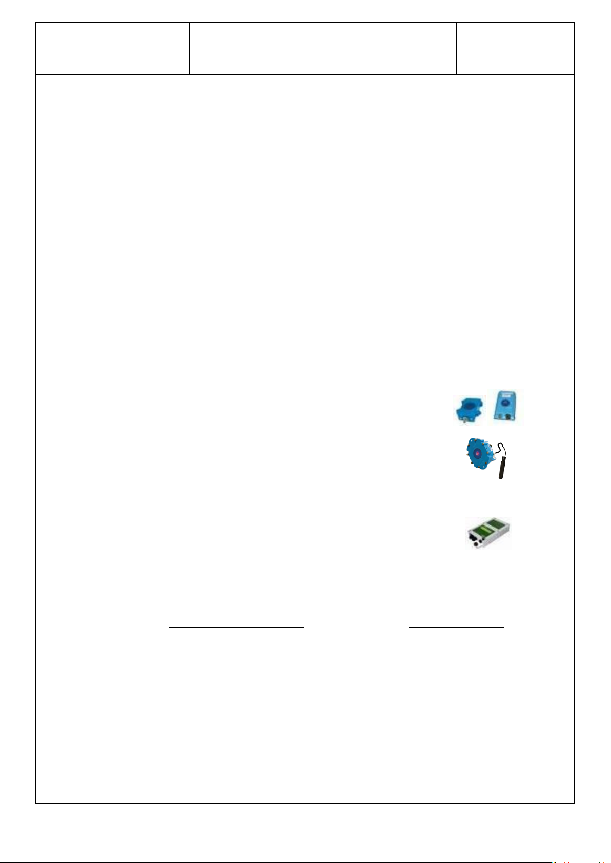
Connected to a standalone recorder with a digital input channel
(records data on site): Lolog, Vista +
Connected to a standalone recorder with a digital input channel with
communications capability (records data remotely): Octopus LX
Connected to a Display, (possibility of a Pulse or 4-20 mA output to a
remote management system or data transfer via the GSM network).
2 Introduction
The HydrINS 2/ HydrINS 2 Mini electromagnetic insertion flow meter is intended to measure flow in
pipes carrying drinking water or raw water. The probe performs a velocity measurement and
calculates the flow rate by integrating the velocity over the flow cross-section.
ACS certification and WRAS-certified materials.
The measurement scale is from 2 cm/s to 5 m/s (0.787 inches to 16.4 feet) and the relative
measurement accuracy is +/-2% or +/-2 mm/s (0.0787 inches), where the error applied is the larger
of the two.
The HYDREKA range of electromagnetic insertion flow meters comprises the HydrINS 2, which comes
in five standard lengths (300, 500, 700, and 1000 mm) and the HydrINS 2 Mini, covering diameters
from 70 mm (2.75 in) to more than 2000 mm (78.74 in).
Flow meters are installed using a 1" BSP or NPT insert collar equipped with a ball valve (also possible
using a 3/4" BSP or NPT collar for the HydrINS 2 Mini).
HydrINS 2 and HydrINS 2 Mini electromagnetic insertion flow meters can operate in several different
configurations:
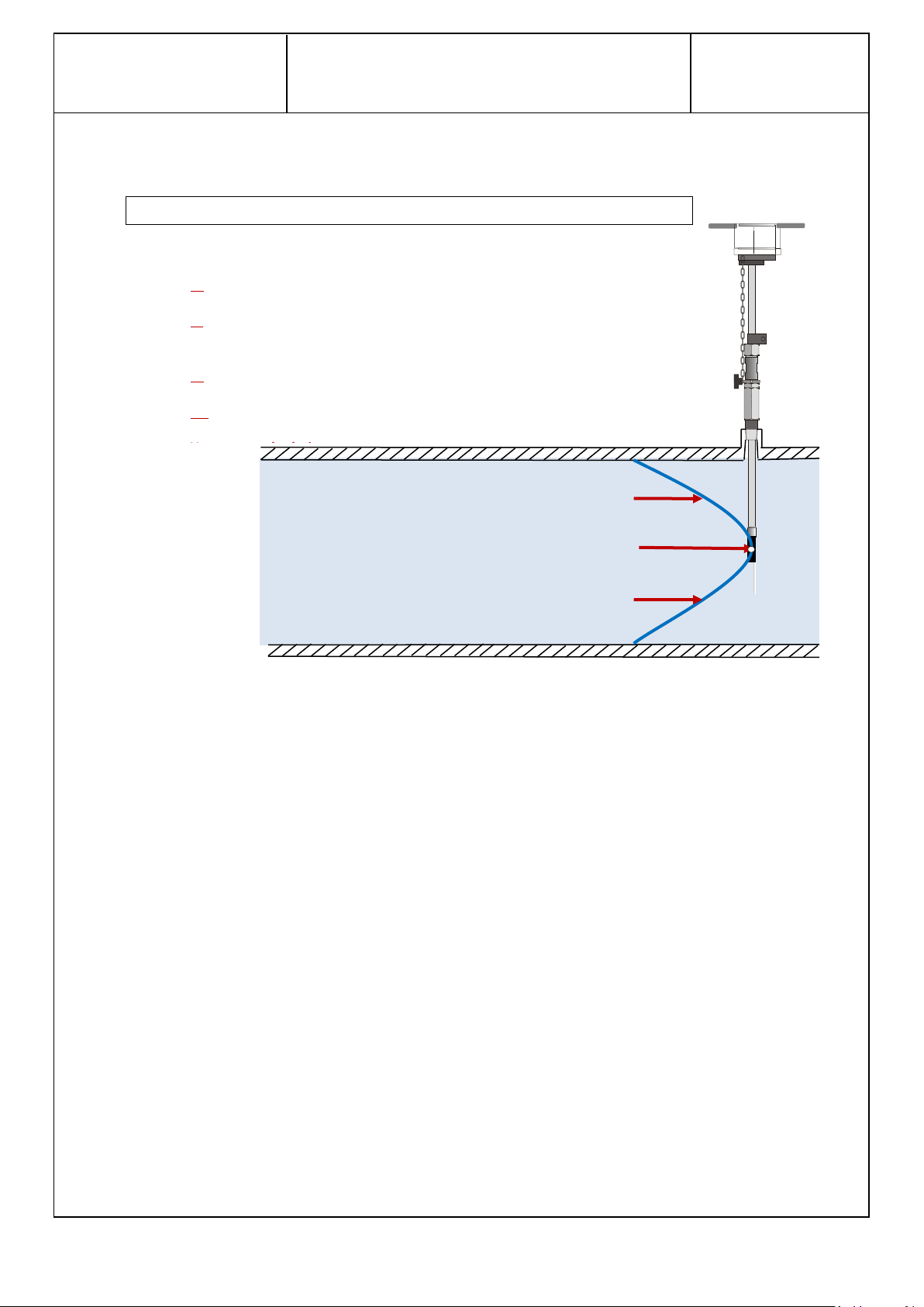
Two measurement positions are used for flow measurement:
The position at the centre of the pipe, which represents the maximum speed position
The position at one eighth of the diameter, which represents the mean speed position
The sensor of the HydrINS 2/HydrINS 2 Mini flow meter can be inserted in different positions across
the cross-section of the pipe. This allows a flow velocity profile to be created in order to refine the
mean speed calculation and therefore also the flow measurement. A set of default parameters is
available in the Winfluid software (refer to the HydrINS 2 / HydrINS 2 Mini Flow Meter
Programming Manual).
All Catalogue Numbers for the products presented in this manual are listed in Appendix 3.
Page 9
HydrINS 2 / HydrINS 2 Mini flow meter
Installation Manual
Page 9 / 83
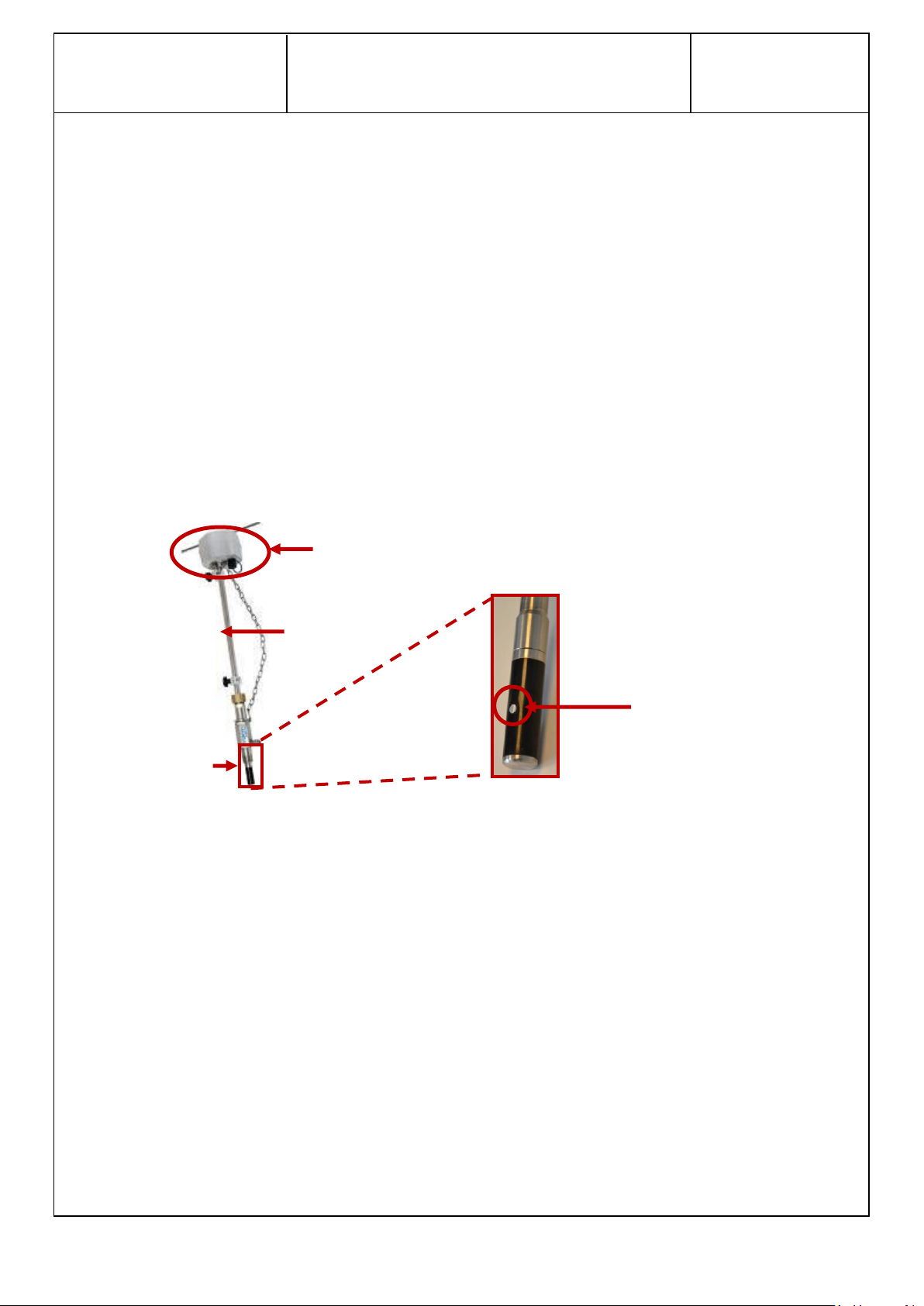
Probe head and guide bar
Insertion stem
Electrodes
Sensor
2.1 Measurement Principle
The velocity measurement principle is based on the application of Faraday's Law, which states that a
voltage is generated by the movement of a conductor through a magnetic field.
In the case of HydrINS 2/HydrINS 2 Mini, the magnetic field is generated by a coil at the end of the
probe, and the water passing through the pipe, whose conductivity must be at least 20 µS/cm,
represents the conductor.
The electromotive force generated by the passage of the water through the magnetic field,
comparable to a voltage, is measured by the two electrodes, which are visible on both sides of the
stem. Because this electromotive force is proportional to the velocity, the HydrINS 2/ HydrINS 2 Mini
probe carries out a velocity measurement derived from the electromotive force of the water. The
flow rate is then deduced from this velocity measurement.
The electromagnetic sensor is located at the tip of the insertion rod. It has an exciter coil and two
electrodes, seen on the side of the sensor.
Figure 1: Location of the sensor on the HydrINS2/HydrINS 2 Mini flow meter
Page 10
HydrINS 2 / HydrINS 2 Mini flow meter
Installation Manual
Page 10 / 83
Measured velocity Vm
Q = A × Fi × Fp × Vm
Where:
Q: flow rate
A: internal cross-section (calculated by Winfluid software from the inside diameter,
DI)
Fi: insertion factor (calculated by the Winfluid software)
Fp: profile factor (calculated by the Winfluid software)
The flow value is obtained via the following processing chain:
Figure 2: HydrINS 2/HydrINS 2 Mini data processing system
2.2 Environmental and safety conditions
Optimum use of the HydrINS 2 flow meter requires a suitable measurement environment in order to
avoid as far as possible any environmental disturbances that could affect the measurement.
Hydreka shall not be held liable for the quality of the measurements performed using the HydrINS 2 /
HydrINS 2 Mini flow meter if the recommendations given below are not observed.
2.3 Conditions in the measurement environment
Protection: IP 68 (NEMA 6):
HydrINS 2: 72 hours under 10 metres (32.8 feet)
Display units: 72 hours under 2 metres (6.56 feet)
Operating temperature range: -20°C (-4°F) to +60°C (140°F)
Storage temperature range: -20°C (-4°F) to +70°C (158°F)
Page 11
HydrINS 2 / HydrINS 2 Mini flow meter
Installation Manual
Page 11 / 83
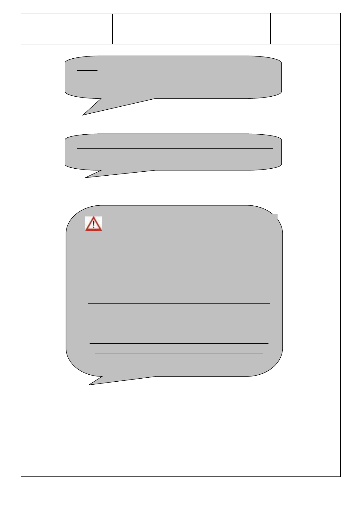
: A danger arises during the physical installation of the
HydrINS 2/HydrINS 2 Mini probe. Because of the intrusive nature of
the procedure, the probe can be ejected if there is excessive
pressure inside the pipe. The probe is supplied with a safety chain,
which must be used. Ensure compliance with the installation
conditions (pumps shut off, wait for night-time conditions before
installing, etc.).
ENSURE THAT THE CHAIN IS OPERATIONAL BEFORE OPENING THE
INSERT VALVE
PROPERTY DAMAGE CAUSED BY EJECTION OF THE PROBE IS NOT
UNDER ANY CIRCUMSTANCES COVERED BY THE GUARANTEE
THE CONDUCTIVITY OF THE WATER PASSING THROUGH THE PIPE
MUST BE GREATER THAN 20µS/cm.
NOTE: It is essential to avoid sites where the pipes vibrate. If the
probe vibrates excessively after installation, the measurement will
not be correct. In this case, remove the probe.
2.4 Safety
Page 12
HydrINS 2 / HydrINS 2 Mini flow meter
Installation Manual
Page 12 / 83
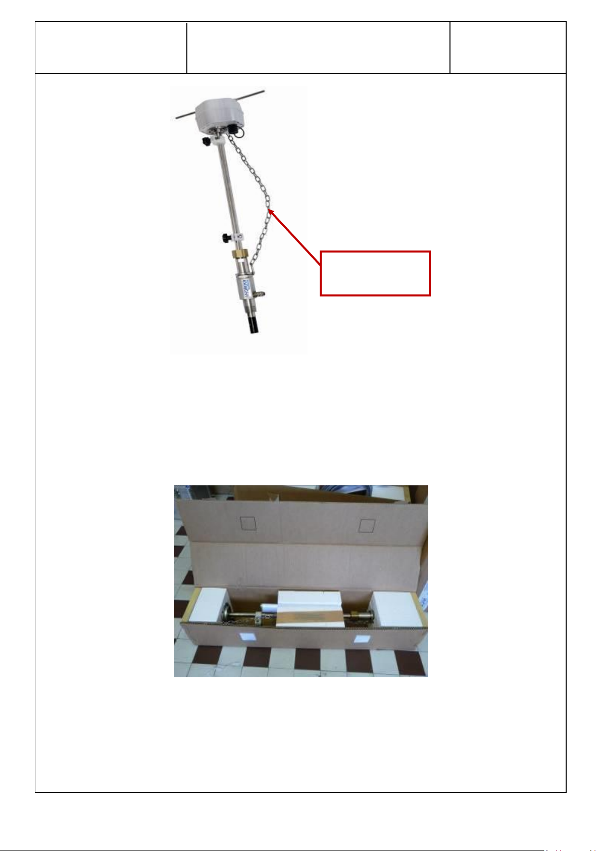
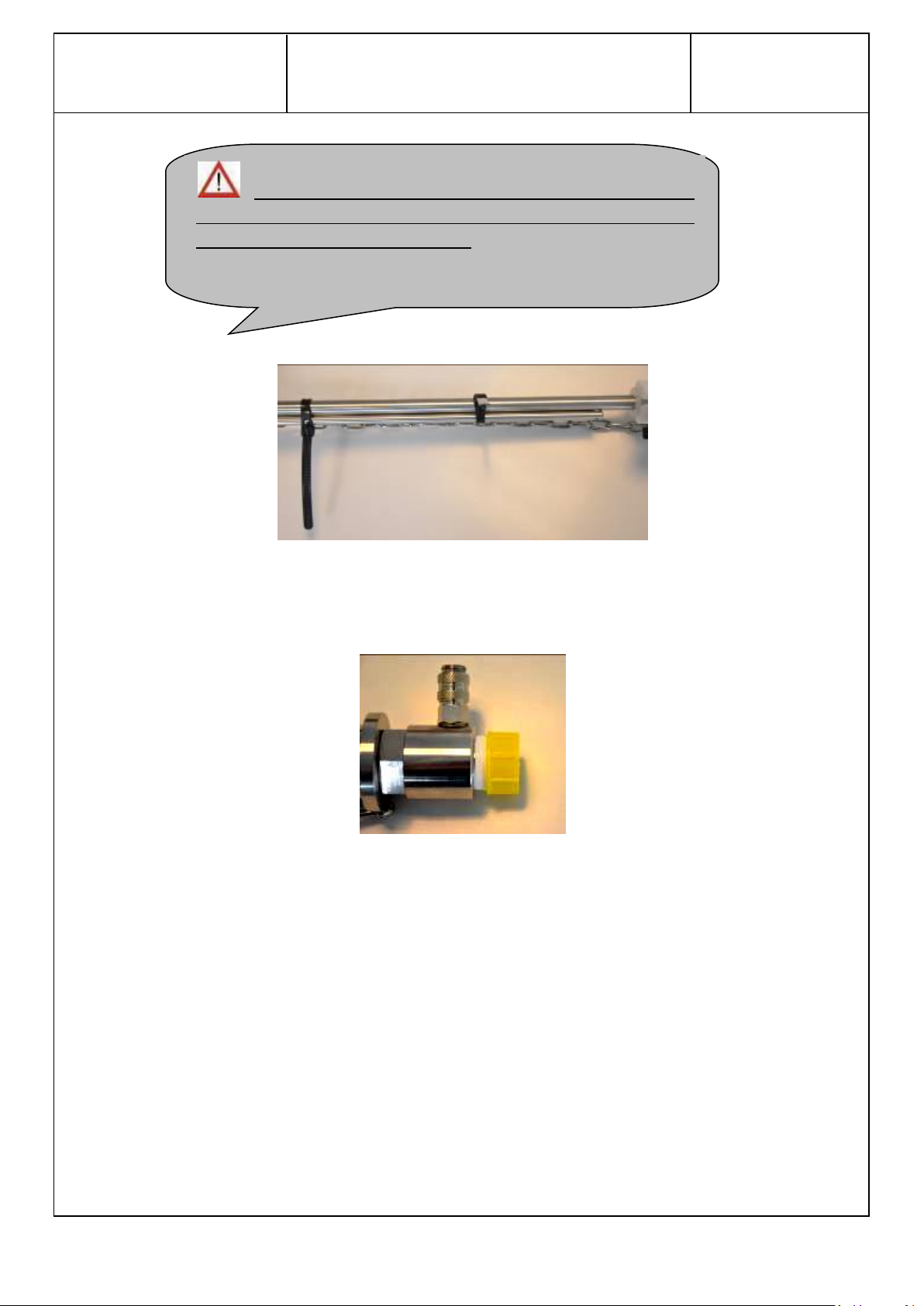
Safety chain
Figure 3: Safety chain
The safety chain is also used to ensure that the probe is fully reinstalled after the flow meter has
been removed. It is connected to a hook that can pivot around the probe.
2.5 Product transport
The HydrINS 2 / HydrINS 2 Mini flow meters are delivered in an appropriate box with polystyrene
blocks to protect them during transport.
Figure 4: Typical packaging of the HydrINS2/HydrINS 2 Mini
Page 13
HydrINS 2 / HydrINS 2 Mini flow meter
Installation Manual
Page 13 / 83
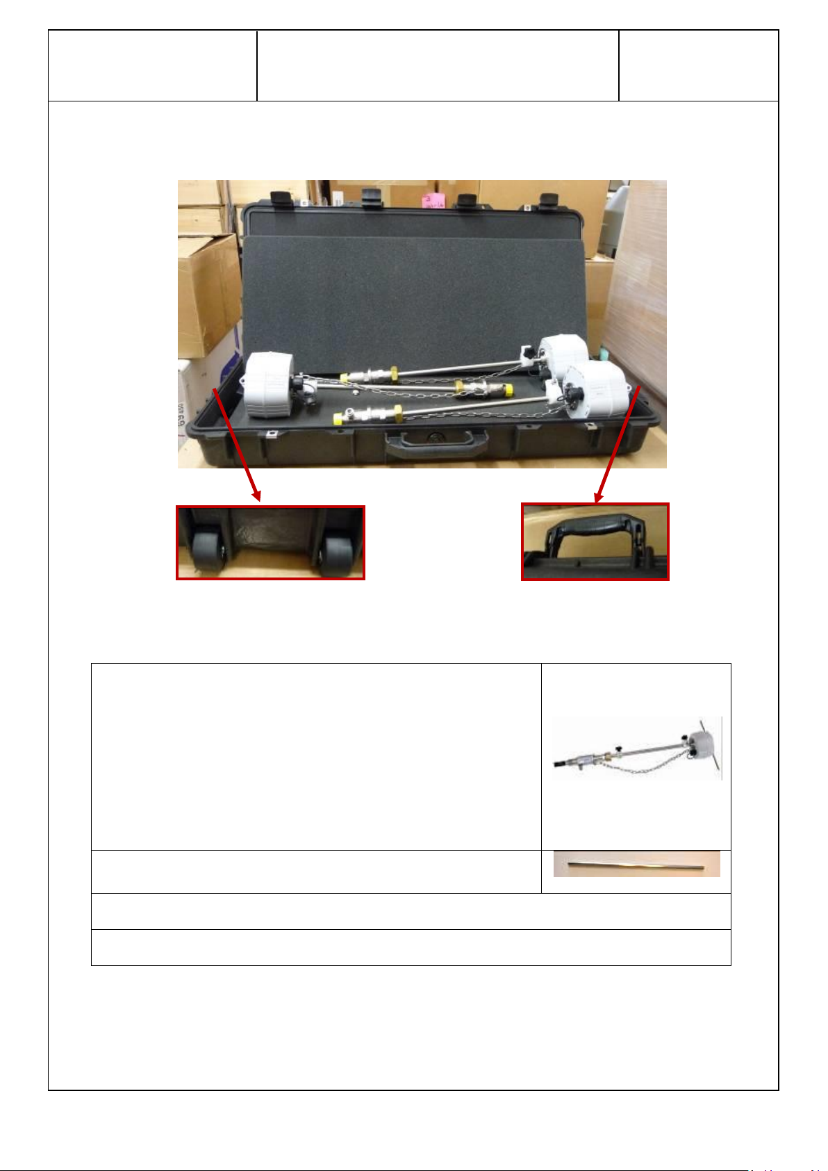
The HydrINS 2 / HydrINS 2 Mini flow meter with plug
Guide bar, attached or bonded to the flow meter
This installation manual
The programming manual
Reinforced cases, called PELICASE, are also available for the transport of HydrINS 2 / HydrINS 2 Mini
300 to 700 models and their accessories:
Figure 5: Pelicase transport case
Your package, whether a box or a case, must contain:
Page 14
HydrINS 2 / HydrINS 2 Mini flow meter
Installation Manual
Page 14 / 83
: ENSURE THAT THE GUIDE BAR IS IN THE PACKAGE. IT IS
ESSENTIAL FOR THE OPERATION OF THE HYDRINS 2 / HYDRINS 2 MINI.
IT IS CONNECTED TO THE FLOW METER
Figure 6: HydrINS 2 / HydrINS 2 Mini guide bar connected to the flow meter in the packaging
The HydrINS 2 / HydrINS 2 Mini flow meter is delivered with a protective plug. Please remove it
before installing the HydrINS 2 in the pipe.
Figure 7: Flow meter protection plug
2.6 Product guarantee
The HydrINS 2 / HydrINS 2 Mini has a three-year guarantee when used in accordance with the
conditions of use. Contact Hydreka Customer Service to invoke this guarantee if necessary.
2.7 Conditioning the product before use
The sensor of the HydrINS 2 / HydrINS 2 Mini flow meter must be soaked in water for one
day before use in order to obtain stable measurements.
Page 15
HydrINS 2 / HydrINS 2 Mini flow meter
Installation Manual
Page 15 / 83
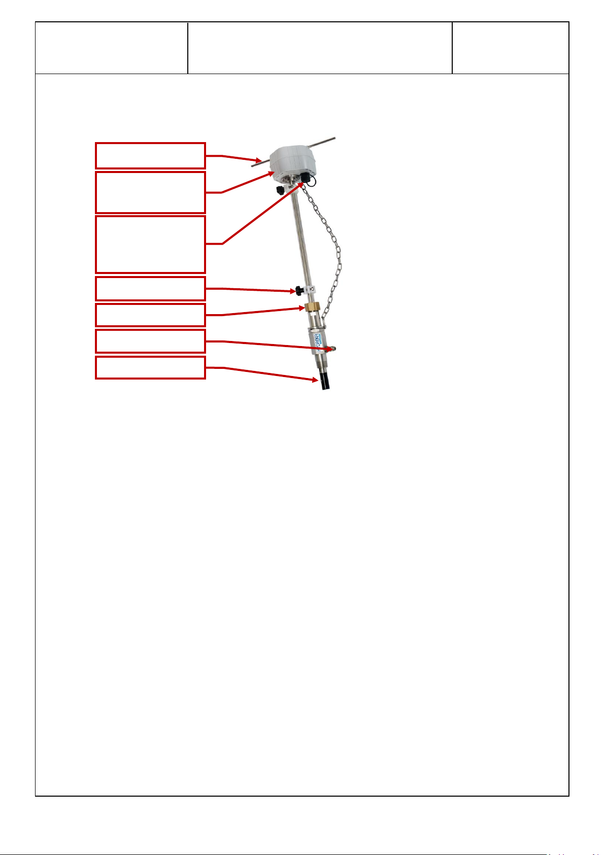
Probe head with
orientation arrow
Alignment stem
Communication
port and pulse
output
Insertion marking
Clamp ring
Pressure output
Sensor
3 Description of the HydrINS2 / HydrINS 2 Mini product range
3.1 Mechanical description:
Figure 8: Mechanical description of the HydrINS 2 / HydrINS 2 Mini flow meter
Page 16
HydrINS 2 / HydrINS 2 Mini flow meter
Installation Manual
Page 16 / 83
100
(3.93)
29
(1.14)
55
(2.16)
215
(8.46)
130 (5.42)
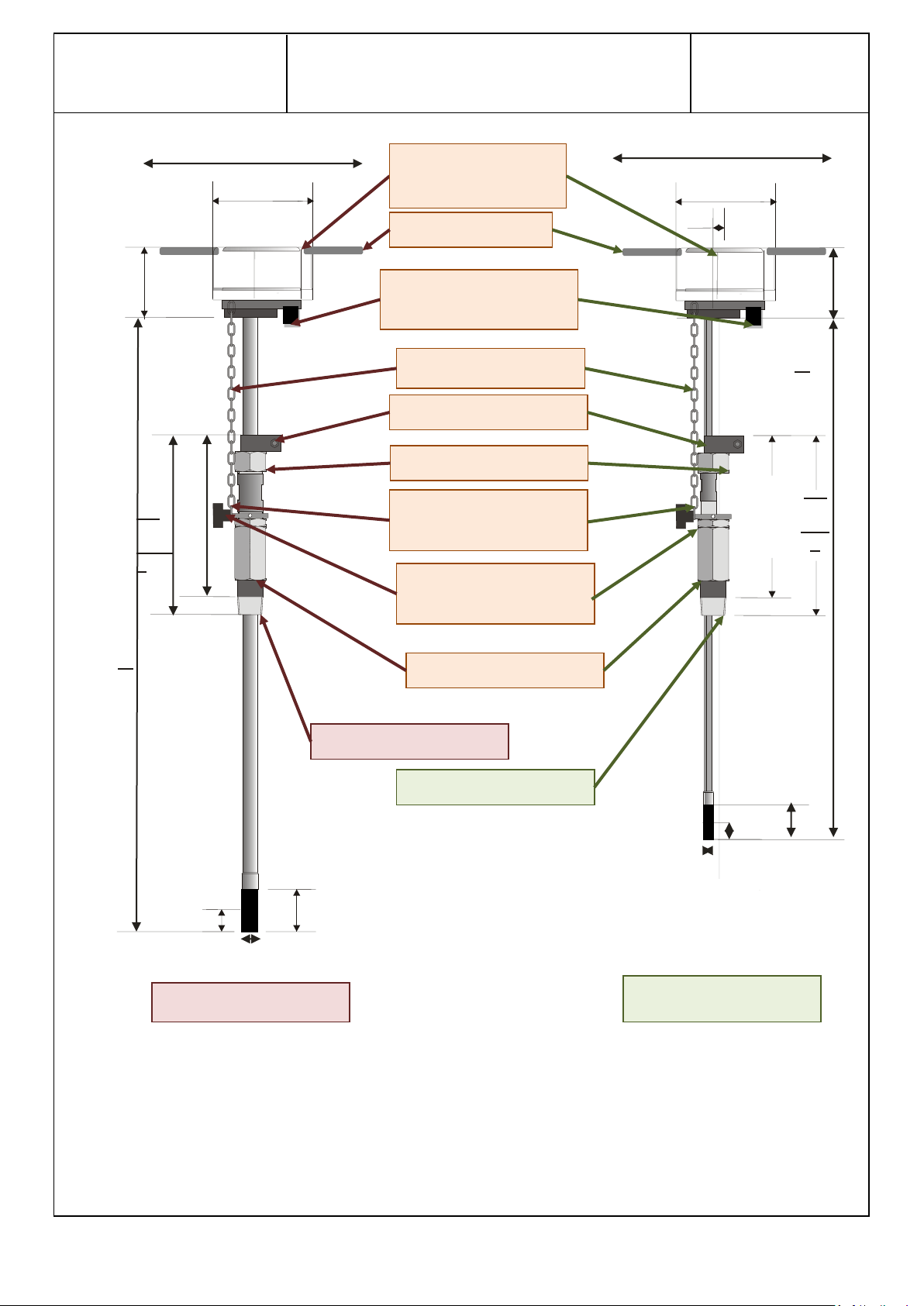
Alignment stem
Watertight military
connector
Insertion marking
Clamp ring
Adapter
1" BSP/NPT
Chain mounting ring
Chain attachment and
adjustment hook
Safety chain
Reinforced ABS
housing
100
(3.93)
50
(1.97)
22
50
(1.97)
145
(5.7)
130 (5.42)
HydrINS 2
HydrINS 2 Mini
3/4" BSP/NPT
300 (11.8)
300 (11.8)
15 (0.59)
21 (0.83)
234
(9.21)
B
165
(6.5)
B
A*
A*
*A: dimension A is 689(27.12) for Cat. No.: SI_HYDA2P-30 / 869(34.2) for Cat. No. SI_HYDA2P-50 / 1109(43.66)
for SI_HYDA2P-70 / 1409(55.47) for SI_HYDA2P-100 / 500(19.68) for Cat. No. SI_HYDE2-15
Dimensions in mm (inches)
Figure 9: Drawing of HydrINS 2 and HydrINS 2 Mini probes
Page 17

HydrINS 2 / HydrINS 2 Mini flow meter
Installation Manual
Page 17 / 83
HYDREKA
Catalogue
Number
Model
Hydrins
Dimension
A
mm
(inches)
Dimension
B
mm
(inches)
Dimension
C*
mm
(inches)
Available
insertion
length
= A-(B+C)
mm
(inches)
Usable on pipe
diameters
mm
(inches)
Profile
Centre
SI_HYDA2P-30
300
689
(27.12)
234
(9.21)
200
(7.87)
255
(10)
< 250
(9.84)
< 500
(19.68)
SI_HYDA2P-50
500
869
(34.21)
234
(9.21)
200
(7.87)
400
(15.75)
< 400
(15.75)
< 800
(31.5)
SI_HYDA2P-70
700
1109
(43.66)
234
(9.21)
200
(7.87)
675
(26.57)
< 650
(25.59)
< 1300
(51.18)
SI_HYDA2P-
100
1000
1409
(55.47)
234
(9.21)
200
(7.87)
975
(38.38)
< 950
(37.4)
< 1900
(74.8)
SI_HYDE2-15
Mini
500 (19.68)
165
(6.5)
200
(7.87)
175
(6.89)
< 180
(7.08)
< 300
(11.81)
3.2 Models in the HydrINS 2 / HydrINS 2 Mini flow meter range
The following table is a selection guide to identify the most appropriate HydrINS 2 model according
to the pipe diameter and dimensions as shown in the diagram above:
A: Total stem length (see the above diagram)
B: Stacking length of HydrINS 2/HydrINS 2 Mini accessories (see dimensions on the diagram
above)
C: Stacking height at insertion level (theoretical value, must be checked on site)
Table 7: Flow meter selection table according to the flow range to be measured
Note: This is a theoretical value. It is provided as an indication, but must be checked on site.
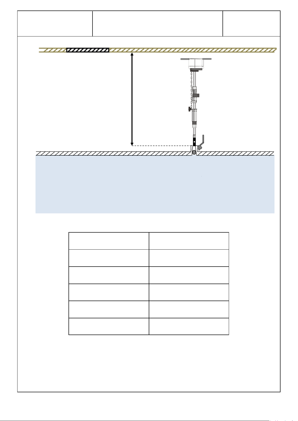
The model is also chosen according to the space available in the port. Allow sufficient distance above
the insertion point for installation in a port or valve chamber, known as the clearance height.
Page 18
HydrINS 2 / HydrINS 2 Mini flow meter
Installation Manual
Page 18 / 83
Model
Clearance height (mm) (in)
300
800 (31.5)
500
980 (38.6)
700
1220 (48)
1000
1520 (59.8)
Mini
610 (24)
Clearance height
The clearance heights are presented in the table below:
Table 7: Clearance heights above the insertion point required for installation of a HydrINS 2 / HydrINS 2 Mini flow meter.
Appendix 1 presents the HydrINS 2 / HydrINS 2 Mini flow meter models that can be used for several
standardised diameters.
Page 19
HydrINS 2 / HydrINS 2 Mini flow meter
Installation Manual
Page 19 / 83
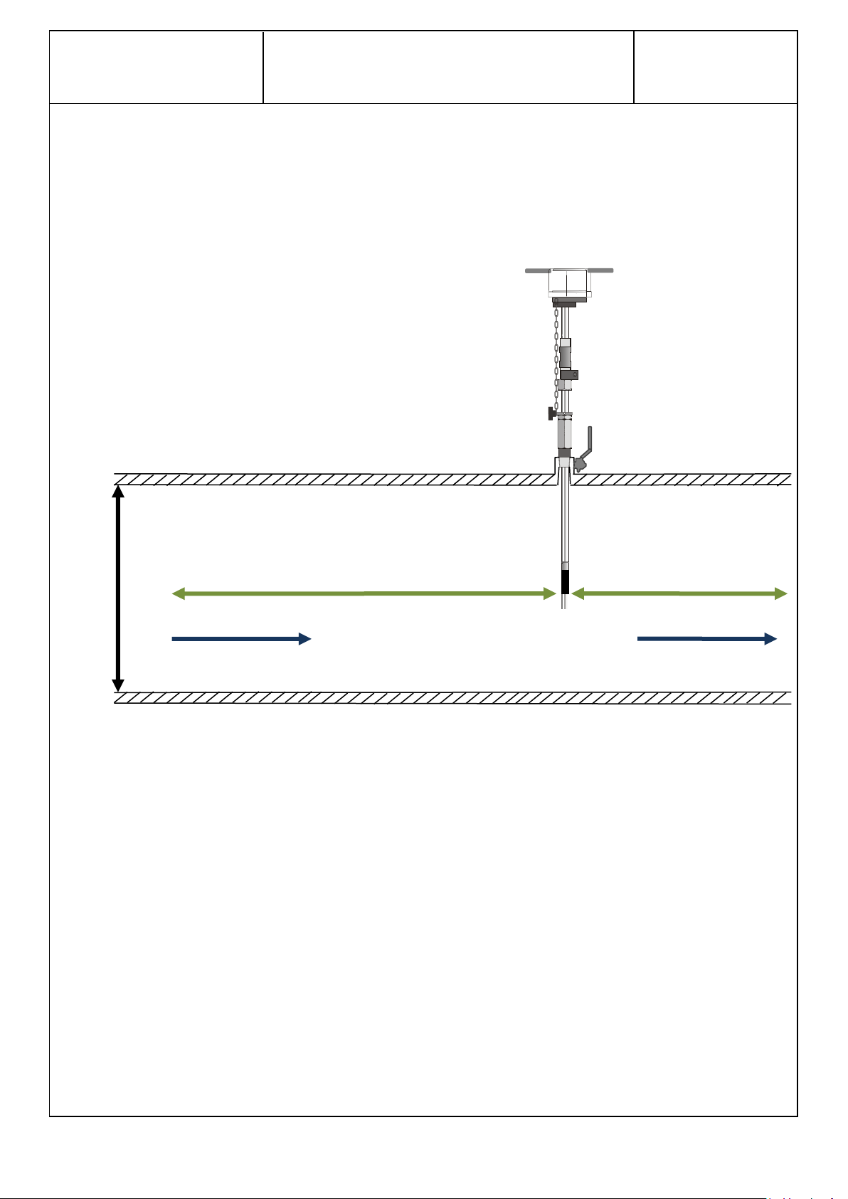
DI
UPSTREAM STRAIGHT LENGTH: See Table 1
DOWNSTREAM
STRAIGHT LENGTH:
5×DI
DIRECTION OF FLOW
*DI: inside diameter of pipe
4 Installation location of the HydrINS 2 / HydrINS 2 Mini flow meter
4.1 Choice of installation location and installation and flow conditions
For accurate measurement of the flow, the pipe must be continuously carrying a flow, and
disturbance-free upstream and downstream distances ('straight lengths') must be observed. The
table below summarises the upstream distances to be observed according to the disturbing element.
Figure 10: Flow conditions to be observed
Page 20
HydrINS 2 / HydrINS 2 Mini flow meter
Installation Manual
Page 20 / 83
Disturbances
Upstream straight length to be observed (multiple of
the internal diameter DI)
Measurement to the
centre
Measurement to 1/8th
90° connection or elbow
25
50
Convergent cone (18 to 36°)
10
30
Divergent cone (14 to 28°)
25
55
Open gate valve
15
30
Open butterfly valve
25
45
Table 1: Upstream disturbance-free straight lengths to be observed
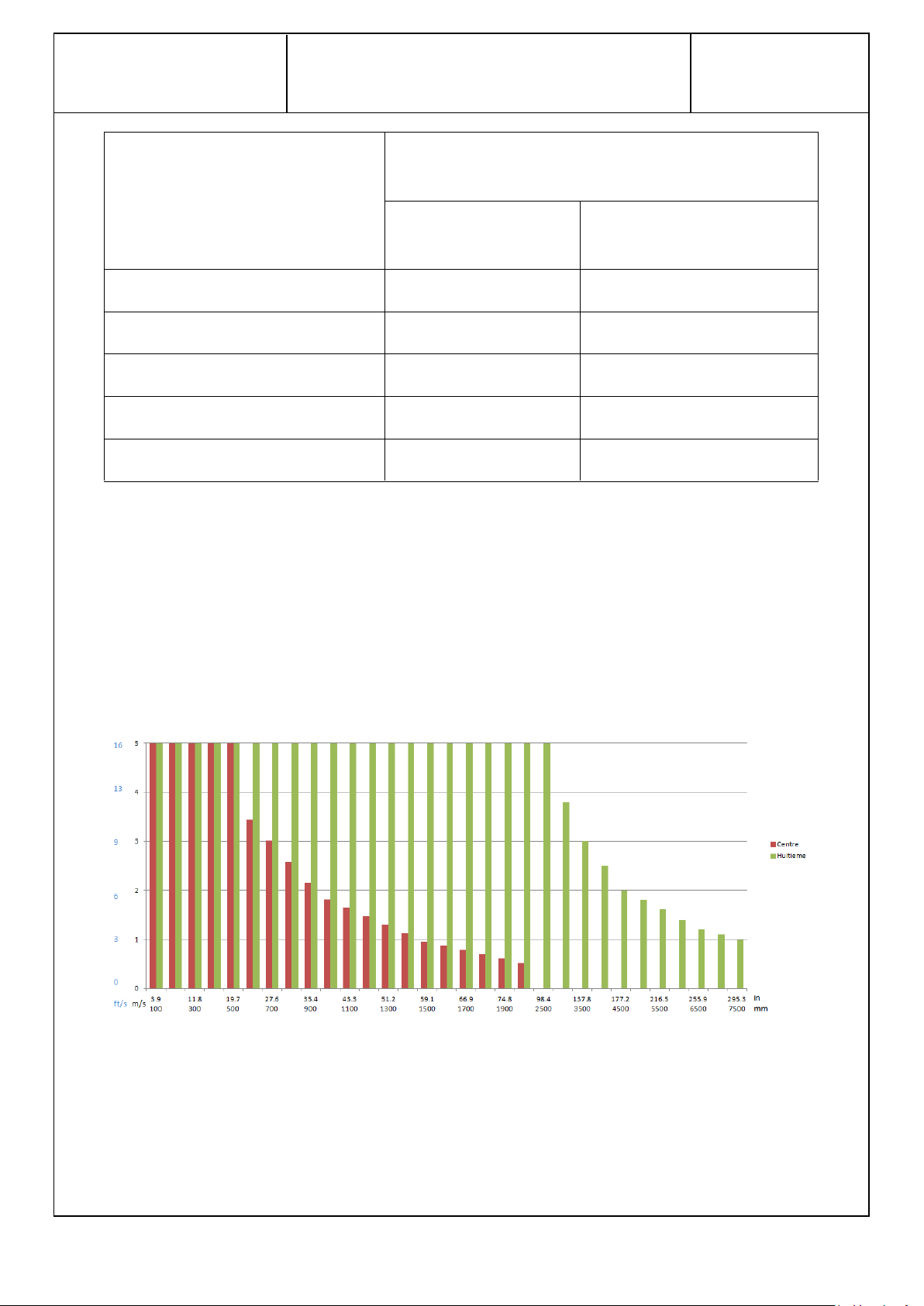
4.2 Velocity limits for measurement
Maximum velocities must be observed in order to prevent irreversible damage to the sensor. The
following charts show the maximum velocity applicable to the probe according to the chosen sensor
diameter and position. These values are provided as an indication. They are used when programming
the flow meter in Winfluid in the form of the maximum flow rate tolerated by the probe (refer to
the HydrINS 2 / HydrINS 2 Mini flow meter acquisition programming manual)
The flow rate is calculated based on a perfectly developed flow profile. Refer to the ISO 7145-1982
standard.
Figure 11: Maximum velocity for different pipe internal diameters
The creation of a velocity profile is used to refine the insertion factor and profile factor values (refer
to the HydrINS 2 / HydrINS 2 Mini flow meter acquisition programming manual). The order of
magnitude of the maximum velocities to be observed are indicated on the chart below.
Page 21

HydrINS 2 / HydrINS 2 Mini flow meter
Installation Manual
Page 21 / 83
Velocities not to be exceeded to achieve a velocity profile
Figure 12: Orders of magnitude of maximum velocities not to be exceeded to create a velocity profile
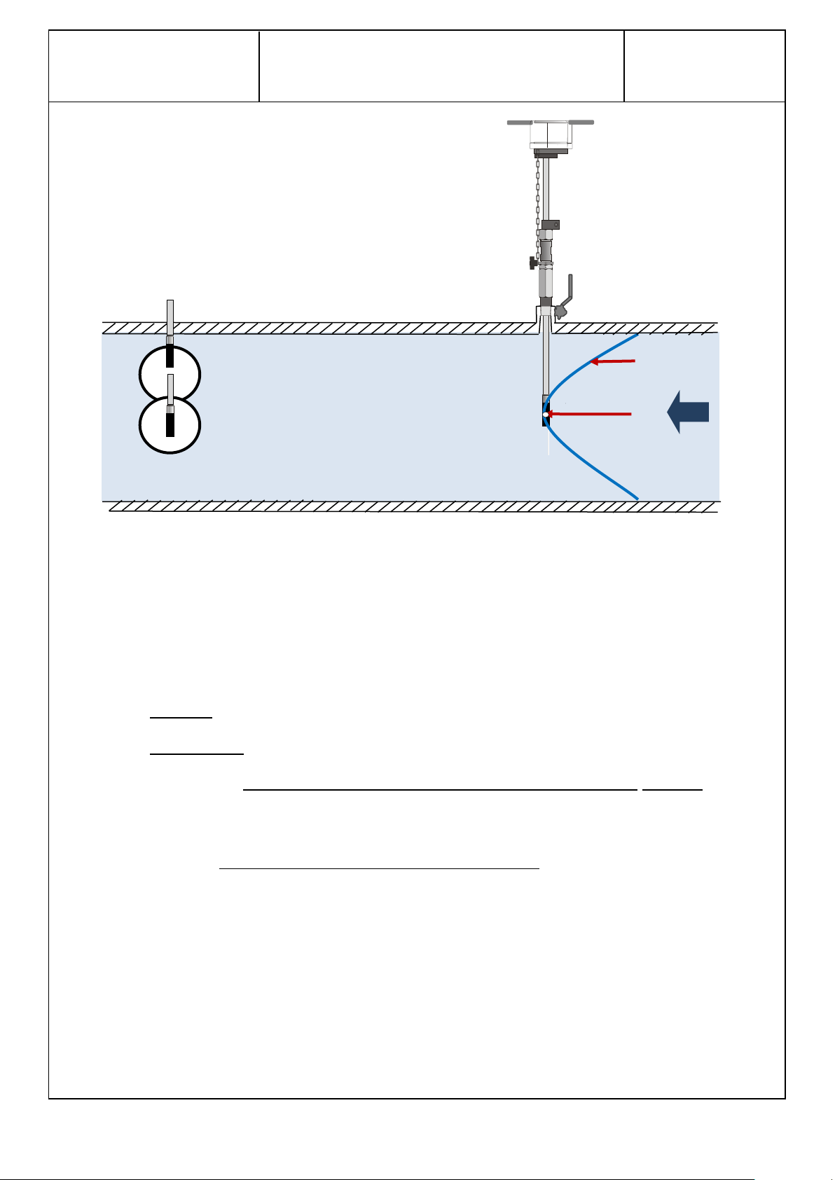
4.3 Choice of position for the electromagnetic sensor
Two precise positions are chosen for the electrodes in order to take a flow measurement:
At the centre of the pipe
At 1/8th of the pipe diameter
Page 22
HydrINS 2 / HydrINS 2 Mini flow meter
Installation Manual
Page 22 / 83
Position at 1/8 diameter
Position at 1/2 diameter
Figure 13: Valid positions of the HydrINS 2/HydrINS 2 Mini flow meter sensor for flow measurement
4.4 Typical installation of HydrINS 2 / HydrINS 2 Mini flow meters
Typical installations are as follows:
HydrINS 2: 1" insertion – drill 25 mm (0.98 inches) at least
HydrINS 2 Mini: two possibilities:
o Either 1" insertion plus 1"-3/4" adapter – drill 25 mm (0.98 inches) minimum: this
can measure the inside diameter of pipes using diameter gauges marketed by
HYDREKA and adaptable to 1" tappings.
o Or 3/4" insertion – drill 19 mm (0.75 inches) minimum: does not need an adapter.
The preparation of an insertion point compatible with HydrINS 2 or HydrINS 2 Mini is exactly the
same as for the preparation of a classic insertion point for the installation of a connection. No
additional accessories are required. After drilling the pipe, tighten the HydrINS 2 /HydrINS 2 Mini
probe to the ball valve.
Page 23
HydrINS 2 / HydrINS 2 Mini flow meter
Installation Manual
Page 23 / 83
Handle
Ring A
Ring B
1" thread
Stop of the
standardised length
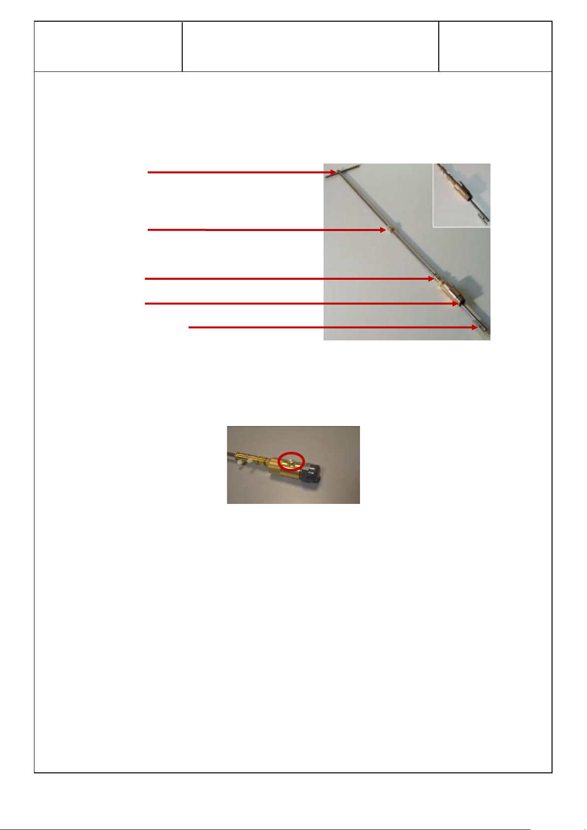
4.5 Inside diameter measurement gauges
Before the probe is installed, measurements may be performed using an adaptable diameter gauge
on a 1" insertion thread. Their use requires the appropriate clearance above the pipe.
Figure 14: View of the different components of the diameter gauge
The diameter gauge has a bleed screw to evacuate the pressure. This is useful when excessive
pressure prevents the user from bringing the gauge down to the bottom of the pipe.
Figure 15: Gauge pressure evacuator
Note that a gauge can be created with a personalised size and thread (please ask us). Available gauge
models and their sizes are described in detail in Appendix 2.
Page 24

HydrINS 2 / HydrINS 2 Mini flow meter
Installation Manual
Page 24 / 83
5 Installation of the HydrINS 2 / HydrINS 2 Mini flow meter
5.1 Method for installation at the centre:
The method for installing the probe at the centre, described below, includes three stages:
1. Measuring the inside diameter DI using the gauge. If the inside diameter cannot be
measured using the gauge, refer to the standardised characteristics of the pipes according to
their nominal diameters and materials. See example in Appendix 1.
2. Measurement of insertion length LI
3. Installation of probes at the calculated insertion lengths.
, as defined below.
1/2
Page 25
HydrINS 2 / HydrINS 2 Mini flow meter
Installation Manual
Page 25 / 83
Tighten the diameter gauge,
taking care to align the handle
with the pipe axis.
1. Open the insert valve and lower
the gauge until it stops against the
bottom of the pipe.
2. Lower the two identification
rings onto the gauge watertight
fitting.
3. Lock Ring A in this position using
the knurled screw.
1. Rotate the gauge through 180°.
2. Bring the gauge back up until it stops against
the upper surface of the pipe.
3. Position Ring B where it stops against the
watertight fitting of the gauge. Secure Ring B in
this position using the knurled screw
Measure the inside diameter
DI between the external faces
of the two rings.
DI
L
2 1 3
1
2
3
Ring A
Ring B
Freely
Immobilised
5.1.1 Step 1/3: Measuring the inside diameter DI using the gauge
It might not be possible to measure the DI (lack of space in the port or diameter too large). In that case, replace the DI value with an
estimate (e.g., manufacturer data).
Page 26

HydrINS 2 / HydrINS 2 Mini flow meter
Installation Manual
Page 26 / 83
1. From the last position,
place Ring A half-way along
the length L and lock Ring A
in position.
2. Loosen Ring B.
3. Rotate the gauge
through 180°.
1. Raise the gauge fully.
2. Close the insertion valve and place the tip of the gauge on the ball of the
valve.
1. Tighten Ring B.
2. Measure the insertion length LI
1/2
between the two internal faces of the
rings.
LI
1/2
1
2
1 2 L/2
1
3
2
L
5.1.2 Step 2/3: Measure length of insertion at the centre LI
1/2
Page 27

HydrINS 2 / HydrINS 2 Mini flow meter
Installation Manual
Page 27 / 83
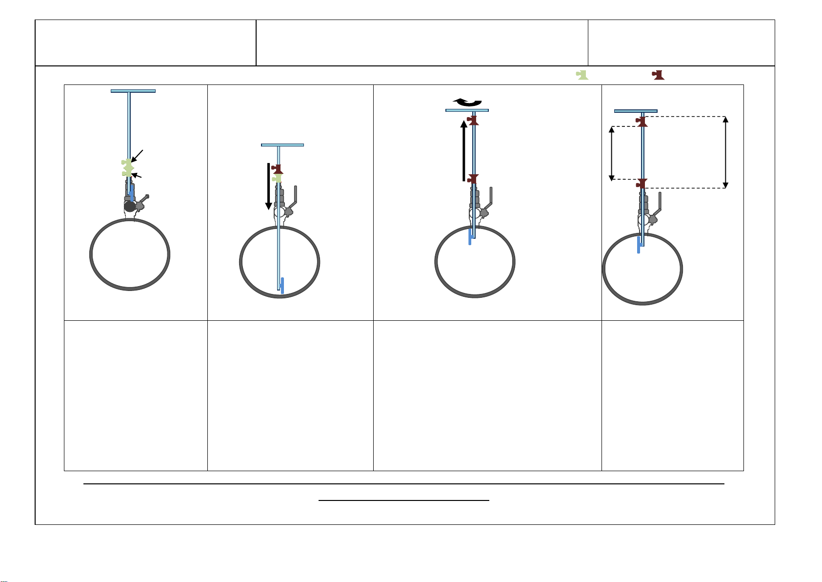
Installation at the centre
1. Close the insertion valve, tighten
the probe, and lower the probe until it
stops on the ball of the valve.
2. Place the insertion mark at the
insertion length LI
1/2
calculated above.
3. Open the insert valve and lower the
probe until the insertion mark stops
against the insert valve, and then
tighten the cable gland and adjust the
position of the safety chain.
3
LI
1/2
1
2
5.1.3 Step 3/3: Probe insertion
Page 28

HydrINS 2 / HydrINS 2 Mini flow meter
Installation Manual
Page 28 / 83
Figure 16: Diagram of installation at 1/8 diameter
For an installation at 1/8 diameter, the distance Z
1/8
after probe insertion
must be equal to:
Z
1/8
= L - E - 1/8 DI
Z
1/8
: Distance between the lower edge of the guide bar and the
top of the pipe (mm or in)
E: Pipe thickness (mm or in)
D: Inside diameter of pipe (mm or in)
L: Length (mm or in) – value according to model, equal to the
distance between the lower edge of the guide bar and the two
measurement electrodes located on the sensor
Model
L mm (inches)
300
760 (29.92)
500
935 (36.81)
700
1175 (46.26)
1000
1475 (58.07)
Mini
575 (22.64)
Table 2: Correspondence of lengths L with the HydrINS probe model for an installation at
1/8th diameter
Z
1/8
E
1/8 DI
DI
Guide Bar
5.2 Method for installation at 1/8
Page 29

HydrINS 2 / HydrINS 2 Mini flow meter
Installation Manual
Page 29 / 83
Main direction of flow
Correct arrow direction
Flow direction
Guide bar direction
5.3 Aligning the guide bar with the direction of flow
After adjusting the insertion distance and placing the flow meter in the desired position, tighten the
cable gland to maintain the position. The orientation of the HydrINS 2/ HydrINS 2 Mini flow meter
must now be adjusted. The head of the HydrINS 2 / HydrINS 2 Mini flow meter has a red arrow to
orient the flow meter in the main direction of flow. Flow in this direction will count as positive, whilst
flow in the reverse direction will count as negative.
Figure 17: Position of the positive direction arrow on the probe head
The guide bar supplied with the flow meter allows the electrodes to be positioned in the direction of
flow. Insert the bar in its lodging in the flow meter head, and then match the arrow with the positive
direction using the guide bar by placing it in the direction of flow.
Once the direction and alignment have been adjusted, tighten the cable gland more tightly to hold
the flow meter firmly in its final measurement position.
Figure 18: Aligning the flow meter in the direction of flow
Page 30

HydrINS 2 / HydrINS 2 Mini flow meter
Installation Manual
Page 30 / 83
Quickfit pressure
connection hose
Internal pressure
input
HydrINS 2 /
HydrINS 2 Mini
flow meter
pressure output
6 Installing the pressure channel on a data recorder
The HydrINS 2 / HydrINS 2 Mini insertion flow meter has a Quickfit connector to measure the
pressure at the same point as the flow measurement.
This channel can be connected to a recorder with an internal pressure channel (10 or 20 bars). This
applies to Lolog, Vista +, Octopus LX and other recorders.
Figure 19: Quickfit connector for the pressure channel between recorder and probe
To program acquisition on this channel, refer to the manual on Programming an internal pressure
channel.
Page 31

HydrINS 2 / HydrINS 2 Mini flow meter
Installation Manual
Page 31 / 83
7 Viewing measurements by display or recording
The flow data measured can be used in different ways:
Archived by a data recorder that supports a digital channel (Lolog, Vista +, Octopus LX, etc.)
or by an external system (SCADA or remote management)
Displayed on a display unit
Displayed on a Display and archived by an external recorder
Displayed and recorded by a Display recording unit
The displays show:
The flow rates (positive and negative)
The mean/instantaneous speed
The total normal/inverse/net volumes
Alarms
There are some noteworthy differences between the two display units:
With a Display A: The display unit can be equipped with batteries to obtain 10 years of
operating life. Two pulse outputs are available.
With a Display G &E and recording unit: Data are recorded and can be sent via the GSM
network. Two pulse outputs are available, with optional external power supply.
With a Display C: External 20-36 V DC power supply (from Serial Number 41754; if below,
then: 20-28 volts) with two 4-20 mA outputs (on terminal block) and four pulse outputs (two
on terminal block, two on output connector).
The HydrINS 2/HydrINS 2 Mini flow meter operates in two separate modes:
Mode 1 (without Display): The flow meter operates in standalone mode thanks to two
batteries in the head of the flow meter.
Mode 2 (with Display): The flow meter operates thanks to the power supply from the display.
A back-up battery is kept in the head of the flow meter. In the event of an interruption of the
electrical power supply from the display, this battery allows pulses proportional to the flow
rate to be sent until a normal electrical power supply is restored (except for Display C).
Page 32

HydrINS 2 / HydrINS 2 Mini flow meter
Installation Manual
Page 32 / 83
Configuration with pulse
output in bare wire to a
SCADA system
Configuration with a
standalone recorder
Configuration with
Display (standalone or
supplied from outside)
Mode 1
Mode 1
Mode 2
NOTE: This point is essential before putting the unit in operation. If an
incorrect operating mode is selected, the probe electronic board could
suffer irreversible electrical damage.
Figure 20: Installation configurations for HydrINS 2 / HydrINS 2 Mini
It is essential to ensure that the HydrINS 2 / HydrINS 2 Mini flow meter is configured in the
appropriate operating mode before placing it in operation; otherwise, the probe will suffer
irreversible damage (see paragraph 8.2).
8 Installation of a display
It is necessary to check in advance that the HydrINS 2/HydrINS 2 Mini flow meter is configured in
Mode 2 (see paragraph 8.23). It is important to specify that there is always the possibility of
communicating with the flow meter from a computer to perform checks or acquisition
reprogramming because the display is 'transparent' in communication between the computer and
the HydrINS 2 / HydrINS 2 Mini flow meter.
8.1 Preview of Displays
The Displays have cable gland fittings and/or military connectors and/or a TNC connector.
To reduce energy consumption, the display is activated manually using a magnet included with the
Display. This magnet must be applied to the area represented by the symbol
on one of the sides of the housing (Figure 22), to activate the Display. The display time is
adjustable when programming the probe.
Page 33

HydrINS 2 / HydrINS 2 Mini flow meter
Installation Manual
Page 33 / 83
Figure 21: Application of the magnet to the magnetic switch to activate the Display
Figure 22: Dimensions for wall-mounting a Display
237 mm
(9.33 in)
139 mm (5.47 in)
248 mm
(9.76 in)
154 mm (6.06 in)
Ф 5 mm
(0.2 in)
Magnetic
switch
8.2 Mounting the display unit on a wall
The Display can be mounted according to the following dimensions:
The substrate must have a perfectly flat surface.
Page 34

HydrINS 2 / HydrINS 2 Mini flow meter
Installation Manual
Page 34 / 83
Potential damage to the device. The internal electronic components of the device can
be damaged by static electricity, which might affect its performance characteristics and
operation.
8.3 Mode change of the HydrINS 2 and HydrINS 2 Mini probes
The change of the probe power supply mode must be performed with care. If not, there is a risk of
causing severe electrical damage to the flow meter.
8.3.1 Equipment
The following equipment is required to remove the HydrINS 2/HydrINS 2 Mini probe head:
Flat head screwdriver
3-mm Allen key
Brand new Silicagel bag
8.3.2 Removal
1 - Remove the six screws from the head of the flow meter:
Figure 23: Remove the screws from the head of the HydrINS 2 flow meter
2 – Remove the cover:
There are two possible cases:
It is possible to switch the probe from one mode to the other thanks to the light that is
present (see the indication below). In this case, after switching, immediately begin
reinstalling the reinforced ABS cover as explained below.
Page 35

HydrINS 2 / HydrINS 2 Mini flow meter
Installation Manual
Page 35 / 83
Position of numbers 1 and 2 for battery
(and mode) identification
1
2
Light to switch
between modes
without the need to
remove the yellow
battery holder.
No light is present, and in this case, it is necessary to identify and then remove Battery 1
and/or Battery 2, taking care not to pull the wires off, and then to disassemble as explained
below:
Figure 24: Overview of the inside of the HydrINS 2 flow meter head
Loosen the three flat-head screws securing the battery holder, and remove it.
Page 36

HydrINS 2 / HydrINS 2 Mini flow meter
Installation Manual
Page 36 / 83
Mode 1: WITHOUT DISPLAY (switch to the right)
Mode 2: WITH DISPLAY (switch to the left)
Figure 25: Removal of the cover from the head of the HydrINS 2 flow meter
8.3.3 Mode change
According to the desired mode, set up the configuration described below:
Page 37

HydrINS 2 / HydrINS 2 Mini flow meter
Installation Manual
Page 37 / 83
Internal
connection
Battery 1 kept
Figure 26: Mode 1/Mode 2 change and arrangement of batteries in the HydrINS 2 flow meter
Reinstall the cover using the alignment guides:
Figure 27: Locating guides for the head of the HydrINS 2 flow meter
Also be sure to reposition the foam, the new silicagel bag, and battery wire protectors (transparent
plastic).
Page 38

HydrINS 2 / HydrINS 2 Mini flow meter
Installation Manual
Page 38 / 83
8.4 Closing the display lids
Follow the instructions below to close the lids of display units (A,C,E and G)
1. Put the first lid in place by pushing "A" point then "B" point", hold in place then screw points
1 and 2 at 0.85 Nm.
2. Put the second lid in place by pushing "C" point then "D" point, hold in place then screw
points 3,4,5, and 6 at 0.85Nm.
Page 39

HydrINS 2 / HydrINS 2 Mini flow meter
Installation Manual
Page 39 / 83
Risk of electrocution. Always disconnect the power supply before making any electrical
connections.
Potential damage to the device. The internal electronic components of the device can
be damaged by static electricity, which might affect its performance characteristics and
operation.
8.5 Electrical power supply of Display A
Display A can be powered according to one of the following five modes:
Internal 3.6 VDC lithium battery pack
External 3.6 VDC lithium battery pack
Internal 9 to 28 VDC alkaline battery pack
An external 9 to 28 VDC power supply connected to the labelled 9-28 VDC terminals
A 9 to 28 VDC external power supply connected to the military connector
These different power supply modes can be implemented using the two elements illustrated below:
Switch SW2 with two positions: Internal or External
Connector J15
Page 40

HydrINS 2 / HydrINS 2 Mini flow meter
Installation Manual
Page 40 / 83
Connector J15
Connector SW2
Figure 28: Positions of Connector J15 and Switch SW2 inside Display A
In a case other than lithium battery power supply, an electronic board, Cat. No. 400511, is connected
to Connector J15. Two switches, SW1 and SW2, are present on this board.
Page 41

HydrINS 2 / HydrINS 2 Mini flow meter
Installation Manual
Page 41 / 83
8.5.1 Internal power supply using 3.6 VDC lithium batteries
1 – Create the following configuration:
Switch SW2: Internal
Connector J15: Connect 1-2 and 15-16
2 – Connect the battery pack in the upper compartment and close the cover of Display A.
Figure 29: Connection of the lithium battery
8.5.2 External power supply using 3.6 VDC lithium batteries
1 – Create the following configuration:
Switch SW2: External
Connector J15: Connect 1-2 and 15-16
2 – Connect the battery pack to the +/- 3.6 V positions of the POWER connector, observing the
polarities.
Figure 30: Position to use for an external 3.6 V power supply
Page 42

HydrINS 2 / HydrINS 2 Mini flow meter
Installation Manual
Page 42 / 83
8.5.3 Internal power supply using alkaline batteries
1 – Remove all connections from Connector J15, and then connect the additional board, Cat. No.,
4005511 to the same connector. In this case, the position of Switch SW2 used earlier is no longer
relevant. Switches SW1 and SW2 of the additional board will be used.
2 - Create the following configuration:
Switch SW1 of the additional board: Any position
Switch SW2 of the additional board: Internal
3 – Connect the battery pack to the +/- 9 to 28 V positions of the POWER connector, observing the
polarities.
8.5.4 External 9 to 28 VDC power supply connected to the internal terminals.
1 – Remove all connections from Connector J15, and then connect the additional board, Cat. No.,
4005511 to the same connector. In this case, the position of Switch SW2 used earlier is no longer
relevant. Switches SW1 and SW2 of the additional board will be used.
2 - Create the following configuration:
Switch SW1 of the additional board: Terminal
Switch SW2 of the additional board: External
3 – Connect the external power supply to the +/- 9 to 28 V positions of the POWER connector,
observing the polarities.
Figure 31: Position to use for an external 9-28 V power supply
Page 43

HydrINS 2 / HydrINS 2 Mini flow meter
Installation Manual
Page 43 / 83
Risk of electrocution. Always disconnect the power supply before making any electrical
connections.
Potential damage to the device. The internal electronic components of the device can
be damaged by static electricity, which might affect its performance characteristics and
operation.
8.5.5 External power supply by military connector
For connection to the military connector, use a CNT104/CNT105 cable, and then connect the banana
plugs to an external power supply.
1 – Remove all connections from Connector J15, and then connect the additional board, Cat. No.,
4005511 to the same connector. In this case, the position of Switch SW2 used earlier is no longer
relevant. Switches SW1 and SW2 of the additional board will be used.
2 - Create the following configuration:
Switch SW1 of the additional board: MilSpec
Switch SW2 of the additional board: External
8.6 Electrical power supply of Display C
Display C may be powered in two different ways:
Terminal: By external power supply connected to the 20-36 VDC (20-28 VDC for serial
numbers below 41574) terminals,
MilSpec: By power supply via the military connector and a CNT 104 or CNT 105 cable.
Select the appropriate switch position indicated on the image below:
Page 44

HydrINS 2 / HydrINS 2 Mini flow meter
Installation Manual
Page 44 / 83
Risk of electrocution. Always disconnect the power supply before making any electrical
connections.
Potential damage to the device. The internal electronic components of the device can
be damaged by static electricity, which might affect its performance characteristics and
operation.
Figure 32: Selection of the type of power supply for Display C
8.7 Electrical power supply of Display and Recording Unit
The power supply options are exactly the same as for Display A see § 8.5
Page 45

HydrINS 2 / HydrINS 2 Mini flow meter
Installation Manual
Page 45 / 83
Receiver
Cat. No. of cable used
Standalone recorder: Lolog, Vista +, etc.
CNT 90S
Octopus LX standalone recorder
CNT 102S
SCADA system or remote management
CNT 93S
Other recorders
(please ask us)
CC_HYDAUSBS-3
To other
recorders: (please
ask us)
Computer, Tablet
Remote
CNT 102S
CNT 93S
CNT 90S
Vista + (local recorder)
Octopus LX
(SMS/GPRS)
(pulses)
(pulses)
(pulses)
8.8 Wiring of the entities of the measurement chain
The connections between the various entities of the HydrINS 2 / HydrINS 2 Mini chain, created using
military connectors, are summarised in the diagram below:
Figure 33: Wiring possibilities from a HydrINS 2 / HydrINS 2 Mini flow meter without Display (Mode 1)
Table 3: Wiring of HydrINS 2 / HydrINS 2 outputs in Mode 1
Page 46

HydrINS 2 / HydrINS 2 Mini flow meter
Installation Manual
Page 46 / 83
Receiver
Cat. No. of cable used
Display A
CNT 120S
CC_HYDUSBS-3
Computer, Tablet
Remote
CNT 102S
CNT 93S
CNT 90S
Vista + (local
recorder)
Display A
Octopus LX
(communicating
recorder)
CNT 120S
(200 metres max)
To other recorders:
(please ask us)
(pulses)
(pulses)
(pulses)
(Communication)
Figure 34: Wiring possibilities from a HydrINS 2 / HydrINS 2 Mini flow meter with Display (Mode 2)
It is also possible to retrieve a pulse output from a Display on another pulse acquisition system
(standalone recorder, SCADA or remote management) by connecting the Display and the acquisition
system. To do this, use the same cables that were used to connect the HydrINS 2 / HydrINS 2 Mini
flow meter and acquisition system, to connect the acquisition system to the Display communication
military connector.
In the event of failure of the Display A power supply, the acquisition system will continue to receive
pulses proportional to the flow. The probe head contains a back-up battery.
Page 47

HydrINS 2 / HydrINS 2 Mini flow meter
Installation Manual
Page 47 / 83
Receiver
Cat. No. of cable used
Display C
CNT 120S
Computer, Tablet
Display C
CNT 120S
(200 metres max)
Remote
4-20 mA
and/or
pulses
CC_HYDUSBS-3
Figure 35: 4-20 mA outputs on Display C
The power supply for Display C must be a DC supply from 20 - 36 VDC (20-28 VDC for Serial Numbers
below 41574)
Four pulse outputs are available: Two on a terminal block inside the display unit, and two on the
communication connector.
Two 4-20 mA outputs are available on a terminal block.
Page 48

HydrINS 2 / HydrINS 2 Mini flow meter
Installation Manual
Page 48 / 83
8.9 Internal wiring
8.9.1 Connections of the HydrINS probe to the Display terminal block
Each pin number on the military connector corresponds to a coloured wire at the other end of the
cable connecting the HydrINS 2/HydrINS 2 Mini to the display.
Figure 36: Diagram: connecting the HydrINS probe to the display
Page 49

HydrINS 2 / HydrINS 2 Mini flow meter
Installation Manual
Page 49 / 83
Pin Number on Probe
Connector
Colour
Display terminal block
designation
C
BLACK
- V IN (0V)
D
RED
+ V IN
A
PURPLE
COM FRQ
H
WHITE/YELLOW
FRQ OUT 2
B
WHITE/BLUE
FRQ OUT 1
F
GREEN
RS232 GND
J
BLUE
RS232 H IN
K
WHITE
RS 232 H OUT
SCREEN
BRAID
N C
Table 4: Cable connections according to colour and terminal block designation
8.9.2 Pulse output connections to the Display terminal block
Figure 37: Location of pulse outputs
Page 50

HydrINS 2 / HydrINS 2 Mini flow meter
Installation Manual
Page 50 / 83
Terminal block designation (output)
Function
Com Frq
Pulse output common
Frq Out 1
Frequency output (normal direction)
Freq Out 2
Frequency output reverse direction or direction
Route the cable using the cable gland, and then fasten the various wires to the pulse connector
according to the correspondence table below:
Table 5: Connection of pulse outputs – Terminal block designation – Output
Reconnect the connector and retighten the cable gland.
If the cable has a braid, it can be connected to the Screen terminal of the connector in case of
electrical interference.
8.9.3 Wiring the 4-20 mA outputs to the terminal block of Display C
Figure 38: Location of the 4-20 mA outputs (Display C)
Page 51

HydrINS 2 / HydrINS 2 Mini flow meter
Installation Manual
Page 51 / 83
Terminal block (4-20 mA outputs) SDU only
Function
Screen
Not Connected
Common
4-20mA GND
Forward
4-20 mA output normal direction
Reverse
4-20 mA output reverse direction
Terminal block Alarm outputs
Function
Screen
Not Connected
Alarm 1A
Alarm 1 +
Alarm 1B
Alarm 1 -
Alarm 2A
Alarm 2 +
Alarm 2B
Alarm 2 -
Route the cable using the cable gland, and then fasten the various wires to the 4-20 mA connector
according to the correspondence table below:
Table 6: Connections for the active 4 – 20 mA outputs (power supplied by the display unit)
If the cable has a braid, it can be connected to the Screen terminal of the connector in case of
electrical interference.
8.9.4 Wiring of the alarm outputs (Display A, C & G)
The outputs are N-O (normally open)
Page 52

HydrINS 2 / HydrINS 2 Mini flow meter
Installation Manual
Page 52 / 83
: The SIM card must be enabled before use, and the PIN input
request must be disabled. To do this, insert the SIM card into a mobile
phone and disable the PIN input request.
8.9.5 SIM insertion with Display G & E
Insert the SIM card to the associated location, push the SIM card until it clicks (you should hear a
"CLICK") in the guide.
Below, the direction of insertion: Mismatch protection (beveled part) on the top left.
Page 53

HydrINS 2 / HydrINS 2 Mini flow meter
Installation Manual
Page 53 / 83
HydrINS II
flow meter
Pressure
sensor
Aerial
Serial port
8.10 External connection to Display G & E
Hydrins flowmeter is connected to the display via a cable gland, the pressure sensor via a military
connector and aerial via a TNC-type connector.
Figure 39 : External connection to Display G and E
8.11 Display G & E installation
8.11.1 FCC/IC compliance information
Display G and E complies with Part 15 of the FCC Rules.
Operation is subject to the following two conditions:
1) this device may not cause harmful interference and
2) this device must accept any interference received, including interference that may cause
undesired operation of the device.
15.21
You are cautioned that changes or modifications not expressly approved by the part
responsible for compliance could void the user’s authority to operate the equipment.
Page 54

HydrINS 2 / HydrINS 2 Mini flow meter
Installation Manual
Page 54 / 83
15.105(b)
This equipment has been tested and found to comply with the limits for a Class B digital
device, pursuant to part 15 of the FCC rules. These limits are designed to provide
reasonable protection against harmful interference in a residential installation. This
equipment generates, uses and can radiate radio frequency energy and, if not installed and
used in accordance with the instructions, may cause harmful interference to radio
communications. However, there is no guarantee that interference will not occur in a
particular installation. If this equipment does cause harmful interference to radio or television
reception, which can be determined by turning the equipment off and on, the user is
encouraged to try to correct the interference by one or more of the following measures:
-Reorient or relocate the receiving antenna.
-Increase the separation between the equipment and receiver.
-Connect the equipment into an outlet on a circuit different from that to which the receiver is
connected.
-Consult the dealer or an experienced radio/TV technician for help.
1. This Transmitter must not be co-located or operating in conjunction with any other
antenna or transmitter.
2. This equipment complies with FCC RF radiation exposure limits set forth for an
uncontrolled environment. This equipment should be installed and operated with a
minimum distance of 20 centimeters between the radiator and your body.
This device complies with Industry Canada licence-exempt RSS standard(s).
Operation is subject to the following two conditions:
(1) this device may not cause interference, and
(2) this device must accept any interference, including interference that may cause undesired
operation of the device
Le présent appareil est conforme aux CNR d'Industrie Canada applicables aux
appareils radio exempts de licence.
.L'exploitation est autorisée aux deux conditions suivantes:
(1) l'appareil ne doit pas produire de brouillage, et
(2) l'utilisateur de l'appareil doit accepter tout brouillage radioélectrique subi, même si le
brouillage est susceptible d'en compromettre le fonctionnement
Caution: Exposure to Radio Frequency Radiation.
To comply with RSS 102 RF exposure compliance requirements, a separation distance of at least 20
cm must be maintained between the antenna of this device and all persons.
Page 55

HydrINS 2 / HydrINS 2 Mini flow meter
Installation Manual
Page 55 / 83
: An aerial can also be placed under the cast iron plate, but
remember that there is a risk of knocking the aerial off each time the
port is opened. This installation is recommended for occasional
measurements.
8.11.2 Installing Display G & E and the external antenna
This can be installed inside a chamber or, because it is watertight, on the outside in a protective
casing or in a building. The device shall be positioned according to site accessibility and the
surrounding environmental conditions. For countries with a harsh winter climate, it is best to place
the device underground (deep enough to be protected from the cold) or in a building.
According to the type of installation envisaged, several types of aerial are available. It is essential to
make a careful installation method in order to guarantee good data transmission subsequently. The
quality of the signal level (value from 0 to 31) must be verified for each site, and the measured value
must be greater than 7 for data transmission by SMS, or greater than 12 if data is being sent via
GPRS.
There are three possible aerial installation cases:
Aerial outside in a protective casing:
This type of installation has the major advantage of providing a high signal level, ensuring better data
transmission. The aerial can also be positioned on a mast or pole near the port, whilst installing the
HydrINS display logger inside the port.
Aerial in a port/valve chamber:
This installation can be created with a half-wave aerial or a dipole aerial, because both have a
magnetic base. Because each site has different characteristics, a signal level test must be carried out
with the port closed. In the event of a negative result, try a different aerial position.
Page 56

HydrINS 2 / HydrINS 2 Mini flow meter
Installation Manual
Page 56 / 83
Aerial
HydrINS display logger in a port/valve chamber and aerial buried in asphalt:
Figure 40 : Aerial buried under asphalt
This installation should be considered for permanent CPU or long-term measurements. Once the
aerial is set in asphalt or epoxy adhesive, it can no longer be retrieved. This installation can however
be a useful alternative if placing the aerial inside the port does not produce satisfactory results.
Page 57

HydrINS 2 / HydrINS 2 Mini flow meter
Installation Manual
Page 57 / 83
Measurement range
Two-way, from 0.02 m/s to 5 m/s, limited only by the stability and stiffness of the probe.
Fluid with conductivity of at least 20 µS/cm.
Precision
Point speed measurement: at mean or smoothed speed: ±2% if V ≥ 10cm/s and ±2mm/s with respect to the
reading if V < 10cm/s.
Mean speed and volume: refer to the ISO 7145-1982 standard.
Units
mm, metres, litres, Megalitres, m3, feet, ft3, ImpGal, USGal, MegaImpGal,
MegaUSGal, seconds, minutes, hours, days.
Electrical power
On internal lithium batteries with four-year battery life (for one measurement per minute). Ten-year option.
Sensor identity and parameters
Internal calibration, serial number, calibration date, file history.
Calibration
Performed at the factory on hydraulic bench connected to COFRAC calibration standards.
Self-test
Via the embedded electronics in accordance with OIML R49 Type P.
Internal parameters
Volume totalizer in non-volatile memory. Negative / Positive / Net volume
Several modifiable parameters (unit, period, insertion factor, etc.).
Outputs
RS 232
Configurable for: point speed, mean speed, instantaneous flow rate, volume totalisers.
Pulses
Two pulse outputs, opto-isolated open collectors Maximum frequency: 50 Hz Pulse width: 10ms - 28V 50 mA
maximum - Max. impedance 35 Ohms - Typical capacitance: 25 pF
Possibility: one positive flow channel and one negative flow channel, or one flow channel and one channel for the
flow direction.
External connector
10-pin waterproof military connector.
Software
Interfaced with Winfluid.
Operating temperature
Electronics: -20 to +60°C, Inserted part: unfrozen water at +60°C.
Maximum operating pressure
20 bars - 1/8" BSP pressure fitting, Quickfit connector included.
Waterproofing
IP68/NEMA6 for immersion at 10 m for 72 hours (with fittings connected).
Installation
On insertion valve (ball valve) 1" BSP internal free bore diameter 25 mm (1"NPT as an option). Probe antiejection chain.
Insertion length
300, 500, 700 and 1000 mm.
Dimensions
Sensor diameter: 22 mm. Stem diameter: 19 mm.
Head diameter: 130 mm x 100 mm high.
Weight
< 3.5 kg.
Materials used
Inserted part:
316 stainless - grey PVC, WRAS approval No. 0307501.
Nitrile seals, WRAS approval No. 0470NBR70.
ACS certification
External part: Stainless 316 - Bronze CZ 121 - Reinforced ABS housing.
Guarantee:
36 months.
Metrological certification
Calibrated using electromagnetic flow meters (100 and 200 mm) calibrated according to COFRAC
procedures.
Gauge
Measurement of pipe inside diameters. Standard length 500/700/900.
Other lengths available as options.
9 Technical Characteristics:
9.1 Hydrins II Probe
Page 58

HydrINS 2 / HydrINS 2 Mini flow meter
Installation Manual
Page 58 / 83
Display A
Outputs
Two pulse outputs, opto-isolated open collectors.
Maximum frequency: 50 Hz Pulse width: 10ms - 28V
50 mA maximum - Max. impedance 35 Ohms Typical capacitance: 25 pF
Two alarm outputs: Pulse width: 10ms - 28V 50 mA
maximum - Max. impedance 75 Ohms - Typical
capacitance: 10 pF
LCD screen: Timed or continuous backlit, two lines of
16 characters
Magnetic switch control.
Display: mean speed, real-time flow rate, positive negative - net totalizer, alarms.
Alarms: Two dry contacts Programmable using
Winfluid software via RS 232
Alarm type: Absence of water, sensor error, low
battery, higher or lower flow rate, power supply error,
HydrINS not connected.
Connection: 5-metre cable supplied to connect the
display to the HydrINS 2®.
Max. length: 200 m.
Communication: Probe and display programmed via
RS 232.
Firmware updated via RS 232. Interfaced with
Winfluid.
Waterproofing: IP68/NEMA6 under 2 metres of water
(with fittings connected) for 72 hours
Dimensions: 154 mm / 248 mm / 56 mm.
Weight: 1 kg.
Guarantee: 36 months.
Electrical power
3.6 V - 38 A/h internal lithium batteries.
Battery life: 4 to 10 years according to the options
Possible power supply via external batteries or DC
power supply (optional)
Battery compartment isolated from the electronics.
Display C
Outputs
Four pulse outputs, opto-isolated open collectors.
Maximum frequency: 50 Hz Pulse width: 10ms - 28V
50 mA maximum - Max. impedance 35 Ohms Typical capacitance: 25 pF
Two active 4-20mA outputs with common negative
connection. 1 Kohm maximum loop resistance (20 V
at 20 mA).
Two alarm outputs: Pulse width: 10ms - 28V 50 mA
maximum - Max. impedance 75 Ohms - Typical
capacitance: 10 pF
Electrical power
DC power supply = 20 - 36V DC, with polarity
reversal protection (20V - 28V DC for Serial Numbers
below 41574)
Display with
recorder
Outputs
Two pulse outputs, opto-isolated open collectors.
Maximum frequency: 50 Hz Pulse width: 10ms - 28V
50 mA maximum - Max. impedance 35 Ohms Typical capacitance: 25 pF
Two alarm outputs: Pulse width: 10ms - 28V 50 mA
maximum - Max. impedance 75 Ohms - Typical
capacitance: 10 pF
RS232 communication output (optional Bluetooth)
Electrical power
On 3.6 V / 57 Ah lithium batteries, internal battery
with standard 3-year battery life, with one reading
every 15 minutes and 1 sms/day.
Communication
Data sent via SMS or GPRS.
9.2 Display units
Page 59

HydrINS 2 / HydrINS 2 Mini flow meter
Installation Manual
Page 59 / 83
10 Maintenance
Maintenance of the HydrINS2 / HydrINS 2 Mini product is very easy: Simply remove the probe from
the insert (ensure that the chain is taut when removing).
This maintenance procedure is very economical and practical compared to the maintenance of an
electromagnetic sleeve, for example.
For water loaded with metal particles, in particular, remember to clean the probe regularly.
Figure 41: Maintenance of a flow meter measuring water loaded with metal particles
11 Maintenance
The operations described in this section of the manual must be performed by qualified personnel.
These operations may be performed by you in accordance with Hydreka procedures, or they may be
covered by a maintenance contract. In this case, contact our Customer service department
(Cservice@hydreka.fr).
Several planned maintenance operations are necessary. These are described below.
Page 60

HydrINS 2 / HydrINS 2 Mini flow meter
Installation Manual
Page 60 / 83
11.1 Calibration
Calibration of the HydrINS 2 / HydrINS 2 Mini flow meter every two years is recommended. This
service can be performed by HYDREKA, which has a COFRAC-connected hydraulic bench for flow
meter calibration.
Figure 42: Hydraulic bench for the calibration of HydrINS 2 / HydrINS 2 Mini flow meters and HYDREKA calibration
certificate
A calibration certificate is issued at the end of the calibration phase (see Appendix 4).
Page 61

HydrINS 2 / HydrINS 2 Mini flow meter
Installation Manual
Page 61 / 83
11.2 Replacing the batteries of the HydrINS 2 / HydrINS 2 Mini flow meter
Apply the following procedure to replace the batteries in the head of the HydrINS 2 / HydrINS 2 Mini
flow meter:
1 – Open the head of the flow meter (see Para. 8.3).
2 – Disconnect the used battery and connect the new one.
3 – In Winfluid, click the HydrINS II or Mini HydrINS input channel. In the Sensor tab, click
Properties, and then Advanced. In the Maintenance tab, select the boxes for Batteries 1 and 2 in the
head, and then confirm by clicking OK. The battery level will then be reinitialised during probe
programming.
4 – Click "Sensor" and then "program".
Figure 43: Reinitialisation of the battery levels in HydrINS 2 in Mode 1 in Winfluid
11.3 Replacing the display batteries
1 – Open the upper cover of the Display.
2 – Remove the used battery and insert the new battery.
3 – Close the cover of the Display.
4 – In Winfluid, click the HydrINS II or Mini HydrINS input channel. In the Sensor tab, click
Properties, and then Advanced. In the Maintenance tab, select the boxes for Battery 2, indicate the
capacity in Ah of the new battery, and then confirm by clicking OK. The battery level will then be
reinitialised during probe programming.
Page 62

HydrINS 2 / HydrINS 2 Mini flow meter
Installation Manual
Page 62 / 83
Figure 44: Reinitialisation of battery levels in HydrINS 2 / HydrINS 2 Mini in Mode 2 with a Display A in Winfluid
12 Product disposal
The product must be disposed of in accordance with local regulations concerning the
disposal of electronic waste (European WEEE legislation or other).
Page 63

HydrINS 2 / HydrINS 2 Mini Flow Meter
Installation Manual
Page 63 / 83
HydrINS 2
"300"
HydrINS 2
"500"
HydrINS 2
"700"
HydrINS 2
"1000"
HydrINS 2 Mini
Material
PN
Type of
material
DN
(mm)
DN
(in)
Inside
diameter
(mm)
Inside
diameter
(in)
Speed
profile
Centre
Speed
profile
Centre
Speed
profile
Centre
Speed
profile
Centre
Speed
profile
Centre
Steel
/
Galvanised
90
3.5
80.0
3.1
114
4.5
102.0
4.0
Black
100
3.9
107.1
4.2
125
4.9
131.7
5.2
150
5.9
159.3
6.3
175
6.9
182.9
7.2
200
7.9
207.3
8.2
225
8.9
231.9
9.1
250
9.8
260.4
10.3
300
11.8
309.7
12.2
350
13.8
339.6
13.4
400
15.7
388.8
15.3
500
19.7
486.0
19.1
Appendix 1: Selection Guide: The right HydrINS 2 model for
your measurement site according to your pipe
The following table shows the compatibility of standardised diameters with the available HydrINS 2 / HydrINS 2 Mini models
Steel
This table is for information only and is not contractually binding
Page 64

HydrINS 2 / HydrINS 2 Mini Flow Meter
Installation Manual
Page 64 / 83
HydrINS 2
"300"
HydrINS 2
"500"
HydrINS 2
"700"
HydrINS 2
"1000"
HydrINS 2 Mini
Material
PN
Type of
material
DN
(mm)
DN
(in)
Inside
diameter
(mm)
Inside
diameter
(in)
Speed
profile
Centre
Speed
profile
Centre
Speed
profile
Centre
Speed
profile
Centre
Speed
profile
Centre
Asbestos-
Cement
/
Class 20
100
3.9
100
3.9
125
4.9
125
4.9
150
5.9
150
5.9
175
6.9
175
6.9
200
7.9
200
7.9
250
9.8
250
9.8
300
11.8
300
11.8
400
15.7
400
15.7
500
19.7
500
19.7
600
23.6
600
23.6
Class 30
100
3.9
100
3.9
125
4.9
125
4.9
150
5.9
150
5.9
200
7.9
200
7.9
400
15.7
400
15.7
500
19.7
500
19.7
Asbestos - Cement
This table is for information only and is not contractually binding
Page 65

HydrINS 2 / HydrINS 2 Mini Flow Meter
Installation Manual
Page 65 / 83
HydrINS 2
"300"
HydrINS 2
"500"
HydrINS 2
"700"
HydrINS 2
"1000"
HydrINS 2 Mini
Material
PN
Type of
material
DN
(mm)
DN
(in)
Inside
diameter
(mm)
Inside
diameter
(in)
Speed
profile
Centre
Speed
profile
Centre
Speed
profile
Centre
Speed
profile
Centre
Speed
profile
Centre
HDPE
PN16
PE100 -
SDR11
90
3.5
73.6
2.9
110
4.3
90.0
3.5
125
4.9
102.2
4.0
140
5.5
114.6
4.5
160
6.3
130.8
5.1
180
7.1
147.2
5.8
200
7.9
163.6
6.4
225
8.9
184.0
7.2
250
9.8
204.6
8.1
315
12.4
257.8
10.1
400
15.7
327.4
12.9
500
19.7
409.2
16.1
630
24.8
515.6
20.3
HDPE
This table is for information only and is not contractually binding
Page 66

HydrINS 2 / HydrINS 2 Mini Flow Meter
Installation Manual
Page 66 / 83
HydrINS 2
"300"
HydrINS 2
"500"
HydrINS 2
"700"
HydrINS 2
"1000"
HydrINS 2 Mini
Material
PN
Type of
material
DN
(mm)
DN
(in)
Inside
diameter
(mm)
Inside
diameter
(in)
Speed
profile
Centre
Speed
profile
Centre
Speed
profile
Centre
Speed
profile
Centre
Speed
profile
Centre
PVC
PN10
/
90
3.5
81.4
3.2
110
4.3
99.4
3.9
125
4.9
113.0
4.4
140
5.5
127.8
5.0
160
6.3
147.6
5.8
200
7.9
184.6
7.3
225
8.9
207.8
8.2
250
9.8
230.8
9.1
315
12.4
290.8
11.4
355
14.0
327
12.9
400
15.7
369.4
14.5
500
19.7
461
18.1
630
24.8
581
22.9
710
28.0
654
25.7
800
31.5
738
29.0
PVC PN 10
This table is for information only and is not contractually binding
Page 67

HydrINS 2 / HydrINS 2 Mini Flow Meter
Installation Manual
Page 67 / 83
HydrINS 2 "300"
HydrINS 2 "500"
HydrINS 2 "700"
HydrINS 2
"1000"
HydrINS 2 Mini
Material
PN
DN (mm)
DN (in)
Inside
diameter
(mm)
Inside
diameter
(in)
Speed
profile
Centre
Speed
profile
Centre
Speed
profile
Centre
Speed
profile
Centre
Speed
profile
Centre
PVC
PN16
90
3.5
76.8
3.0
110
4.3
93.8
3.7
125
4.9
106.6
4.2
140
5.5
121.4
4.8
160
6.3
141.0
5.6
200
7.9
176.2
6.9
225
8.9
198.2
7.8
250
9.8
220.4
8.7
315
12.4
277.6
10.9
PVC PN 16
This table is for information only and is not contractually binding
Page 68

HydrINS 2 / HydrINS 2 Mini Flow Meter
Installation Manual
Page 68 / 83
HydrINS 2
"300"
HydrINS 2
"500"
HydrINS 2
"700"
HydrINS 2
"1000"
HydrINS 2 Mini
Material
PN
Type of
material
DN
(mm)
DN
(in)
Inside
diameter
(mm)
Inside
diameter
(in)
Speed
profile
Centre
Speed
profile
Centre
Speed
profile
Centre
Speed
profile
Centre
Speed
profile
Centre
Ductile
cast iron
/
K9
100
3.9
106
4.2
125
4.9
132
5.2
150
5.9
158
6.2
200
7.9
209.4
8.2
250
9.8
260.5
10.3
300
11.8
311.6
12.3
350
13.8
362.6
14.3
400
15.7
412.8
16.3
450
17.7
462.8
18.2
500
19.7
514
20.2
600
23.6
615.2
24.2
700
27.6
716.4
28.2
800
31.5
818.6
32.2
900
35.4
919.8
36.2
1000
39.4
1021
40.2
K9 Ductile Cast Iron
This table is for information only and is not contractually binding
Page 69

HydrINS 2 / HydrINS 2 Mini Flow Meter
Installation Manual
Page 69 / 83
HydrINS 2
"300"
HydrINS 2
"500"
HydrINS 2
"700"
HydrINS 2
"1000"
HydrINS 2 Mini
Material
PN
Type of
material
DN
(mm)
DN
(in)
Inside
diameter
(mm)
Inside
diameter
(in)
Speed
profile
Centre
Speed
profile
Centre
Speed
profile
Centre
Speed
profile
Centre
Speed
profile
Centre
Ductile
cast iron
/
C40
100
3.9
108.4
4.3
125
4.9
134.4
5.3
150
5.9
160
6.3
200
7.9
211.2
8.3
250
9.8
262.4
10.3
300
11.8
313.6
12.3
350
13.8
364
14.3
400
15.7
413.4
16.3
C40 Ductile Cast Iron
This table is for information only and is not contractually binding
Page 70

HydrINS 2 / HydrINS 2 Mini Flow Meter
Installation Manual
Page 70 / 83
HydrINS 2
"300"
HydrINS 2
"500"
HydrINS 2
"700"
HydrINS 2
"1000"
HydrINS 2 Mini
Material
PN
Type of
material
DN
(mm)
DN
(in)
Inside
diameter
(mm)
Inside
diameter
(in)
Speed
profile
Centre
Speed
profile
Centre
Speed
profile
Centre
Speed
profile
Centre
Speed
profile
Centre
Grey
cast iron
/
/
100
3.9
100
3.9
125
4.9
125
4.9
150
5.9
150
5.9
175
6.9
175
6.9
200
7.9
200
7.9
300
11.8
300
11.8
400
15.7
400
15.7
500
19.7
500
19.7
600
23.6
600
23.6
800
31.5
800
31.5
Grey cast iron
This table is for information only and is not contractually binding
Page 71

HydrINS 2 / HydrINS 2 Mini Flow Meter
Installation Manual
Page 71 / 83
HydrINS 2
"300"
HydrINS 2
"500"
HydrINS 2
"700"
HydrINS 2
"1000"
HydrINS 2 Mini
Material
PN
Type of
material
DN
(mm)
DN
(in)
Inside
diameter
(mm)
Inside
diameter
(in)
Speed
profile
Centre
Speed
profile
Centre
Speed
profile
Centre
Speed
profile
Centre
Speed
profile
Centre
Bonna
Sabla
/
Sheet
metal
core
200
7.9
170
6.7
300
11.8
265
10.4
Bonna Sabla
This table is for information only and is not contractually binding
Page 72

HydrINS 2 / HydrINS 2 Mini Flow Meter
Installation Manual
Page 72 / 83
HYDREKA Catalogue
Number
Maximum
measurable inside
diameter mm (ft.)
Thread
Gauge length mm
(ft.)
Necessary clearance
height mm (ft.)
BSP thread
JD_HYD10-088
500 (1.64)
1" BSP
880 (2.89)
1100 (3.61)
JD_HYD10-1000
700 (2.3)
1" BSP
1000 (3.28)
1200 (3.94)
JD_HYD10-125
900 (2.95)
1" BSP
1250 (4.1)
1450 (4.76)
JD_HYD10-144
1000 (3.28)
1" BSP
1440 (4.72)
1650 (5.41)
JD_HYD10-174
1400 (4.59)
1" BSP
1740 (5.71)
1950 (6.4)
JD_HYD15-088
500 (1.64)
1.5" BSP
880 (2.89)
1100 (3.61)
JD_HYD15-1000
700 (2.3)
1.5" BSP
1000 (3.28)
1200 (3.94)
JD_HYD15-125
900 (2.95)
1.5" BSP
1250 (4.1)
1450 (4.76)
JD_HYD20-100
700 (2.3)
2" BSP
1000 (3.28)
1200 (3.94)
JD_HYD20-125
900 (2.95)
2" BSP
1250 (4.1)
1450 (4.76)
NPT thread
JD_HYD10A-088
500 (1.64)
1" NPT
880 (2.89)
1100 (3.61)
JD_HYD10A-1000
700 (2.3)
1" NPT
1000 (3.28)
1200 (3.94)
JD_HYD10A-125
900 (2.95)
1" NPT
1250 (4.1)
1450 (4.76)
JD_HYD20A-100
700 (2.3)
2" NPT
1000 (3.28)
1200 (3.94)
JD_HYD20A-125
900 (2.95)
2" NPT
1250 (4.1)
1450 (4.76)
Appendix 2: Inside diameter gauges
Table 7: Descriptive characteristics of diameter gauges marketed by HYDREKA
Page 73

HydrINS 2 / HydrINS 2 Mini Flow Meter
Installation Manual
Page 73 / 83
HydrINS 2 flow meters
HydrINS 2 insertion flow meter - Model 300 - BSP
thread
SI_HYDA2P-30
HydrINS 2 insertion flow meter - Model 500 - BSP
thread
SI_HYDA2P-50
HydrINS 2 insertion flow meter - Model 700 - BSP
thread
SI_HYDA2P-70
HydrINS 2 insertion flow meter - Model 1000 BSP thread
SI_HYDA2P-100
HydrINS 2 insertion flow meter - Model 1000 NPT thread
SI_HYDD2P-100
HydrINS 2 insertion flow meter - Model 300 - NPT
thread
SI_HYDD2P-30
HydrINS 2 insertion flow meter - Model 500 - NPT
thread
SI_HYDD2P-50
HydrINS 2 insertion flow meter - Model 700 - NPT
thread
SI_HYDD2P-70
HydrINS 2 Mini flow meters
HydrINS 2 Mini insertion flow meter - Model 300 BSP thread
SI_HYDE2-15
HydrINS 2 Mini insertion flow meter - Model 300 NPT thread
SI_HYDF2-15
Appendix 3: Catalogue Numbers
associated with the range of HydrINS 2
/ HydrINS 2 products
Page 74

HydrINS 2 / HydrINS 2 Mini Flow Meter
Installation Manual
Page 74 / 83
Display A
Standalone Display A two pulse outputs
AFFHYDA
3.6 V 38 Ah lithium battery with connector
PILSPEHYDA
Display C
Display C four pulse outputs, two 4-20 mA
outputs
AFFHYDC
110-220V power supply, 24 VDC 15 W /625 mA
with terminal blocks
ALIXPPA
Communication leads
HydrINS probe digital output cable - RADCOM
recorders
CNT102S
HydrINS 2 - Display signal output cable, 5 m
CNT120S -5
HydrINS 2 - Display signal output cable, 10 m
CNT120S- 10
HydrINS 2 digital output cable, two bare wires,
two-way, 2 m
CNT93S
HydrINS 2 - HYDREKA Recorders signal cable
CNT90S
Digital input cable with 4 bare wires for Hydreka
recorders
CNT09
Digital input cable with 4 bare wires for LX
recorders
CNT118
USB communication cable - HydrINS 2 / HydrINS 2
Mini
CC_HYDUSBS-3
USB communication cable - IR (Lolog Vista, LX/PC)
CC_RADAUSB
Pressure channel
Spiral tube - PN 18 bars - 1 m
CAPSPIA - 1
Page 75

HydrINS 2 / HydrINS 2 Mini Flow Meter
Installation Manual
Page 75 / 83
Gauges
BSP thread
1" BSP gauge - dia. 500 mm max.
JD_HYD_10-088
1" BSP gauge - dia. 700 mm max.
JD_HYD_10-1000
1" BSP gauge - dia. 900 mm max.
JD_HYD_10-125
1" BSP gauge - dia. 1000 mm max.
JD_HYD_10-144
1" BSP gauge - dia. 1400 mm max.
JD_HYD10-174
1.5" BSP gauge - dia. 500 mm max.
JD_HYD15-088
1.5" BSP gauge - dia. 700 mm max.
JD_HYD15-1000
1.5" BSP gauge - dia. 900 mm max.
JD_HYD15-125
2" BSP gauge - dia. 1000 mm max.
JD_HYD20-100
2" BSP gauge - dia. 900 mm max.
JD_HYD20-125
2" BSP gauge - dia. 1000 mm max.
JD_HYD20-100
2" BSP gauge - dia. 900 mm max.
JD_HYD20-125
NPT thread
1" NPT gauge - dia. 500 mm max.
JD_HYD10A-088
1" NPT gauge - dia. 1000 mm max.
JD_HYD10A-1000
1" NPT gauge - dia. 900 mm max.
JD_HYD10A-125
2" NPT gauge - dia. 1000 mm max.
JD_HYD20A-100
2" NPT gauge - dia. 900 mm max.
JD_HYD20A-125
Electrical adapter
110-220 VAC - 15 W 24 VDC 625 mA transformer
with terminal block
ALIXPPA
Page 76

HydrINS 2 / HydrINS 2 Mini Flow Meter
Installation Manual
Page 76 / 83
PELICASE cases
Waterproof case (908 x 351 x 133 mm inside) for
HydrINS 300
VALPEL1700
Waterproof case (1060 x 343 x 133 mm inside) for
HydrINS 500
VALPEL1720
Waterproof case (1280 x 341 x 133 mm inside) for
HydrINS 500 and 700
VALPEL1750
Page 77

HydrINS 2 / HydrINS 2 Mini Flow Meter
Installation Manual
Page 77 / 83
Appendix 4: Template for HYDREKA
calibration certificate for the HydrINS 2
/ HydrINS 2 Mini flow meter
Page 78

HydrINS 2 / HydrINS 2 Mini Flow Meter
Installation Manual
Page 78 / 83
TABLE OF ILLUSTRATIONS
Figure 1: Location of the sensor on the HydrINS2/HydrINS 2 Mini flow meter ...................................... 9
Figure 2: HydrINS 2/HydrINS 2 Mini data processing system ............................................................... 10
Figure 3: Safety chain ............................................................................................................................ 12
Figure 4: Typical packaging of the HydrINS2/HydrINS 2 Mini ............................................................... 12
Figure 5: Pelicase transport case ........................................................................................................... 13
Figure 6: HydrINS 2 / HydrINS 2 Mini guide bar connected to the flow meter in the packaging ......... 14
Figure 7: Flow meter protection plug .................................................................................................... 14
Figure 8: Mechanical description of the HydrINS 2 / HydrINS 2 Mini flow meter ................................ 15
Figure 9: Drawing of HydrINS 2 and HydrINS 2 Mini probes ................................................................. 16
Figure 10: Flow conditions to be observed ........................................................................................... 19
Figure 11: Maximum velocity for different pipe internal diameters .................................................... 20
Figure 12: Orders of magnitude of maximum velocities not to be exceeded to create a velocity profile
............................................................................................................................................................... 21
Figure 13: Valid positions of the HydrINS 2/HydrINS 2 Mini flow meter sensor for flow measurement
............................................................................................................................................................... 22
Figure 14: View of the different components of the diameter gauge .................................................. 23
Figure 15: Gauge pressure evacuator ................................................................................................... 23
Figure 16: Diagram of installation at 1/8 diameter ............................................................................... 28
Figure 17: Position of the positive direction arrow on the probe head ................................................ 29
Figure 18: Aligning the flow meter in the direction of flow .................................................................. 29
Figure 19: Quickfit connector for the pressure channel between recorder and probe ........................ 30
Figure 20: Installation configurations for HydrINS 2 / HydrINS 2 Mini ................................................. 32
Figure 21: Application of the magnet to the magnetic switch to activate the Display ......................... 33
Figure 22: Dimensions for wall-mounting a Display .............................................................................. 33
Figure 23: Remove the screws from the head of the HydrINS 2 flow meter ........................................ 34
Figure 24: Overview of the inside of the HydrINS 2 flow meter head .................................................. 35
Page 79

HydrINS 2 / HydrINS 2 Mini Flow Meter
Installation Manual
Page 79 / 83
Figure 25: Removal of the cover from the head of the HydrINS 2 flow meter ..................................... 36
Figure 26: Mode 1/Mode 2 change and arrangement of batteries in the HydrINS 2 flow meter ........ 37
Figure 27: Locating guides for the head of the HydrINS 2 flow meter .................................................. 37
Figure 28: Positions of Connector J15 and Switch SW2 inside Display A .............................................. 40
Figure 29: Connection of the lithium battery ........................................................................................ 41
Figure 30: Position to use for an external 3.6 V power supply ............................................................. 41
Figure 31: Position to use for an external 9-28 V power supply ........................................................... 42
Figure 32: Selection of the type of power supply for Display C ............................................................ 44
Figure 33: Wiring possibilities from a HydrINS 2 / HydrINS 2 Mini flow meter without Display (Mode
1) ............................................................................................................................................................ 45
Figure 34: Wiring possibilities from a HydrINS 2 / HydrINS 2 Mini flow meter with Display (Mode 2) 46
Figure 35: 4-20 mA outputs on Display C .............................................................................................. 47
Figure 36: Diagram: connecting the HydrINS probe to the display ....................................................... 48
Figure 37: Location of pulse outputs ..................................................................................................... 49
Figure 38: Location of the 4-20 mA outputs (Display C) ....................................................................... 50
Figure 39 : External connection to Display G and E .............................................................................. 53
Figure 40 : Aerial buried under asphalt ................................................................................................. 56
Figure 41: Maintenance of a flow meter measuring water loaded with metal particles ..................... 59
Figure 42: Hydraulic bench for the calibration of HydrINS 2 / HydrINS 2 Mini flow meters and
HYDREKA calibration certificate ............................................................................................................ 60
Figure 43: Reinitialisation of the battery levels in HydrINS 2 in Mode 1 in Winfluid ............................ 61
Figure 44: Reinitialisation of battery levels in HydrINS 2 / HydrINS 2 Mini in Mode 2 with a Display A
in Winfluid ............................................................................................................................................. 62
Page 80

HydrINS 2 / HydrINS 2 Mini Flow Meter
Installation Manual
Page 80 / 83
LIST OF TABLES
Table 1: Upstream disturbance-free straight lengths to be observed .................................................. 20
Table 2: Correspondence of lengths L with the HydrINS probe model for an installation at 1/8th
diameter ................................................................................................................................................ 28
Table 3: Wiring of HydrINS 2 / HydrINS 2 outputs in Mode 1 ............................................................... 45
Table 4: Cable connections according to colour and terminal block designation ................................ 49
Table 5: Connection of pulse outputs – Terminal block designation – Output .................................... 50
Table 6: Connections for the active 4 – 20 mA outputs (power supplied by the display unit) ............. 51
Page 81

HydrINS 2 / HydrINS 2 Mini Flow Meter
Installation Manual
Page 81 / 83
NOTES
Page 82

HydrINS 2 / HydrINS 2 Mini Flow Meter
Installation Manual
Page 82 / 83
NOTES
Page 83

HydrINS 2 / HydrINS 2 Mini Flow Meter
Installation Manual
Page 83 / 83
HYDREKA
34, route de Saint Romain – 69450 ST CYR AU MONT D’OR – France
Tel: +33 (0)4 72 53 11 53 – Fax: +33 (0)4 78 83 44 37
Email: hydreka@hydreka.fr or accueil@hydreka.fr
Customer Service: Cservice@hydreka.fr
Rental: rent@hydreka.fr
Sales: sales@hydreka.fr
Export: export@hydreka.fr
NOTES
 Loading...