

Valeo thermo plus 230, thermo plus 350, thermo plus 300 Workshop Manual

HEATING SYSTEMS
Thermo plus 230
Thermo plus 300
Thermo plus 350
Workshop Manual
Rev. 07/2017
Id.No. 11121156A

Thermo plus 230/300/350 Content
1 Introduction
1.1 Content and purpose 101
1.2 Effectivity of the workshop manual 101
1.3 Meaning of highlighted content 101
1.4 Symbols 101
1.5 Further documentation to be used 101
1.6 Safety information and regulations 101
1.6.1 General safety regulations 101
1.6.2 Other safety information 102
1.7 Suggestions for improvement and change 102
2 Technical Data
2.1 Elektrical components 201
2.2 Fuel 201
3 Description of assemblies and components
3.1 Burner head 302
3.1.1 Combustion air fan 302
3.1.2 Control device 302
3.1.3 Fuel pump 304
3.1.4 Electronic ignition unit with ignition electrodes 305
3.1.5 Nozzle block preheater 305
3.1.6 Temperature sensors with water temperature sensor and integrated overheating protection 305
3.2 Heat exchanger 307
3.3 Combustion chamber 307
3.4 Circulating pump 307
3.5 Fuel filter 307
4 Heater functions
4.1 General heater functionality description 401
4.2 Operational heater sequence 402
4.2.1 Switching on and start 402
4.2.2 Heating operation 402
4.2.3 Switching off 403
4.3 Diagnosis interface and (Spheros Thermo Test) STT diagnosis 403
4.4 Fault lock-out and heater lock-out 404
4.5 Fault lock-out 404
4.5.1 Malfunctions during switching-on and start procedure 404
4.5.2 Malfunctions during heater operation 404
4.5.3 Malfunctions during purge cycle 404
4.5.4 Fault lock-out release and error clearance 405
4.6 Heater lock-out 405
4.6.1 Heater lock-out release 405
5 Troubleshooting
5.1 General 501
5.2 Disconnecting the heater from the vehicle electrical system 501
5.3 General error symptoms 501
5.4 Malfunction output via flash code 504
5.5 Error symptoms during functional tests with malfunction code output or diagnosis 505
5.5.1 Error symptom "No start within safety period" 505
5.5.2 Error symptom "Flame interruption" 505
1

Thermo plus 230/300/350 Content
5.5.3 Error symptom "Low voltage" 507
5.5.4 Error symptom "Extraneous light detected prior to ignition or during purge cycle" 508
5.5.5 Error symptom "Flameguard defective" 509
5.5.6 Error symptoms "Temperature sensor / overheating protection defective" and "Overheating" 509
5.5.7 Error symptom "Circulating pump defective" 509
5.6 Individual component tests 510
5.6.1 General visual inspection 510
5.6.2 Heat exchanger visual inspection 510
5.6.3 Combustion chamber visual inspection 510
5.6.4 Resistance check of the temperature sensor with integrated overheating protection 510
5.6.5 Fan and combustion air intake line visual inspection 512
5.6.6 Burner motor inspection 512
5.6.7 Electronic ignition unit inspection 513
5.6.8 Ignition electrode inspection 514
5.6.9 Flameguard inspection 514
5.6.10 Fuel pump inspection 515
5.6.11 Solenoid valve inspection 516
5.6.12 Nozzle block preheater inspection 517
5.6.13 Circulating pump inspection 518
6 Wiring diagrams
6.1 General 601
7 Servicing
7.1 General 701
7.1.1 Heater servicing 701
7.2 Servicing 701
7.2.1 Periodic heater maintenance 701
7.2.2 CO2 content adjustment 701
8 Burner head, components and heater removal and installation
8.1 General 801
8.2 Burner head removal and installation 802
8.3 Removal and installation of the temperature sensor with integrated overheating protection 803
8.4 Hood removal and installation 803
8.5 Fan wheel removal and installation 803
8.6 Electronic ignition unit and ignition electrode removal and installation 804
8.7 Control device removal and installation 805
8.8 Fuel pump removal and installation 805
8.9 Solenoid valve removal and installation 807
8.10 Nozzle block preheater removal and installation 808
8.11 Fuel nozzle removal and installation 809
8.12 Combustion chamber removal and installation 809
8.13 Heat exchanger removal and installation 810
8.14 Heater removal and installation 810
8.15 Start-up after burner head or heater installation 811
8.15.1 Bleeding the fuel system 811
8.15.2 Bleeding of the coolant circuit 811
9 Modifications and retrofits
9.1 General 901
2

Thermo plus 230/300/350 Content
10 Packing/storage/shipping
10.1 General 1001
Appendix
Periodic heater maintenance A-1
3
Thermo plus 230/300/350 1 Introduction
Danger to life and health!
Warning!
Hazardous to health!
Caution!
Danger to life and health!
Warning!
1Introduction
1.1 Content and purpose
This workshop manual is used during maintenance and
repair of water heaters (further referred to as heaters)
Thermo plus 230, plus 300 and plus 350.
ATTENTION:
Work on the heater may only be performed by briefed
and/or trained by Spheros personnel.
1.2 Effectivity of the workshop manual
The workshop manual applies to heaters listed on the title
page of this document.
It may be subjected to modifications and amendments.
The respectively currently effectife version is binding. This
version can be found on the Spheros homepage under
Service/Downloads/Heating systems.
1.3 Meaning of highlighted content
1.4 Symbols
Symbol tightening torque value:
Identifies in graphics parts (eg nuts, bolts)
that are to be mounted with a specific tightening torque. The torque values are shown
at the symbol and are binding.
1.5 Further documentation to be used
The use of additional service literature is required.
References are provided in the workshop manual at
appropriate locations.
Use the following documents during operation and maintenance of the heaters:
• Operating and Service Instructions
• Installation Instructions
• Technical Information (TI)
• Spare Parts List
• Operating Instructions for the Spheros Thermo Test,
further referred to as STT Diagnosis
Throughout this manual the emphasized words Warning!,
Caution!, ATTENTION: and NOTE: used as follows:
This caption is used to indicate possible severe injuries or fatal accidents if instructions or procedures
are carried out incorrectly or entirely disregarded.
This caption is used to indicate possible minor injuries if instructions or procedures are carried out
incorrectly or entirely disregarded.
ATTENTION:
This caption points to actions which may cause material damage.
NOTE:
This caption is used to draw attention to an important
feature.
1.6 Safety information and regulations
Basically, general accident pevention provisions and the
valid industrial safety directions must be adhered to.
"General Safety Regulations" which exceed the framework of these provisions are listed below. The specific
safety regulations which affect the present manual are
issued highlighted in the individual sections or procedures.
1.6.1 General safety regulations
Read the Thermo plus Operating and Service Instructions before operating the heater for first time.
Familiarize yourself with the Thermo plus Installation
Instructions before you make any modifications to the
existing heater installation.
NOTE:
The Thermo plus Operating and Service Instructions
contain safety instructions and regulations to be followed
for safe operation of the heater.
The Thermo plus Installation Instructions contain the
statutory regulations and other safety hints and regulations for the proper installation of the heater.
101
Thermo plus 230/300/350 1 Introduction
STOP!
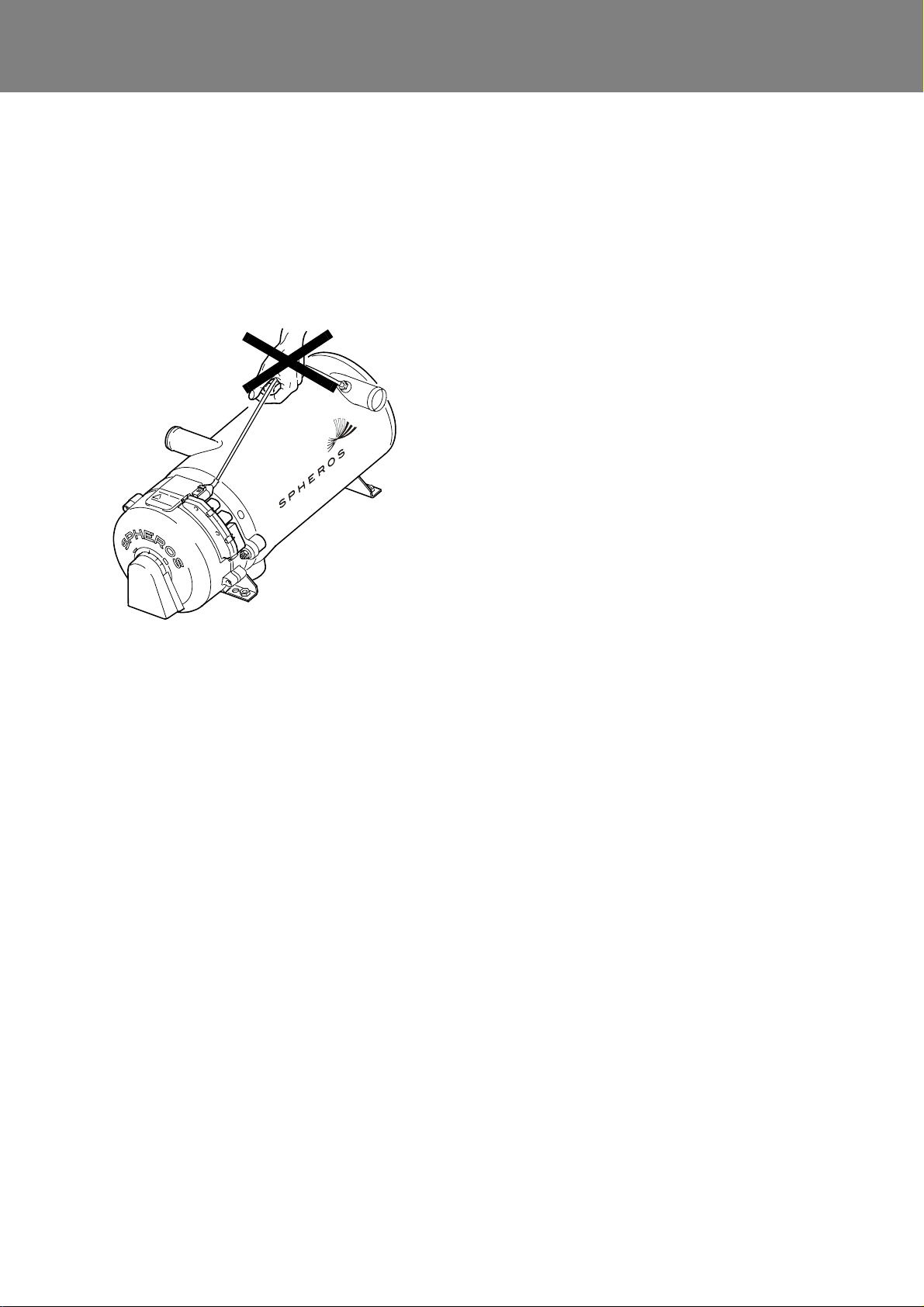
1.6.2 Other safety information
1.6.2.1 Temperature sensors
ATTENTION:
The temperature sensors cable may not be mechanically stressed (pull on the cable, carry the heater at
the cable etc.).
1.7 Suggestions for improvement and
change
Please direct any complaints, improvement or modification suggestions regarding this manual to:
service@spheros.de
102

Thermo plus 230/300/350 2 Technical Data
2 Technical Data
Unless limiting values are defined, the technical data
should be understood with tolerances of ±10% common
for heaters at an ambient temperature of +20°C, and at
nominal voltage.
Table 201 Technical Data
Heater Thermo plus 230 Thermo plus 300 Thermo plus 350
ECE Type Approval Number E1 122R 00
Kind of construction
Heating flow (at ambient temperature of
20°C)
Fuel
Fuel consumption kg/h
Rated voltage V =
Operating voltage range V =
Rated power consumption at 24V * W
Max. permitted temperature of sucked
combustion air at < 85°C ambient temperature
Max. permitted temperature of sucked
combustion air at > 85°C ambient temperature
Permitted ambient temperature during operation
Permitted storage temperature °C
Permitted operating overpressure bar
Capacity of the heat exchanger l
Minimum water flow *** l/h
Minimum capacity of the water system l
CO
in exhaust gas at rated voltage Vol %
2
Heater dimensions (tolerance ± 3 mm) mm
Weight kg
kW
(kcal/h)
°C
°C
°C
0466 0467 0468
High pressure atomizer
23
(20 000)
Diesel / Heating oil
2.5 3.0 3.6
60 90 120
-40...+ 85 (100**)
1900 2400 2700
9.0 + 1.5
Length 540 / Width 250 / Height 222
30
(26 000)
24
20.5 ... 30
85
60
-40...+ 110
max. 2.0
1.8
25
9.5 + 1.5 9.5 + 1.5
16.8
(30 000)
35
* without circulating pump
** When operating in ambient temperatures >85°C a special Spheros wiring harness is to be used.
** Minimum water flow at coolant temperatures above 50°C
Below 50°C a lower water flow is permitted, if the occurence of vapor bubbles due to local overheating safely can be excluded.
2.1 Elektrical components
Control unit, circulating pump, solenoid valve, electronic
ignition and the digital timer are designed for 24V nominal
voltage. The burner motor supply voltage is controlled by
the control device.
NOTE:
2.2 Fuel
Suitable fuel is the diesel fuel specified by the vehicle manufacturer. Only the on the model plate of the heater
specified fuel must be used.
The following table lists the by Spheros approved fuels
and their specifications.
Circulating pumps must be assigned to the heaters
according to the flow resistance in the coolant circulation
system.
201

Thermo plus 230/300/350 2 Technical Data
Fuel Requirements
acc.
Summer diesel DIN EN 590
Winter diesel DIN EN 590
Arctic diesel and Diesel for a strong
winter climate
Bio diesel (FAME)
Paraffinic diesel fuel from synthesis
or hydrogenation (HVO)
Further information on approved fuels contains the TI
*
(Technical Information) Fuels.
It can be found on the Spheros homepage under Service/Technical Updates/Heating systems.
In case of air temperatures below 0°C a commercial available winter Diesel fuel must be used.
The usage of flow improvers respectively additives is permitted. There are no negative influences due to additives
known.
While using the fuels, their operating limits must be
considered and if necessary, suitable measures
(nozzle preheating, electrical heated filter) should be
applied.
If fuel is supplied from the vehicle tank, follow the
vehicle manufacturer’s instructions on additives.
*
*
ATTENTION:
DIN EN 590
DIN EN 12214
DIN EN 15940
202
Thermo plus 230/300/350 3 Assemblies and components
1
2
4
5
6
7
8
9
10
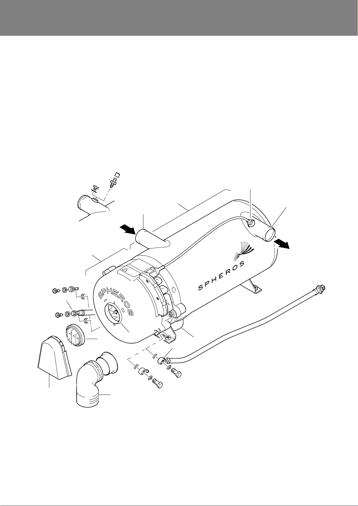
1 Burner head
2 Coolant, intake
3 Temperature sensors
4 Coolant, outlet
5 Heat exchanger
6 Exhaust outlet
7 Fuel, return
8 Combustion air, intake
Version for
additional sensor
11
9 Fuel, supply
10 Splashguard
(grid alternative)
11 Grid
12 Intake air elbow
incl. adapter
(grid alternative)
12
3
3 Description of assemblies and
components
The heaters Spheros Thermo plus 230, plus 300 and
plus 350 are used in conjunction with the vehicle heating
system
– to heat the passenger compartment
– to defrost the windows
– to preheat water-cooled vehicle engines.
The water heater operates independently from the vehicle
engine and is connected to the cooling system, the fuel
system and the electrical system of the vehicle. It is bolted
down to the vehicle chassis or is secured using an additional cross beam.
Heat is generated by combustion of liquid fuels. Via the
heat exchanger of the heater, the heat is dissipated to a
coolant circuit. The adaptation to the changing demand of
heat is reached by intermittent operation (intermittend
mode).
The control device controls on the basis of the signals of
a temperature sensor the on and off switching of the
burner.
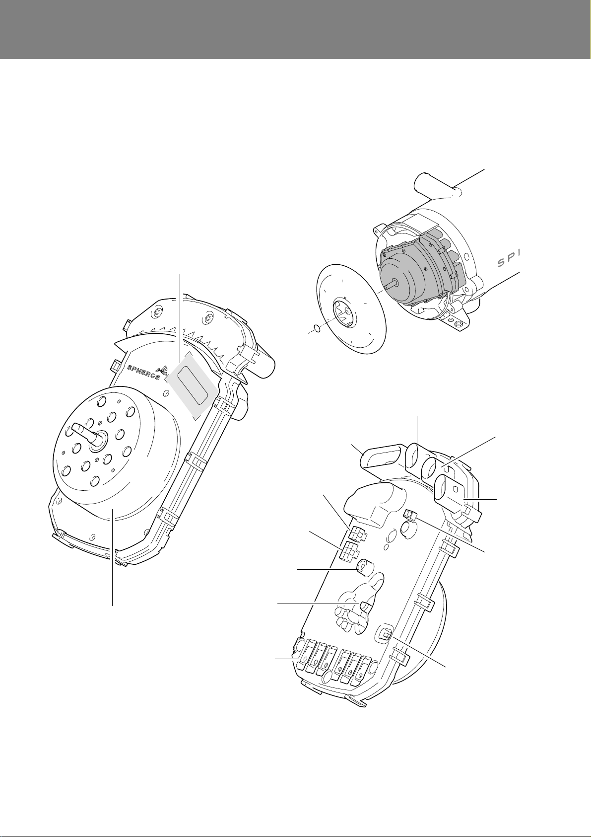
Fig. 301 Heater overview
301
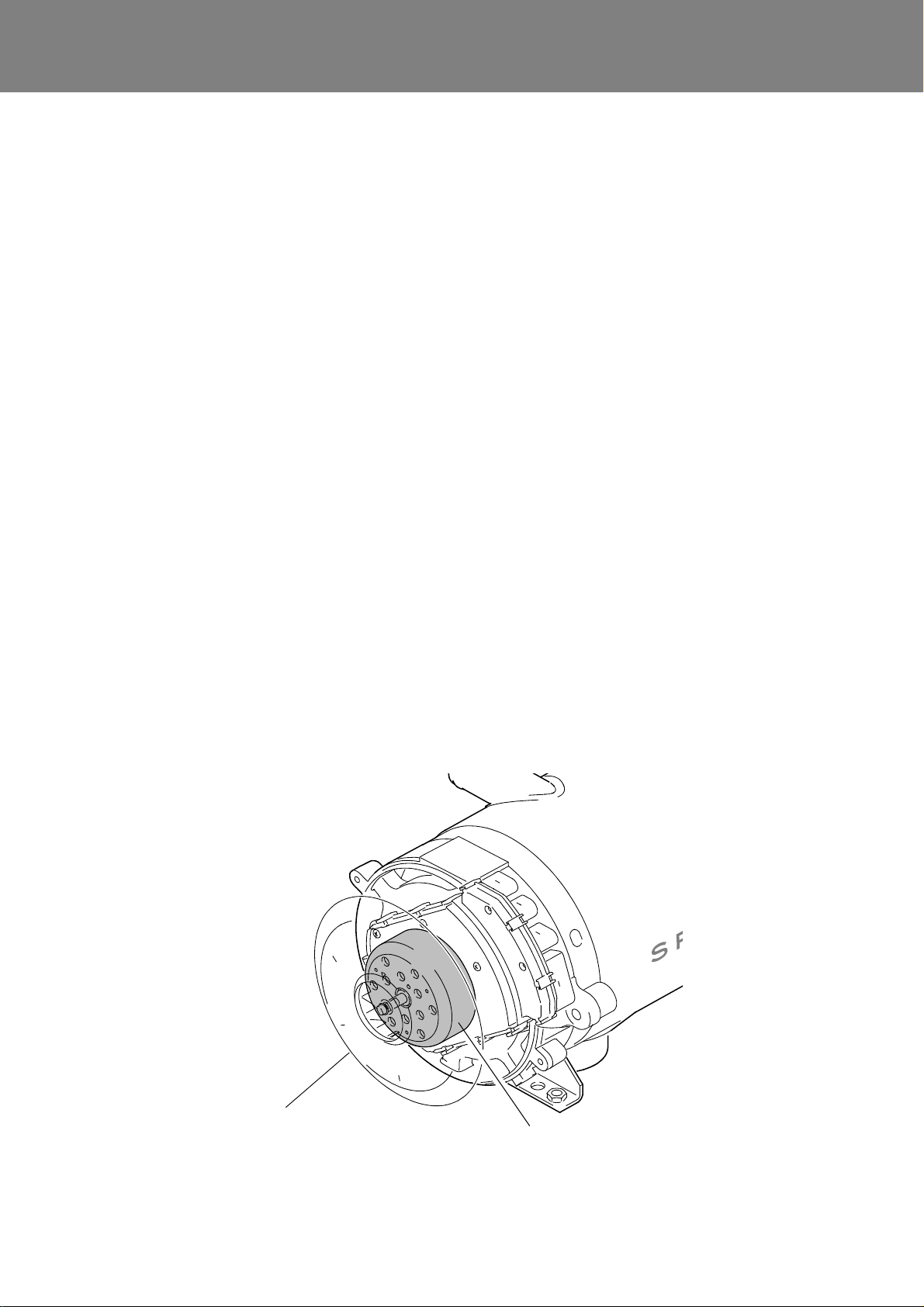
Thermo plus 230/300/350 3 Assemblies and components
Fan wheel
Burner motor
(displayed transparently)
The heaters of the Thermo plus series basically consist of
the main components:
• burner head
• combustion chamber
• heat exchanger
External in the vehicle a circulation pump is installed or in
case of compact device directly on the heater.
3.1 Burner head
The burner head consists of the components
• combustion air fan
• control device with burner motor and flame guard
• fuel pump with solenoid valve and atomizer nozzle
• electronic ignition unit with ignition electrodes
• nozzle preheater (optional)
• disc with sight window
3.1.1 Combustion air fan
The combustion air fan (Fig. 302) transports the air
required for combustion from the combustion air intake to
the combustion chamber.
The combustion air fan consists of the burner motor at the
control device and the fan wheel. Air is drawn in through
the air intake opening in the hood.
This air intake opening is equipped with a splashguard, a
protective grid or an intake air elbow (see Fig. 301).
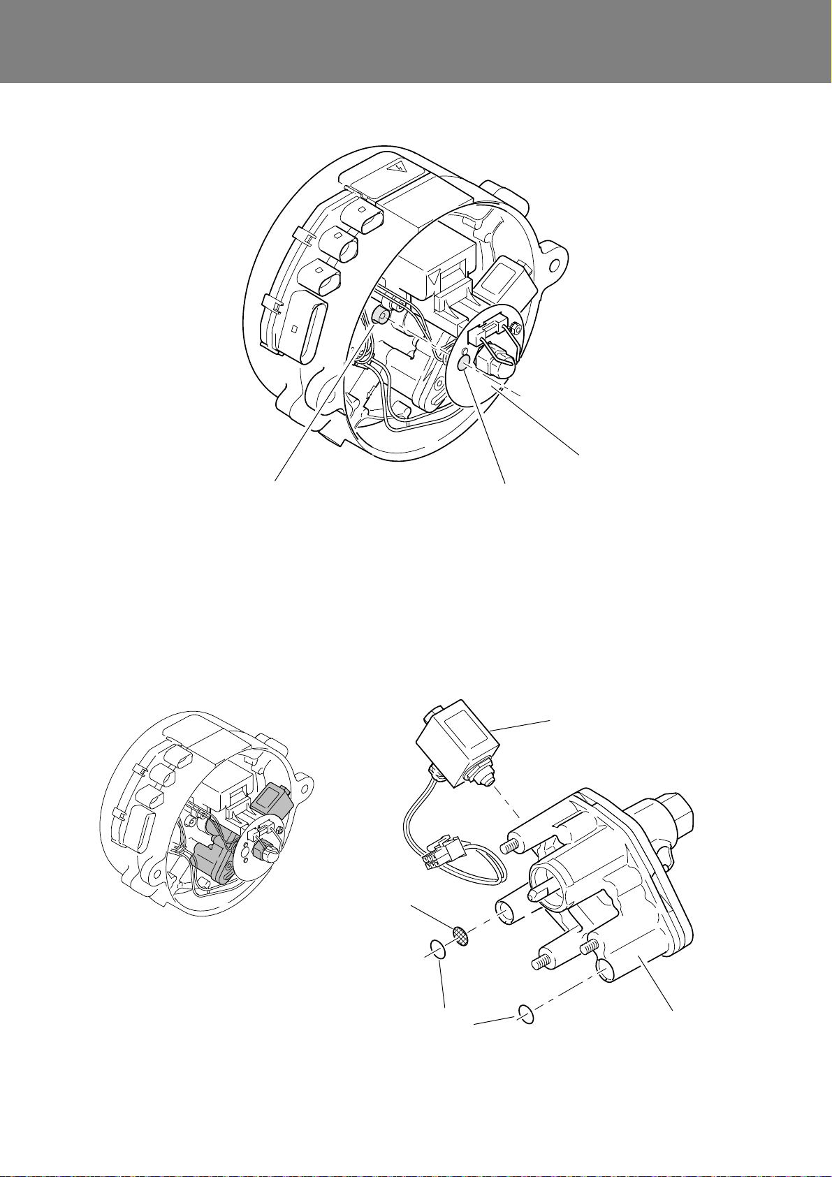
3.1.2 Control device
The control device (Fig. 303) ensures the operating
sequence and burner operation monitoring. It constitutes
a unit with the burner motor.
The control device is mounted onto the front of the burner
housing, under the hood. It protrudes with four external
electric ports out the heater:
• Port C - power/control,
• Port P - circulating pump,
• Port T - temperature sensors and
• Port G - diagnosis interface
Internally the control device provides the ports
• connector V - nozzle preheater,
• connector M - solenoid valve, and
• connector Z - electronic ignition unit.
3.1.2.1 Burner motor
The control device constitutes a unit with the brushless
EC burner motor which is installed at the burner housing.
This arangement allows its direct power supply via the
control device board. The speed measurement is done by
a Hall sensor module.
The shaft of the external rotor motor protrudes through the
control device. To the forward end the fan wheel is installed and on the backside of the control device via a coupling the fuel pump is driven.
The speed of the burner motor is controlled depending on
the operating status by the control device.
Fig. 302 Combustion air fan
302
Thermo plus 230/300/350 3 Assemblies and components
Flameguard
Motor shaft
burner motor
Heat transition
Port C
power supply
Port Z
electronic
Port M
solenoid
Port P
circulating pump
Diagnostic
Interface
Port T
temperature
sensors
Burner motor
ignition unit
valve
Model plate with Id.no.
control device/motor
Port G
Diagnosis
Port V
nozzle block
preheating
Ground terminal
to housing
surfaces to
housing
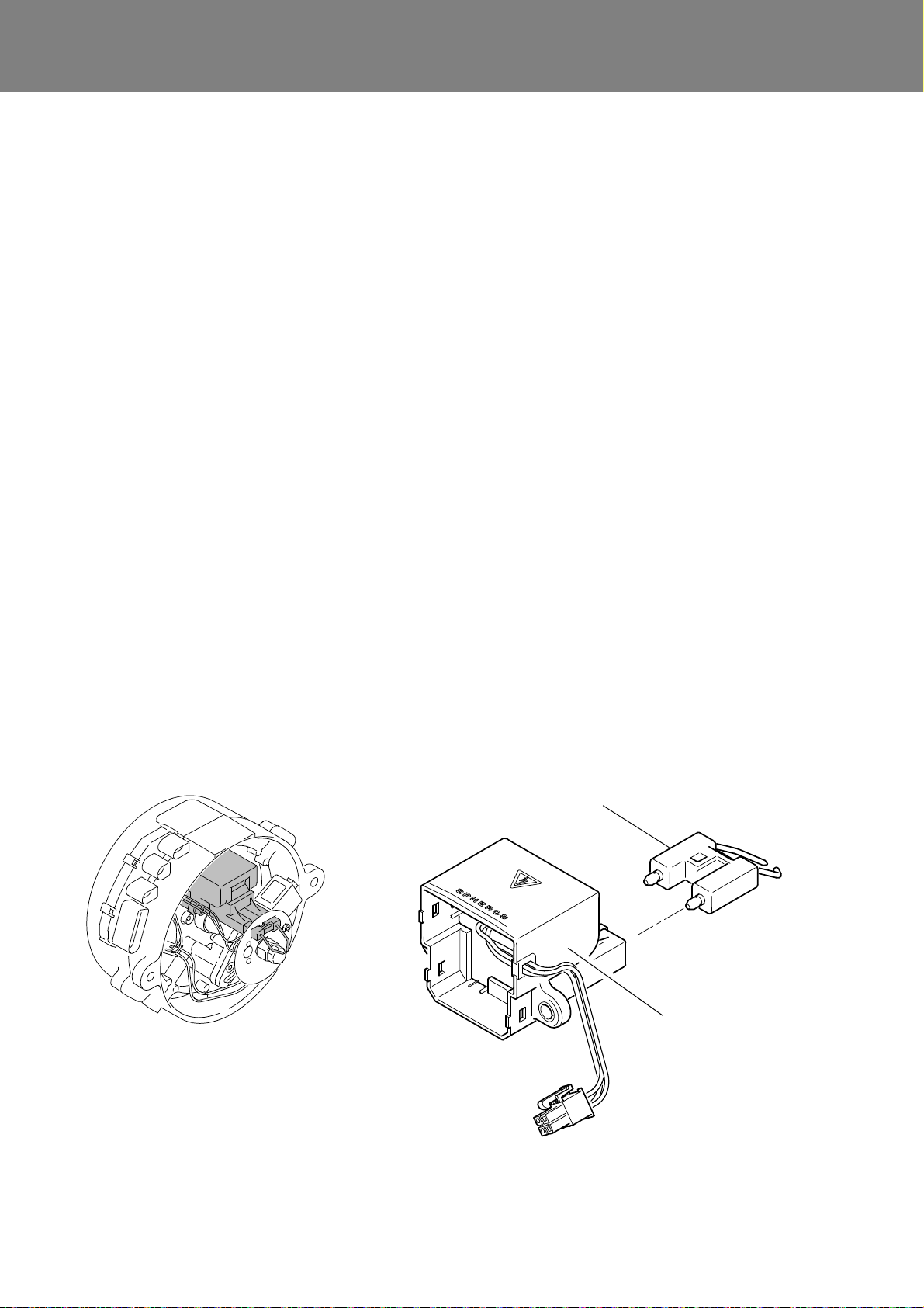
3.1.2.2 Flameguard
The flameguard (see Fig. 304) is integrated in the control
device.
The flameguard monitors the combustion flame condition
during heater operation.
The flame guard is a photo transistor that changes its
resistance depending on the incident light.
Fig. 303 Control device SG1589
303
Thermo plus 230/300/350 3 Assemblies and components
Disc
Sight window
Flameguard
Fuel pump
Solenoid valve
Screen
O-ring
Burner head
Fig. 304 Flameguard
3.1.3 Fuel pump
The fuel pump is responsible for fuel supply. (Fig. 305).
The pump is driven by the burner motor via a coupling.
Fuel is compressed in the fuel pump to approx. 10 bar and
atomized by the atomiser nozzle.
The solenoid valve installed at the fuel pump opens and
closes the fuel supply to the atomizer nozzle.
For all three heating capacity classes the same fuel pump
is installed.
Fig. 305 Fuel pump with solenoid valve
304
Thermo plus 230/300/350 3 Assemblies and components
Ignition electrodes
Burner head
Electronic ignition unit
The fuel pump can be used in dual-line operation only
(fuel supply and return line).
If the heater is operated with
– a long fuel supply line
– check valves in the fuel supply and return line
– a fuel filter in the fuel supply line
the fuel supply line must be filled prior to first heater startup (see 8.15).
3.1.4 Electronic ignition unit with ignition
electrodes
The electronic ignition unit (Fig. 306) induces the high
voltage required for ignition of the fuel-air mixture. Ignition
is triggered by a high voltage spark, which is initiated on
the ignition electrodes.
3.1.5 Nozzle block preheater
In case of very low temperatures fuel may exhibit severely
modified viscosity. Due to insufficient fuel atomization
functional heater malfunctions may occur.
Depending on the fuel used, these temperatures vary.
When used in cold regions or if fuels different from diesel
fuel are used, we recommend the use of a nozzle block
preheater (Fig. 307).
The nozzle block preheater consists of a heating element
and a thermostat. It is supplied with electricity via the fuse
of the circulating pump and works only when the circulating pump output is error-free.
At a temperature of < 5°C the heating element heats the
nozzle holder and thus, fuel and atomizer nozzle. Fuel
viscosity is reduced and atomization improved.
The heating time depends on the temperature of intake air
and the heat reflection from the combustion space. Above
8 °C the thermostat switches off. The control device
defines the preheating time depending on the temperature when starting.
The use of the nozzle block preheater is optional. The
retrofitting can be done without control device modification.
NOTE:
The nozzle block preheater is supplied with electricity via
the fuse of the circulating pump and works only when the
circulating pump output is error-free.
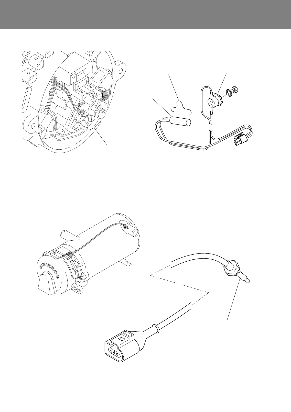
3.1.6 Temperature sensors with water
temperature sensor and integrated
overheating protection
The water temperature sensor (Fig. 308) captures the
coolant temperature at the heat exchanger outlet as
electrical resistance.
This signal is transmitted to the control device, where it is
processed.
The overheating protection integrated into the temperature sensor is responsible for temperature limitation.
Overheating protection prevents inadmissibly high heater
operating temperatures.
At a temperature greater than 135°C heater deactivation
and interlocking is initiated.
Fig. 306 Electronic ignition unit with ignition electrodes
305
Thermo plus 230/300/350 3 Assemblies and components
Thermostat
Heating element
Burner head
NOTE:
The disc is displayed
transparently.
Retaining clamp
Water temperature sensor
with integrated overheat
protection
Fig. 307 Nozzle block preheater
Fig. 308 Temperature sensors
306
Thermo plus 230/300/350 3 Assemblies and components
Coolant inlet
Coolant outlet
Exhaust outlet
Combustion chamber
Welding seam
Swirl plate
3.2 Heat exchanger
The heat exchanger (Fig. 309) transfers the heat generated by combustion to the coolant circulation system.
Depending on the system integration a heat exchanger
with or without thread in the coolant inlet socket can be
installed.
NOTE:
In the heaters are used different combustion chambers
depending on the heating capacity class.
Fig. 311 Combustion chamber
Fig. 309 Heat exchanger
3.3 Combustion chamber
The combustion chamber (Fig. 311) is used for generation
and combustion of the fuel air mixture. The generated
exhaust gas heats the coolant flowing through the heat
exchanger.
3.4 Circulating pump
The externally arranged circulating pump ensures coolant
transport within the vehicle and/or heater circulation
system.
Depending on the application, the circulating pump is switched on via the control device or directly via the vehicle
electrical system and operated during the entire heater
operation duration.
Further information on the installation and operation of the
circulating pump is contained in the Thermo plus Installation Instructions.
All service information regarding your Spheros circulating
pump(s) can be found under www.spheros.eu/products/
pumps.html.
3.5 Fuel filter
As an option a heated fuel filter is available (see
www.spheros.eu/service/spare parts and accessories).
The integrated filter heating is switched on at a fuel temperature of ≤ 0.5 ± 2.5 °C and off at ≥ 5.5 ± 2.5 °C by a
temperature switch.
When the heater is operated at low temperatures,
depending on fuel used a heated fuel filter must be
installed. See TI.
Fig. 310
307

Thermo plus 230/300/350 4 Heater functions
4 Heater functions
4.1 General heater functionality
description
The heater principle is based on a high-pressure atomizer
burner and is monitored by an integrated control unit.
The burner motor powers the fan and the fuel pump. The
fuel pump is coupled to the motor using a plastic coupling.
The fan produces the required combustion air, the combustion air volume is impacted by the burner motor speed.
The speed is read and monitored by a Hall sensor.
The speed required for the CO
during first calibration at Spheros and is stored in the
control unit.
In a maintenance event the workshop can adjust the CO
setting using the STT diagnosis (Spheros-Thermo-TestDiagnosis) (siehe 4.3).
The fuel pressure is generated in the fuel pump and
reduced to the required pressure using a pressure limiting
valve.
A solenoid valve releases the fuel via the atomizer nozzle
for combustion in the combustion chamber.
As an option, the fuel pump can be equipped with a nozzle
block preheater. The nozzle block preheater heats the
content is determined
2
nozzle holder with the atomizer nozzle at low temperatures, and thus the fuel. The fuel air mixture is ignited in
the combustion chamber via a high-voltage ignition spark.
The flame is monitored by a flame detector integrated into
the control device.
Depending on the equipment, the heater is switched on
and off using a
• digital timer
•switch
• or climate control.
During heating operation the burner is automatically switched on and off. For control a temperature sensor is
installed in the coolant outlet of the heat exchanger.
The heater is switched on, when the temperature falls
short of a lower temperature threshold, and is switched
off, if the upper temperature threshold is reached (see
2
Table 401).
The switching thresholds depend on the operation mode
of the heater and are programmed into the control device.
An operation indicator is available for monitoring the
operation status of the heater. A flame indication can be
optionally installed.
The operation indicator is also used to output error
messages via flash code.
Table 401 Water Temperature Control Thresholds (standard data set)
Heater Aux. heating
(terminal 61)
on off (CI) on off (CI) on off (CI)
Thermo plus 230
Thermo plus 300
Thermo plus 350
CI: Control idle
on/off : lower/upper threshold
Aux. heating: Heater is operating, engine is opera-
ting
Parking heating: Heater is operating, engine is off
Economy setting: Control temperature is on a lower level
NOTE:
Auxiliary heating has priority over the economy setting!
72 82 67 77 55 70
Parking heating Econ. setting
401
Thermo plus 230/300/350 4 Heater functions
Signals
Main switch off on off
UPFA
Econ. mode
Terminal 61
off (parking heating) on (aux. heating)
Coolant temperature T > T_min T < T_min T >= T_max T >= T_max
Flame
generation
Flame
generation
Flame
generation
Actuators
Operation indicator
Flame indicator
Comb. air motor
Circulating pump
Electronic ignition unit
Solenoid valve
Nozzle block preheater
Time in s 0..128 12 1 15 ... 30 90 0..128 12 1 15 ... 30 90 0..128 12 1 15 ... 30 90
Status
Look for
Nozzle block preheater
Initial cycle with light check
Pre-ignition
Ignition
Purge cycle 1 with safety period
Purge cycle 2
Nozzle block preheater
Initial cycle with light check
Pre-ignition
Ignition
Purge cycle 1 with safety period
Purge cycle 2
Nozzle block preheater
Initial cycle with light check
Pre-ignition
Ignition
Purge cycle 1 with safety period
Purge cycle 2
OFF Standby Start Heating Purge
cycle
Standby Start Heatin g Purge
cycle
Standby Start H eating Purge
cycle
OFF
Parking heating Aux. heating Parking heating
On On or Off
4.2 Operational heater sequence
Fig. 401 Operational sequence
4.2.1 Switching on and start
With optional nozzle block preheater:
With activated circulating pump the bimetal at the nozzle
the control unit starts controlled operation and checks the
coolant temperature.
If the coolant temperature is below the lower temperature
threshold, the initial cycle starts.Combustion air fan and
circulating pump are switched on. The initial cycle is used
to flush the combustion chamber.
In the start phase until to the pre-ignition the in the control
When switched on, the operating display is illuminated,
device integrated flameguard must continuously detect
„dark“, otherwise it comes to a fault lock-out and the
heater changes into the standby.
After approx. 12 seconds (initial cycle time) the high-voltage spark is ignited. Approx. 1 second later the solenoid
valve in the fuel pump is opened.
The fuel injected via the atomizer nozzle and mixed with
the air of the combustion air fan, is ignited by the ignition
spark and burned in the combustion chamber.
The monitoring of the flame is done by the flame guard.
A few seconds after a flame is detected, the control device
switches the electronic ignition unit off. Until then the
flame is stabilized and the heater is not yet in heating
mode.
block preheater controls its operation. When the ambient
temperature is less than 5 °C it is turned on. Not timedependent and not limited.
Starting from a temperature <5 °C, the duration of the
nozzle block preheating is prolonged, depending on the
determined temperature. The maximum duty cycle is
limited to 140 seconds. The further procedure is as
described.
4.2.2 Heating operation
After the flame is stabilised, the heater is in controlled
(normal) operation.
Depending on the coolant temperature, the coolant
temperature is maintained at one level by switching the
burner alternately on and off.
Once the upper switching threshold is exceeded, heating
operation is finished and the purge cycle initiated.
The solenoid valve is closed, the flame expires, however
the combustion air fan and the circulating pump continue
running.
402

Thermo plus 230/300/350 4 Heater functions
The purge cycle ends approx. after 120 seconds. The
combustion air fan is switched off.
The heater is in a controlled break.
The operation indicator is on.
Once the temperature falls short of the lower switching
threshold, the heater restarts burner operation. It runs
through the same sequence as the switching-on
sequence.
4.2.2.1 Auxiliary heating mode and parking heating
mode
From the terminal D+/+61 the control device receives the
information either the vehicle engine is running or not.
If the engine is running the heater is in the auxiliary
heating mode.
The switching thresholds are higher than in the parking
mode with the engine not running.
In the parking heating operation an economy mode may
be activated.
4.2.2.2 Economy circuit
If the economy circuit is activated (economy mode) the
controlled temperatures inthe heating system are maintained at a low temperature level. The lower and upper
switching threshold are reduced.
Due to lower radiation loss the fuel consumption can be
reduced for a lower heat demand (e.g. warmer mode).
The heater burner output is not reduced.
n auxiliary heating mode (signal from terminal D+/+61)
saving mode is automatically deactivated.
4.2.2.3 Gradient evaluation
always achieved.
In order to achieve the minimum combustion period, the
lower switching threshold is variably adjusted by the
control device.
This process is also called hysteresis adaptation and is
applied in parking heating operation as well as auxiliary
heating operation.
If the combustion period falls short of the minimum
combustion period of 120 seconds, the lower switching
value is lowered by 1K for the following combustion
process. The upper switching threshold remains as is.
This can be repeated until the minimum combustion
period is reached or the lower switching threshold is
reduced by 5K.
A further lowering is not possible.
Following a combustion process, where the required
minimum combustion period was reached, the lower switching threshold is raised in steps of 1 K, max. up to the
initial level.
4.2.3 Switching off
Switching the heater off ends the combustion process.
The operation indicator goes out and and the purge cycle
is initiated.
The solenoid valve closes, the flame expires, the combustion air fan and the circulating pump continue running.
The purge cycle ends approx. after 120 seconds. The
combustion air fan is switched off.
If a malfunction occurs during purge cycle (e.g. flame
detection), the purge cycle may be shorter than 120
seconds.
During purge cycle it is permitted to switch the heater back
on. The burner will restart after a purge cycle time of 30
seconds and subsequent initial cycle time.
In case of low coolant flow or poor coolant circuit venting
the temperature quickly increases in heating operation.
The control device recognises the quick temperature
increase and automatically sets the upper switching threshold to a lower value.
The quicker the temperature increases, the lower the switching threshold for starting the controlled break is set.
In addition, the burner is also switched back on again after
the controlled break at a lower switching threshold.
This prevents residual heat triggering the overheating
protection.
4.2.2.4 Minimum combustion period
NOTE:
Frequent burning time under 120 seconds may result in
soot build and increased smoke formation.
A minimum burner combustion period of 120 second is
targeted.
For ambient and operating conditions this target is not
4.3 Diagnosis interface and (Spheros
Thermo Test) STT diagnosis
Heaters of the Thermo S series support diagnosis capabilities. Using the STT diagnosis adapter, STT diagnosis
and a PC, the heaters in a vehicle can be checked.
Information on the hook-up of the heater to the diagnosis
and its usage can be found in the STT Operation Instructions which are supplied with the device.
The Operation Instructions are also available for download on the Sheros homepage in the area Service/
Technical Documents/Accessories.
NOTE:
For protection against moisture and contamination ensure
that the diagnosis interface is sealed using a dummy plug,
if not in use.
403

Thermo plus 230/300/350 4 Heater functions
4.4 Fault lock-out and heater lock-out
A distinction is made between fault lock-out and heater
lock-out.
The lock-outs protect the heater and the surrounding
vehicle assemblies against sequence errors after a failure
or a malfunction of individual heater components.
In a heater lock-out safety-related components are
affected by the failure or malfunction. It may only be
released by Spheros trained personnel after eliminating
the cause.
Each fault lock-out and heater lock-out is stored in the
control device.
4.5 Fault lock-out
If one of the malfunctions listed below occurs, the heater
will initiate a fault shut-down, followed by a fault lock-out.
Depending on the error timing, no purge cycle or a 120
seconds purge cycle will be executed.
Flash impulses are outputted via the operation indicator.
In case of several sequential fault lock-outs a heater lockout is initiated (see 5.4).
NOTE:
If the circulating pump is externally actuated it will continue operating, if it is not affected itself.
30 V within a duration of 6 seconds (purge cycle only,
no fault lock-out).
4.5.2 Malfunctions during heater operation
In case of malfunctions during heater operation, a 120
seconds purge cycle will be executed first. Subsequently
the heater status is switched to fault lock-out.
Malfunction criteria:
• Circulating pump - short circuit and/or interruption
• Water temperature greater than the upper switching
threshold
• Temperature sensor delivers unacceptable tempe-
rature values.
• Heater operation outside the permissible temperature
range.
• Burner motor speed signal faulty.
• Flame interruption (combustion interruption for longer
than 15 seconds).
• Voltage falls short of the low voltage threshold of
approx. 20.5 V within a duration of 20 seconds after a
heating request.
• Voltage exceeds the high voltage threshold of approx.
30 V within a duration of 6 seconds (purge cycle is
applied only, but no fault lock-out).
• Control device malfunction
4.5.3 Malfunctions during purge cycle
In case of several sequential fault lock-outs a heater lockout is initiated (see 4.6).
4.5.1 Malfunctions during switching-on and
start procedure
If malfunctions occur during switching-on or during the
start process prior to ignition, the heater will be switched
off without purge cycle.
The heater is in fault lock-out.The motor stops immediately or does not start.
Malfunction criteria:
• Short circuit and/or interruption of electrical
components:
– Circulating pump
– Electronic ignition unit
– Optional nozzle block preheater
• Flame or extraneous light detection by the flameguard
prior to opening of the solenoid valve.
• No start: No flame detection within 15 seconds after
opening the solenoid valve.
• Temperature sensor delivers unacceptable
temperature values.
• Burner motor speed signal faulty.
• Voltage falls short of the low voltage threshold of
approx. 20.5 V within a duration of 20 seconds after a
heating request.
• Voltage exceeds the high voltage threshold of approx.
After the purge cycle the heater goes into the fault lockout.
Malfunction criteria:
• Circulating pump - short circuit and/or interruption
• Heater operation outside the permissible temperature
range.
• Burner motor speed signal faulty.
• Voltage falls short of the low voltage threshold of
approx. 20.5 V within a duration of 20 seconds after a
heating request.
• Voltage exceeds the high voltage threshold of approx.
30 V within a duration of 6 seconds (purge cycle is
applied only, but no fault lock-out).
• Control device malfunction
404
 Loading...