

HEATING SYSTEMS
THERMO DC 200
Bus
Installation and
operating instructions
Rev. 01/2017
Id.No. 11118910A
Thermo DC 200
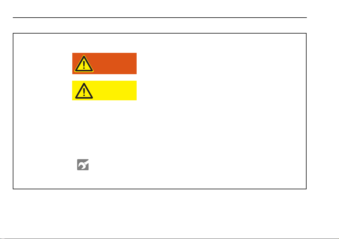
Highlighted words like Warning!, Caution!, ATTENTION: and NOTE: in these Installation and operating instructions signify the following precautions:
Other symbols used in these Installation and operating instructions:
This caption is used to indicate possible severe injuries
or fatal accidents if instructions or procedures are carried out incorrectly or entirely disregarded.
This caption is used to indicate possible minor injuries
if instructions or procedures are carried out incorrectly
or entirely disregarded.
ATTENTION:
This caption points to actions which may cause material
damage.
NOTE:
This caption is used to draw attention to an important
feature.
Symbol
tightening
torque
Identifies in graphics parts (e.g. nuts, bolts) that are to
be mounted with a specific tightening torque. The torque values are shown at the symbol and are binding.
Warning!
Caution!
NOTE: Subject to modification. In multilingual versions the German language is binding. The latest version of this document is provided for download
on www.spheros.de.
II

Thermo DC 200
Table of Contents
1 Statutory regulations governing installation 1
1.1 Statutory regulations governing installation 1
1.2 Model plate 2
2 Safety regulations 3
3 Use / Version 4
3.1 Installation example 5
4 Operating and maintenance instructions 6
5 Installation 7
5.1 Grounding, additional protective equipotential
bonding 7
5.2 690 VDC supply line 7
5.3 Overcurrent protection / insulation
monitoring device 11
5.4 External power supply hook-up 12
5.5 Testing 12
6 Maintenance 13
7 Faults, troubleshooting, repairs 14
8 Control elements 15
8.1 Switch or relay 15
8.2 Pre-selection timer 16
8.3 Activation via mains power 21
8.4 Operation indicator 21
9 Circulation pump 22
10 Switching thresholds 22
11 Installation of the heater - fitting of important
assemblies 23
11.1 Installation 23
11.2 Connection to the vehicle's cooling system 26
11.3 Installation of the circulation pump 27
11.4 Tightening torques 28
12 Technical data 29
III

Thermo DC 200
IV

Thermo DC 200 Statutory regulations governing installation
1 Statutory regulations governing installation
1.1. Statutory regulations governing installation
For the heater exists a type approval according to the ECE Regulations
R10 (EMC) No. 04 6641 and
R122 (Heater) No. 00 0377.
Installation is governed above all by the provisions in Annex 7 of the
ECE Regulation R122. In addition, the electrical safety requirements of
ECE Regulation R100 are to be observed.
NOTE: The provisions of these Regulations are binding within the
territory governed by ECE Regulations and should similarly be observed in countries without specific regulations!
Extract from ECE Regulation R122, Annex 7:
4 The heater must have a manufacturer’s label showing the manufacturer’s name, the model number and type together with its rated
output in kilowatts. The operating voltage and the electric power must
also be stated.
7.1 A clearly visible tell-tale in the operator’s field of view shall inform
when the heater is switched on or off.
Extract from ECE Regulation R122, Part I:
5.3 Installation Requirements for Combustion Heaters and
Electrical Heaters into Vehicles
5.3.1 Scope
5.3.1.1 Subject to paragraph 5.3.1.2., heaters shall be installed
according to the requirements of paragraph 5.3.
5.3.2 Positioning of combustion heater
5.3.2.1 Body sections and any other components in the vicinity of the
heater must be protected from excessive heat and the possibility of fuel
or oil contamination.
5.3.2.2 The heater shall not constitute a risk of fire, even in the case of
overheating. This requirement shall be deemed to be met if the installation ensures an adequate distance to all parts and suitable ventilation,
by the use of fire resistant materials or by the use of heat shields.
5.3.2.3 In the case of M2 and M3 vehicles, the heater must not be positioned in the passenger compartment. However, an installation in an
effectively sealed envelope which also complies with the conditions in
paragraph 5.3.2.2 may be used.
5.3.2.4 The label referred to in Annex 7, paragraph 4 or a duplicate,
must be positioned so that it can be easily read when the heater is installed in the vehicle.
5.3.2.5 Every reasonable precaution should be taken in positioning the
heater to minimize the risk of injury and damage to personal property.
5.3.6 Heating air inlet
not applicable
5.3.7 Heating air outlet
not applicable
1
Statutory regulations governing installation Thermo DC 200
Danger to life and health!
Warning!
Thermo DC
0Hz/30A
690 VDC / 20kW
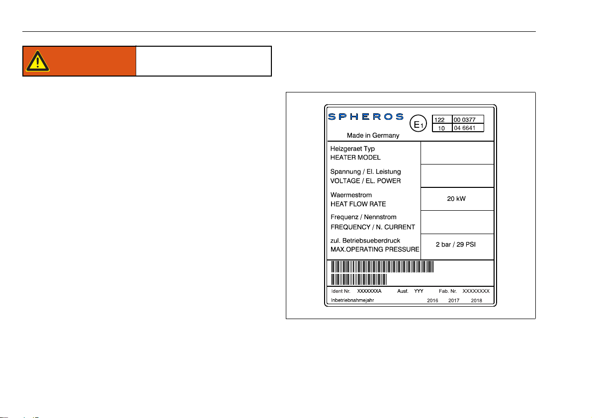
1.2. Model plate
The model plate must be protected from damage and must be clearly
legible when the heater is installed (otherwise a duplicate model plate
must be used).
Applicable local regulations, laws and standards for electrical installations, in particular the provisions of ECE Regulation R100 are
to be observed by the vehicle manufacturer and should be appropriately implemented.
ATTENTION:
Failure to follow the installation instructions and the notes contained therein will lead to all liability being refused by Spheros. The
same applies if repairs are carried out incorrectly or with the use of
parts other than genuine spare parts. This results to the invalidation of the type approval of the heater.
2
Figure 1: Model plate (example)
NOTE: The year of the initial operation must be durably marked by
removing the year numbers that are not applicable.
Thermo DC 200 Safety regulations
High voltage! Danger to life!
Warning!
2 Safety regulations
NOTE:
The provisions of these Regulations are binding within the territory
governed by DGUV Regulations and should similarly be observed in
Installation, maintenance and repairs may only be carried out when
the vehicle's engine is not running and the high voltage supply is
switched off.
Before starting the work at the heater, it is to make voltageless acc.
to DIN VDE 0105-100 and this state must be ensured for the duration of the work.
In particular, the following safety precautions must be observed:
– switch off the power supply to the heater
– ensure it cannot be switched on again
– verify, system is voltage-free, all poles
– ground and short circuit
– cover or block neighbouring parts under voltage
Electrical cables and operating elements of the heater must be arranged in the vehicle in such a way that their functioning is faultless under normal operating conditions and cannot be hampered.
Work at electrical equipment may only be started if protective
measures against electric shock, short circuits and arcing faults
have been carried out.
Electrical work may only be performed by a qualified electrician for
HV systems in motor vehicles, craftsman, activity with repetitive
character. Training acc. to DGUV 200-005 (previously BGI 8686).
countries without specific regulations.
3
Use / Version Thermo DC 200
Danger to life and health!
Warning!
Hot surfaces!
Caution!
3 Use / Version
The fully electrical water heater Thermo DC operates independently of
the vehicle engine and is connected to the vehicle’s cooling and
electrical systems.
The electrical heater can be used in a depot for pre-heating purposes.
For this it is connected stably to the depot 690 VDC power supply.
Further more the heater also can be used in electric driven buses or
hybrid buses where a 690 VDC power supply is provided, in association
with the vehicle‘s own heating system:
– to heat the passenger cabin,
– to defrost the vehicle windows,
– for pre-heating.
The heaters are approved for horizontal installation only (see Figure 18).
The heater Thermo DC is approved for heating the diesel engine
and the passenger cabin of buses, but not for use in vehicles
subjected to the Directive 94/55/EC (ADR, TRS).
General Information / Safety
Check the information given on your heaters rating plate and compare
this with your mains voltage!
In addition to the statutory regulations the specific connection conditions
of local electricity companies are to be observed.
No alterations to the electrical installation may be undertaken.
The installation and commissioning may only be carried out by a qualified electrician.
Only have any work on the appliance carried out by a specialist
company or a qualified person.
The installation instructions are to be considered.
Under no circumstances touch the heat exchanger and the water
hoses during operation, in particular when they are overheated due
to lack of water.
Ensure an adequate distance to all surrounding parts and a sufficient
ventilation during installation.
Alternately use fire resistant materials or heat shields (see Statutory
Regulations governing installation, para. 5.3.2.2).
4
Thermo DC 200 Use / Version
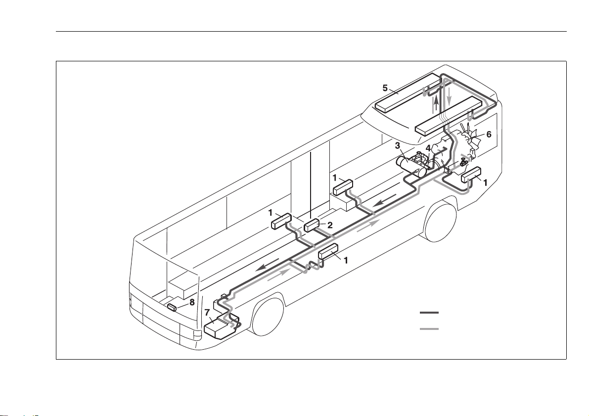
1 Wall heater with blower
2 Heat exchanger at entry
3 Heater
4 Circulating pump
5 Roof heat exchanger
6 Vehicle engine
7 Driver’s seat heating system
8 Control panel
Water heating circuit – wall heater and roof duct heating system
Supply
Return
3.1. Installation example
Figure 2: Installation example for the heater
5

Operating and maintenance instructions Thermo DC 200
4 Operating and maintenance instructions
The Thermo DC heating appliance may not be operated at temperatures
of more than +85°C. Amount of antifreeze in the water circuit - see
technical data.
ATTENTION:
The heaters may be only used in closed vehicle systems for warming up water.
They must not be operated in the depot unattended for a longer
period. The pump operation, the water cycle and the water temperature of the vehicle should be monitored. In case of any
malfunction unplug immediately the 2-pole mains plug.
Another utilization or any utilization going beyond these ones is to
be considered as unintended use. The manufacturer/supplier shall
not be liable for damages resulting from unintended use; the user
shall bear the risk alone.
6
Thermo DC 200 Installation
5Installation
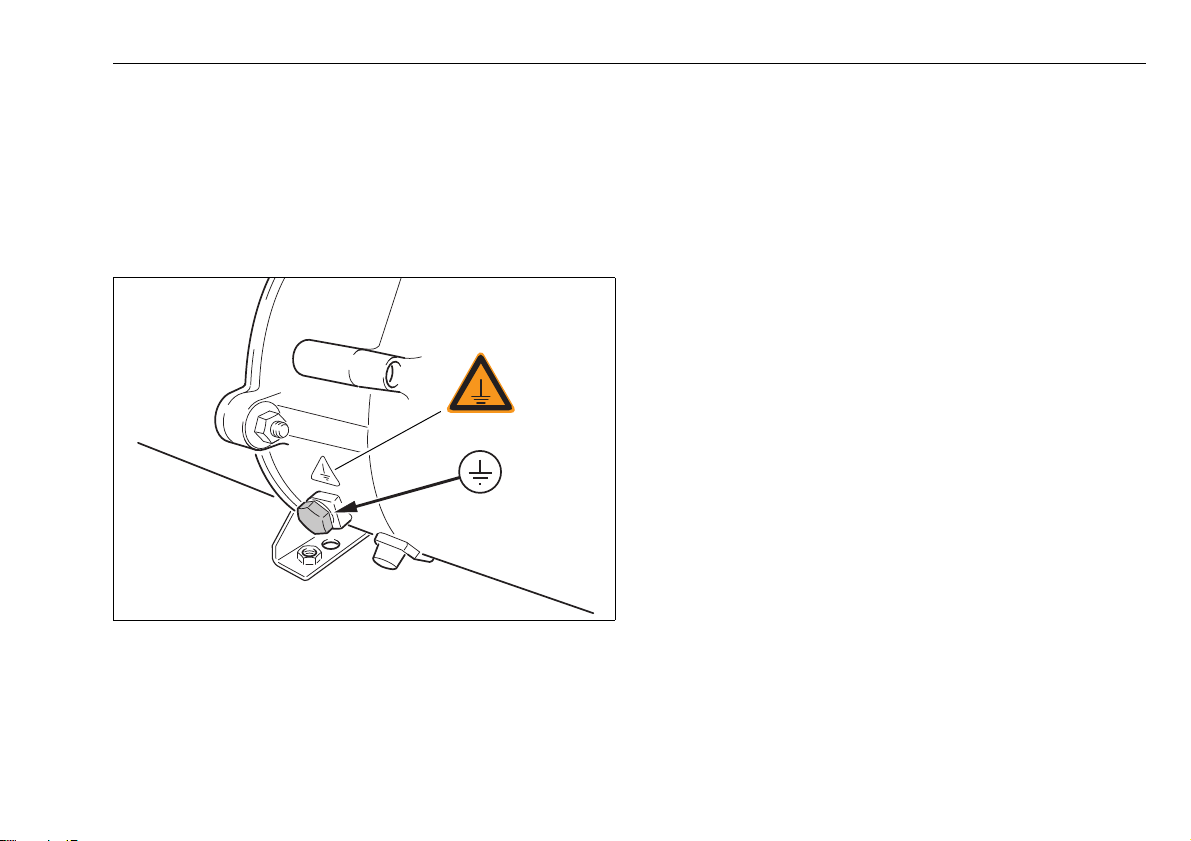
5.1. Grounding, additional protective equipotential
bonding
A grounding cable, at least 1x4 mm² Cu, should be attached to the position on the housing which is marked and provided for it. Ideally this
should be carried out with a ring cable lug for fastening with the M10x1
grounding screw (for tightening torque, refer to figure 19).
Figure 3: Grounding screw
The connecting screws on the heating appliance may only be replaced
with genuine original parts from Spheros, since these are part of the
electrical equipment and they ensure proper grounding.
5.2. 690 VDC supply line
The connection line must have a cross section of at least 2 x 4mm² Cu.
The cable cross-section must be chosen according to the power and
installed cable length. For the cable feed through, the cable gland at the
device is to be used.
Use a dedicated power circuit for the heating system.
The appliance must have a fixed connection to the DC power supply.
The heating appliance must be connected to the protective equipotential
bonding.
The connection must be carried out in accordance with the enclosed
connection diagram (see Figure 4).
7

Installation Thermo DC 200
4mm², GR, 180mm, Radox 3 GKW 12545290
0,75mm², RT,200mm, FLRY
Schütz Siemens
3TC4417/0AB4
2,5mm², RT,250mm
2,5mm², RT,250mm
QUINT/PS/ 3AC/
24DC
Radox 3 GKW 12545290
4mm², GR, 180mm,
SW
BL
BR
RT
1
1
2
2
3
4
68 ... 75 °C
125 °C
M12x1,5
1
7
283
9
4
10
5
11
6
12
14
14
-
-
-
16
13
17
18
19
20
1313
DC
OK
15
+
N
++
L1 L2 L3
GND
2
T1
4
T2
A2
24-
4mm², RT
4mm², SW
1
L1
3
L2
A1
24+
Cable colors
SW black
BL blue
BR br own
GN green
GR grey
OR orange
RT red
GNGE gr een/
yellow
690 VDC
Note the prescribed
means of protection!
- overcurrent protective device
see Section “Installation“, Figure 8
Note: Heater internal connections not shown.
Load
Contactor
Figure 4: Connecting schematic with integrated DC-DC converter (Thermo DC compact distributor board)
8

Thermo DC 200 Installation
+
-
ϑ 68.. 75°C
ϑ 125°C
1L1
+
L-
2T1
A1
24+
A2
24-
0,75mm², SW, 130mm, FLRY
15
16 19
6mm²,GR, 220mm,Radox 3GKW 12548127
1
2
3
4
RD
BR
BU
BK
1
2
10 11 12
6mm²,GR, 180mm,Radox3
GKW 1254 8127
L+
0,75mm², BK
2
1
-
DC
+
M12x1,5
0,75mm², BN
13
14
7 8 91 2 3
4 5 6
17 19
2018
6mm², RT
6mm², BL
Cable colors
SW black
BL blue
BR br own
GN green
GR grey
OR orange
RT red
GNGE gr een/
yellow
690 VDC
Note the prescribed
means of protection!
- overcurrent protective device
see Section “Installation“, Figure 8
Note: Heater internal connections not shown.
Load
Contactor
Figure 5: Connecting schematic without integrated DC-DC converter (Thermo DC compact distributor board)
9

Installation Thermo DC 200
Hook-up data:
Cord grip range: 9 - 17 mm
Use suitable tools for installation!
Contactor connections
Stripping length 11 - 13 mm
Kind of wire single wire or wire strand
or wire strand with cable end sleeves
Cable cross section 4 - 6 mm
2
Torque 3 - 4.5 Nm
250
Cable ends with end sleeves
Cord grip
Cable diameter
9 - 17 mm
Power cable
at least 2x4 mm²
10
Cable gland
for control line
(M12x1.5)
Cable gland
for power
cable (M25x1.5)
4mm², 12 mm length and
square pressure
black
red
Figure 6: Preparation of the cables and hook-up
10

Thermo DC 200 Installation
L1 und L2
Cable to the terminal
already exists
High voltage! Danger to life!
Warning!
5.3. Overcurrent protection / insulation monitoring device
ATTENTION:
The power supply circuit is to be protected through an all pole
overcurrent protection device that allows a max. current of 35A.
If the overcurrent device has been triggered, the heater is to be switched
off. It is essential that the cause is identified and the error rectified by a
qualified electrician in a specialised workshop. Only then the heating
appliance can be reconnected to the mains.
The use of overcurrent protection devices with another as specified load
ability is not permitted and will result in loss of the operating approval!
The heater must be protected on the vehicle side with all poles by
an insulation monitoring device (tripping resistance 0.5 MΩ)
against fault currents.
If the Thermo DC is monitored as a subcomponent of the BUS
system, the value can be adapted according to the applicable
statutory requirements.
The connecting schematic of the insulation monitoring device is shown
in figure 8 (for example if monitoring the stand alone device).
The specified for the fasteners torque value must be met.
Figure 7: Terminals L1 and L2
11

Installation Thermo DC 200
L1 L2
L1
L2
35A
Overcurrent
Spheros Thermo DC
Circuit breaker
protection device
all pole, 35A
DC 690 V 0Hz
after electricity
IMD 0.5 MΩ
meter
5.4. External power supply hook-up
ATTENTION:
It should be noted that with vehicles, which are to be connected to
the earthed external power supply unit via the conductive connection, a device must be present by which the galvanic connection of
the electrical earth with the ground can be made.
Before an external voltage is applied to the vehicle, the connection with
the ground must be established by this device and must be able to be
maintained until the external voltage is interrupted.
5.5. Testing
After the installation is completed, the heating appliance is to be
checked by a qualified electrician for operational safety and function!
Before the mains power is applied, close the appliance (fit the hood).
A current measurement ensures that all cartridge heaters are functioning. The current should be at 28.5A ±3A per phase.
Testing of individual cartridge heaters
Limit values for evaluation:
Insulation measurement of each connection against the housing:
R Iso > 100 MΩ
Resistance measurement between the two connection wires at 20°C
Ambient temperature: 23.3 Ω ±10%
ATTENTION:
Under no circumstances may the heaters be operated “dry“
(without water filling), since the internal construction could be
damaged!
12
Figure 8: Connection schematic

Thermo DC 200 Maintenance
High voltage! Danger to life!
Warning!
6 Maintenance
– Maintenance work on the electrical equipment may only be car-
ried out by a qualified electrician.
– The appliance must be disconnected from the power supply pri-
or to any maintenance work and in particular prior to repair work
(see 2 Safety regulations).
– The heating appliance, and in particular the electrical control
system, must be checked at least once a year according to DIN
VDE 0701/0702 (VDE 0701/0702) or according to comparable
test specifications. Independently of this the mandatory local
regulations must be observed.
ATTENTION:
– Under no circumstances may the heaters be operated 'dry' to
the air, since the internal construction will be damaged!
– Do not operate the cartridge heaters for a short period of time,
even for checking purposes, since they can be permanently
damaged or destroyed by this. Only carry out checks as
instructed.
NOTE:
The connecting screws on the heating appliance may only be replaced
with genuine original parts from Spheros.
A current measurement ensures that all cartridge heaters are functioning. The current should be 28.5A ±3A.
13

Faults, troubleshooting, repairs Thermo DC 200
High voltage! Danger to life!
Warning!
7 Faults, troubleshooting, repairs
ATTENTION:
If a safety switch has been triggered, this should only be reset after
a qualified electrician has determined the cause of the fault and
eliminated the error.
The opening of the appliance, troubleshooting and repairs must
only be carried out by a qualified electrician. In all cases the heating appliance must be disconnected from the mains.
NOTE:
Damaged or defective components should only be replaced with identical components.
ATTENTION:
The temperature limiter is triggered at 125°C and interrupts the
heating process. To reset you must activate the reset button. Prior
to this the heating appliance must be checked for any possible
damage or faults and the cause of the fault established and
eliminated.
14

Thermo DC 200 Control elements
8 Control elements
The control line should be kept as short as possible so that the voltage
drop is not too great. Max. length: 10 meters and at least 2.5mm². If
greater lengths have to be bridged, a relay must be used to split the
power circuits and limit the length.
A cable harness with the following plug is attached to the heating
appliance:
2 pin connector:
Manufacturer: FEP
Manufacturer No.: 42064500 or identical design 42064000
Only use the following mating connector:
Manufacturer: FEP
Manufacturer No.: 42121100, Spheros-ID: 11114939_
to continue the wiring.
4 pin connector:
Manufacturer: FEP
Manufacturer No.: 42122100
Only use the following mating connector:
Manufacturer: FEP
Manufacturer No.: 42064100, Spheros-ID: 11123027_
to continue the wiring.
Kinds of control:
– switch - para. 8.1
– relay - para. 8.1 or via
– pre-selection timer - para. 8.2
8.1. Switch or relay
When switching the heater with a switch or relay, these must be designed for a voltage range of 18-30V DC and a current carrying capacity
of at least 1.5A.
For monitoring purposes in the vehicle an operation indicator has to be
provided, which displays the status of the heater switching signal.
When using a 2-pole external control (see fig. 10) the required operation
indicator must be realized and controlled vehicle-mounted.
If the heater has, as shown in fig. 11, a 4-pole external control, the
operation indicator can be actuated by a switch with two contacts and
powered by the heater.
Use preferably the Spheros switch: 2711011A, switch complete with
light.
Figure 9: Spheros switch
15

Control elements Thermo DC 200
1
2
max. 10m
RD
Spheros
Thermo DC
RD
+
690V DC
24V DC 1.5A
5A
External control
input
Switch
Consider prescribed protection!
- Overcurrent protection device
See para.: „Installation“, Fig. 8
at least 2.5mm
2
1
BN
4
RD
-
-
+
3
2
+
RD/WH
BK
max. 10m
Spheros
Thermo DC
690V DC
24V DC 1.5A
5A
5A
24V DC
max. 250mA
External control
input
Switch
Consider prescribed protection!
- Overcurrent protection device
See para.: „Installation“, Fig. 8
at least 2.5mm
2
Operation indicator
1
2
BK
BN
+
Consider prescribed protection!
- Overcurrent protection device
See para.: „Installation“, Fig. 8
External control
input
max. 10m
at least 2.5mm
2
Spheros
Thermo DC
690V DC
Switch
at least 30V DC 1.5A
5A
Operation indicator
24V DC max. 250mA
Figure 10: Wiring diagram with switch, 2 pole
Figure 11: Wiring diagram with switch, 4 pole
16
Figure 12: Wiring diagram with switch, 2 pole, without DC-DC
converter
8.2. Pre-selection timer
If the Spheros pre-selection timer is used as an operational element, a
24V vehicle relay (switching current >1.5A), with a current consumption
smaller than 400mA, must be used in accordance with the following
circuit diagrams.
When using a 2-pole external control (see fig. 13), the required operation indicator must be realized and controlled vehicle-mounted.
If the heater has, as shown in fig. 14, a 4-pole external control, the
operation indicator can be actuated by a switch with two contacts and
powered by the heater.

5A
11011
12 4
5A5A
2
0,75mm²
0,75mm²
0,75mm²
External control
input
T. 58
T. 15
T. 30
T. 31
max.
max. 10m
at least 2.5mm
2
2
1
RD
Spheros
Thermo DC
24V
RD
690V DC
24V DC 1.5 A
5A
0.4A
Consider prescribed protection!
- Overcurrent protection device
See para.: „Installation“, Fig. 8
Spheros
Pre-selection
Timer
Thermo DC 200 Control elements
Figure 13: Wiring diagram with pre-selection timer, 2 pole
17

Control elements Thermo DC 200
BK
RD
RD/
1
2
WH
BN
4
3
-
-
+
+
5A
11011
12 4
5A5A
2
0,75mm²
0,75mm²
0,75mm²
max. 10m
690V DC
Spheros
Thermo DC
T. 58
T. 15
T. 30
T. 31
max.
24V
0.4A
24V DC 1.5A
Operation indicator
24V DC max. 250mA
5A
5A
Consider prescribed protection!
- Overcurrent protection device
See para.: „Installation“, Fig. 8
External control
input
at least 2.5mm
2
Spheros
Pre-selection
Timer
Figure 14: Wiring diagram with pre-selection timer, 4 pole
18

5A
11011
12 4
5A5A
2
8
0,75mm²
0,75mm²
0,75mm²
BN
2
1
BK
T. 58
T. 15
T. 30
T. 31
max.
Spheros
Thermo DC
24V
690V DC
at least 30V DC
0.4A
1,5 A
max. 10m
24V DC max. 250mA
Consider prescribed protection!
- Overcurrent protection device
See para.: „Installation“, Fig. 8
External control
input
at least 2.5mm
2
Spheros
Pre-selection
Timer
Operation indicator
Thermo DC 200 Control elements
Figure 15: Wiring diagram with pre-selection timer, without DC-DC converter
19

Control elements Thermo DC 200
2
MO
heater ’’on’’ indicator
standard
timer
forward
reverseinstant
heating
program
day of the week
time
alarm
memory
time
indicator
location
display
selection
ATTENTION:
Never connect the timer directly to the heating appliance. This will
damage the timer. You can use the following relay: ID: 98559A (Fa.
Wehrle, 29 201 045).
Figure 16: Pre-selection timer
The pre-selection timer enables you to preset the start of the heater
operation up to 7 days in advance. It is possible to program 3 different
starting times, only one of which can be activated. The standard digital
timer features a wake-up alarm function. When the ignition is switched
on, the timer displays the current time and the day of the week. When
the heater is switched on, the display and the buttons are illuminated.
After the power supply has been connected, all symbols on the display
will flash. The current time and weekday must be set.
Operation
The timer can be operated in that all flashing symbols can be adjusted
20
by means of the and buttons. If the buttons are not pressed
within 5 seconds, the time displayed will be stored. If the and
buttons are pressed for more than 2 seconds, the fast time-setting mode
is activated.If the ignition is switched off while the heater is operating in
the continuous mode, the remaining operating time of 15 minutes is
displayed and the heater continues to operate for this period of time.
Switching the heater on
Manually: by pressing the button (continuous heating mode)
Automatically: by programming the heater starting time
Switching the heater off
Manually: by pressing the button
Automatically: by programming the operating time
With the heater running: by programming the remaining operating time
Setting time/day of the week
Press the button for more than 2 seconds - time of the day is flashing
- and set the clock using the and buttons. Day of the week is
flashing - adjust the day of the week.
Viewing the time
With the ignition switched off: press the button
Programming heater starting time
Press the button - the memory location is flashing - using the
and buttons, set the heater starting time. Day of the week is flashing
- set the day of the week. By repeatedly pressing the button,
memory locations 2 and 3 can be programmed or the time display mode
can be reached.

Thermo DC 200 Control elements
Recalling/erasing preset times
Repeatedly press the button until the desired memory location is
displayed.
To erase the preset time, press the button several times until the
time of the day is displayed instead of the memory location.
Programming duration of operating time
The heater must be switched off. Press the button for 3 seconds operating time is flashing - and set the desired operating time (10 to 120
minutes) using the and buttons.
Setting the remaining operating time
Set the desired remaining operating time (1 to 120 minutes) using the
and buttons. The remaining operating time refers to the time the
heater still continues to remain in operation. It can only be changed
while the heater is in operation and the ignition switched off.
Setting the wake-up time
A wake-up time can only be programmed on the standard digital timer.
The wake-up time is not bound to a specific day of the week. Repeatedly
press the button until the bell symbol appears on the display.
Set the desired wake-up time using the and buttons. The alarm
clock turns off after 5 minutes or when one of the buttons is pressed.
Recalling/erasing the wake-up time
Repeatedly press the button until the bell symbol appears on
the display - read off wake-up time. To erase the wake-up time: press
the button until the bell symbol is no longer visible on the
display.
Remote control
Possible by means of an optional external "instant heating" button
Vehicles with ADR equipment
On ADR vehicles it is not possible to program a preset starting time. The
remaining time is shown on the display while the heater is in operation.
The clock can be set. The alarm clock function can be programmed on
the standard digital timer.
8.3. Activation via mains power
If you bridge the contacts of the control line, the heating system is activated when mains power is applied.
8.4. Operation indicator
For monitoring there should be an operation indicator provided at the
vehicle, which displays the status of the switching signal/heating
system.
If the operation indicator is integrated into the power circuit for external
control, it may require a current of max. 250mA. Only suitable lamps for
the voltage range of 18 - 30V are to be used (ref. also para. 8.1, Fig. 11
and 12).
21

Circulation pump Thermo DC 200
9 Circulation pump
ATTENTION:
For a correct switching on of the heating appliance an adequate
circulation of the cooling medium must be ensured before switching on.
The heating appliance is preferably to be equipped with Spheros circulation pumps, refer to technical documents “Aquavent Circulation
Pumps“. Further information on the Spheros circulation pumps and their
installation can be found at www.spheros.eu/Products/Pumps.html.
The water flow rate through the heat exchanger of the Thermo DC must
be more than 1,500 litres/hour. The system must be completely bled.
The triggering/activation of the circulation pump is not carried out by the
heating appliance. For this reason the coolant demand must be
provided for at the vehicle.
10 Switching thresholds
Upper switching threshold: 75°C
Lower switching threshold: 68°C
22

Thermo DC 200 Installation of the heater - fitting of important assemblies
Risk of scalds and burns!
Caution!
11 Installation of the heater - fitting of important assemblies
11.1. Installation
ATTENTION:
– The legal regulations for the installation are to be observed.
– If the operation of the water heating appliance is to be part of a
separately installed heating system, an installation plan should
be presented in all cases to Spheros for approval.
If this approval is not given, the installation is not permitted and
all warranties and liability claims become void.
– Mechanical strain must not be applied to the cables of the tem-
perature switches (e.g. by using them to carry the heating
appliance).
– Heating appliances and circulation pumps must fundamentally
be built in such that any damage through contamination from
the track, water spray, exhausts and other damaging influences
is excluded.
– The disassembly of the individual components (contactor, cart-
ridge heaters) is not permitted and makes all warranty claims
void.
The cooling water and the components of the cooling water circuit
achieve high temperatures.
– Water-carrying parts are to be routed and fastened in such a
manner that no temperature risk to humans, animals or material
sensitive to temperature due to radiation / contact occurs.
– Before working on the cooling water circuit, switch off the hea-
ter and wait until all parts are cooled down, if necessary wear
protective gloves.
The dimensions of the heating appliance, the permitted installation locations, and the hole pattern for the fastening can be found in figures 17
and 18.
Installation location
Attention should be paid to the particular location conditions of the
specific vehicle type.
The heating appliance and the circulation pump are integrated into the
cooling system (or into a separate heating circuit). The heating
appliance should be installed as low as possible so that bleeding of the
heating appliance and the circulation pump is automatically assured.
This is particularly important since the circulation pump is not selfpriming. If the heating appliance and the circulation pump can not be
accommodated in the engine room of the vehicle, they can be installed
in a sealed housing. This housing must be adequately ventilated from
the outside, so that a maximum temperature of +85°C inside is not
exceeded.
23

Installation of the heater - fitting of important assemblies Thermo DC 200
1
2
3
4
1 Coolant - Inlet
2 Coolant - Outlet
3 Space required for removal of the electric
components and the cartridge heaters
HLP20x300
4 Vent screw
Figure 17: Dimensions of the heating appliance Thermo DC
24

Thermo DC 200 Installation of the heater - fitting of important assemblies
10.8
Welded nut M8 - DIN 929
1 Attachment variant 1
4x screw M8 (15Nm +5Nm)
2 Attachment variant 2
4x screw M8 (through going) +
4x hexagonal nut M8 (15Nm +5Nm)+
4x Washer 8.4
Figure 18: Installation position and hole pattern Thermo DC
25

Installation of the heater - fitting of important assemblies Thermo DC 200
11.2. Connection to the vehicle's cooling system
The heating appliance is connected to the vehicle's cooling system
according to figure 17. The volume of coolant fluid present in the circuit
must be at least 35 liters. The water in the heating circuit of the heating
appliance must contain at least 30 to 60% of a branded antifreeze agent.
An up-to-date list of Spheros recommended anti-freeze agents can be
found on the Spheros website.
Basically, the by Spheros approved water hoses must be used. If this is
not the case, the hoses must at least comply with DIN 73411. The hoses
are to be laid without kinks and also rising where possible for the proper
bleeding of the heating appliance. The heater must be mounted below
the minimum water level of the cooling circuit. Hose connections are to
be secured with hose clamps against slipping off.
When installing the electric heater the direction of the flow of the cooling
water in the circuit is to be considered (see figure 17).
ATTENTION:
The specified tightening torques of the hose clamps used must be
adhered.
In the vehicle cooling system, or in the case of a separate heating circuit,
only overpressure valves with an opening pressure of maximum 2 bar
should be used.
Attention should be paid to the careful bleeding of the cooling system
without usage of the circulating pump, before the first commissioning of
the heating appliance, or after the coolant fluid has been replaced.
For that the additional venting option via the vent screw item 4, figure 17
is to be used after the system has been filled and the pump has been
switched on.
The heat exchanger and the water hoses of the Thermo DC should be
pre-filled completely. Loosen the vent screw slightly until no air further
emerges, but only water. Then retighten the screw (tightening torque see figure 19).
ATTENTION:
If air bubbles are present, they could cause destruction of the cartridge heaters!
The heating appliance and pipes must be installed in such a way that
they ensure a static bleeding of the system.
The correct degree of bleeding results in an almost silently operating
circulation pump. An inadequate bleeding can lead during heating
operation to the switching-off of the heating appliance due to overheating.
Where the U 4855 / Aquavent 6000C circulation pump is used, the circulation pump is automatically switched off ca. 10 seconds after switching
on, if the cooling agent is not present or there is blockage of the pump
impeller, and it can be started up again after ca. 2 minutes.
Where the U 4856 / Aquavent 6000SC circulation pump is used, the
circulation pump is automatically switched off ca. 45 seconds after switching on, if the cooling agent is not present or there is blockage of the
pump impeller, and it can be started up again after ca. 2 minutes.
ATTENTION:
Before commissioning the heating system, the water hoses, the
circulation pump and the heating appliance must be filled completely.
Only by Spheros recommended anti-freeze agents may be used.
26

Thermo DC 200 Installation of the heater - fitting of important assemblies
11.3. Installation of the circulation pump
Consider the information regarding the installation provided in the
documentation of your circulation pump. Note the installation position!
NOTE:
The pump ports and connection lines from the water intake and water
outlet must be flush (no stress).
ATTENTION:
If the pump is not controlled by the heater, its operation is to be ensured by all means during whole heater operation (initial cycle,
heating operation and purge cycle). At least turn on the Thermo DC
and pump at the same time, but ensure the operation of the pump
by an appropriate control circuit at least 2 to 3 min. after switchingoff the heater.
27

Installation of the heater - fitting of important assemblies Thermo DC 200
Grounding screw
Cable gland
Cable gland control
power supply cable
(M12x1.5):
(M10x1):
Bleed
screw
20 ±1 Nm
1.5 -0.3 Nm
8 -1 Nm
16 +1 Nm
(M25x1.5): cable
11.4. Tightening torques
28
Figure 19: Tightening torques

Thermo DC 200 Technical data
12 Technical data
Unless limit values are given, the technical data below is understood to
be subject to the usual tolerances for heating appliances of +/-10% at an
ambient temperature of +20°C and at nominal voltage.
NOTE:
The allocation of the circulation pumps to the heating appliances must
be carried out according to the upstream resistances and the minimum
flow rate.
Heating appliance Thermo DC 200
Design Fully electrical heater
Nominal heating flow max.
Nominal heating flow at 540 VDC
Rated voltage V 690
Rated power consumption
Rated power consumption at 540 VDCkWkW
Frequency
Rated current
Electrical circuit protection / overcurrent
protection device
Ambient temperature during operation °C -40 … +85
Storage temperature °C -40 … +90
Operating overpressure bar max. 2.0
Capacity of the heat exchanger I 9.4
Minimum water flow l/h > 1500
Minimum capacity of the water system I 25
Amount of antifreeze in cooling sytem % 30 up to 60
Dimensions heater
(tolerance +/-3 mm)
Weight kg 15
kW
kW
Hz
A
mm
20
12.6
20
12.6
0
540 VDC = 24
690 VDC = 30
750 VDC = 32
35A
length: 578
width: 247
height: approx. 225
29

Technical data Thermo DC 200
For notes:
30

memos

HEATING SYSTEMS
Valeo Thermal Commercial Vehicles Germany GmbH
Postfach 1371 - 82198 Gilching - Germany - Tel. +49 (0)8105 7721-0 - Fax +49 (0)8105 7721-889
www.valeo-thermalbus.com - service-valeobus@valeo.com
 Loading...