

Valeo spheros thermo 230, spheros thermo 300, spheros thermo 231, spheros thermo 301, spheros thermo rail Workshop Manual
...
HEATING SYSTEMS
Thermo 230
Thermo 300
Thermo 350
with control unit 1572
model .30 and up
Thermo 230
Thermo 300
Thermo 350
with control unit 1572D
model .30 and up
Thermo 231
Thermo 301
model .01 and up
Thermo Rail
Workshop Manual
Rev. 05/2017
Id.No. 9003656C

Thermo 230 / 231 / 300 / 301 / 350 1 Table of Contents
Table of contents
1 Introduction 101
1.1 Content and purpose . . . . . . . . . . . . . . . . . . . . . . . . . . . . . . . . . . . . . . . . . . . . . . . . . . . . . . . . . . 101
1.2 Effectivity of the workshop manual . . . . . . . . . . . . . . . . . . . . . . . . . . . . . . . . . . . . . . . . . . . . . . . 101
1.3 Meaning of highlighted content . . . . . . . . . . . . . . . . . . . . . . . . . . . . . . . . . . . . . . . . . . . . . . . . . . 101
1.4 Symbols . . . . . . . . . . . . . . . . . . . . . . . . . . . . . . . . . . . . . . . . . . . . . . . . . . . . . . . . . . . . . . . . . . . . 101
1.5 Further documentation to be used . . . . . . . . . . . . . . . . . . . . . . . . . . . . . . . . . . . . . . . . . . . . . . . . 101
1.6 Safety information and regulations . . . . . . . . . . . . . . . . . . . . . . . . . . . . . . . . . . . . . . . . . . . . . . . 101
1.6.1 General safety regulations . . . . . . . . . . . . . . . . . . . . . . . . . . . . . . . . . . . . . . . . . . . . . . 101
1.7 Suggestions for improvement and change . . . . . . . . . . . . . . . . . . . . . . . . . . . . . . . . . . . . . . . . . 102
2 General Description 201
2.1 Combustion Air Fan . . . . . . . . . . . . . . . . . . . . . . . . . . . . . . . . . . . . . . . . . . . . . . . . . . . . . . . . . . . 202
2.2 Fuel Pump . . . . . . . . . . . . . . . . . . . . . . . . . . . . . . . . . . . . . . . . . . . . . . . . . . . . . . . . . . . . . . . . . . 202
2.2.1 Nozzle block preheater . . . . . . . . . . . . . . . . . . . . . . . . . . . . . . . . . . . . . . . . . . . . . . . . . 203
2.3 Heat Exchanger . . . . . . . . . . . . . . . . . . . . . . . . . . . . . . . . . . . . . . . . . . . . . . . . . . . . . . . . . . . . . . 203
2.4 Combustion Chamber . . . . . . . . . . . . . . . . . . . . . . . . . . . . . . . . . . . . . . . . . . . . . . . . . . . . . . . . . 203
2.5 Control Unit . . . . . . . . . . . . . . . . . . . . . . . . . . . . . . . . . . . . . . . . . . . . . . . . . . . . . . . . . . . . . . . . . 203
2.6 Flame Sensor . . . . . . . . . . . . . . . . . . . . . . . . . . . . . . . . . . . . . . . . . . . . . . . . . . . . . . . . . . . . . . . 203
2.7 Igniter Box with Igniter Electrodes . . . . . . . . . . . . . . . . . . . . . . . . . . . . . . . . . . . . . . . . . . . . . . . . 203
2.8 Temperature Sensor . . . . . . . . . . . . . . . . . . . . . . . . . . . . . . . . . . . . . . . . . . . . . . . . . . . . . . . . . . 204
2.9 Temperature Limiter . . . . . . . . . . . . . . . . . . . . . . . . . . . . . . . . . . . . . . . . . . . . . . . . . . . . . . . . . . 204
2.10 Overheat Thermostat for burner (Thermo 231 and 301 only) . . . . . . . . . . . . . . . . . . . . . . . . . . . 204
2.11 Circulation Pump . . . . . . . . . . . . . . . . . . . . . . . . . . . . . . . . . . . . . . . . . . . . . . . . . . . . . . . . . . . . . 204
2.11.1 Aquavent 5000 (U4814) and Aquavent 5000S (U4854) circulating pumps . . . . . . . . . 205
2.11.2 Aquavent 6000C (U4855) and Aquavent 6000SC (U4856) circulating pumps . . . . . . 205
2.12 Fuel Filter . . . . . . . . . . . . . . . . . . . . . . . . . . . . . . . . . . . . . . . . . . . . . . . . . . . . . . . . . . . . . . . . . . . 206
3 Functional Description 301
3.1 Switch On . . . . . . . . . . . . . . . . . . . . . . . . . . . . . . . . . . . . . . . . . . . . . . . . . . . . . . . . . . . . . . . . . . 302
3.2 Heating Operation . . . . . . . . . . . . . . . . . . . . . . . . . . . . . . . . . . . . . . . . . . . . . . . . . . . . . . . . . . . . 302
3.3 Switch Off . . . . . . . . . . . . . . . . . . . . . . . . . . . . . . . . . . . . . . . . . . . . . . . . . . . . . . . . . . . . . . . . . . 303
3.4 Power Save . . . . . . . . . . . . . . . . . . . . . . . . . . . . . . . . . . . . . . . . . . . . . . . . . . . . . . . . . . . . . . . . . 303
3.5 Auxiliary Heating Operation (heaters with control unit 1572D only) . . . . . . . . . . . . . . . . . . . . . . 303
3.6 Heater Lockout (heaters with control unit 1572D only) . . . . . . . . . . . . . . . . . . . . . . . . . . . . . . . . 303
3.7 Switch-off upon Failure (heaters with control unit 1572) . . . . . . . . . . . . . . . . . . . . . . . . . . . . . . . 303
3.8 Switch-off upon Failure (heaters with control unit 1572D) . . . . . . . . . . . . . . . . . . . . . . . . . . . . . . 305
3.9 Error Code Output (heaters with control unit 1572D) . . . . . . . . . . . . . . . . . . . . . . . . . . . . . . . . . 306
4 Technical Data 401
4.1 Electrical components . . . . . . . . . . . . . . . . . . . . . . . . . . . . . . . . . . . . . . . . . . . . . . . . . . . . . . . . . 401
4.2 Fuel . . . . . . . . . . . . . . . . . . . . . . . . . . . . . . . . . . . . . . . . . . . . . . . . . . . . . . . . . . . . . . . . . . . . . . . 401
5 Troubleshooting 501
5.1 General . . . . . . . . . . . . . . . . . . . . . . . . . . . . . . . . . . . . . . . . . . . . . . . . . . . . . . . . . . . . . . . . . . . . 501
5.2 General Fault Symptoms . . . . . . . . . . . . . . . . . . . . . . . . . . . . . . . . . . . . . . . . . . . . . . . . . . . . . . . 501
5.3 Fault Symptoms during Functional Checkouts and Error Code Output or Tests with
Diagnostic Computer, Components Tester or PC Heater Diagnosis . . . . . . . . . . . . . . . . . . . . . . 503
5.3.1 General . . . . . . . . . . . . . . . . . . . . . . . . . . . . . . . . . . . . . . . . . . . . . . . . . . . . . . . . . . . . . 503
5.3.2 Fault Symptoms . . . . . . . . . . . . . . . . . . . . . . . . . . . . . . . . . . . . . . . . . . . . . . . . . . . . . . 504
I

Thermo 230 / 231 / 300 / 301 / 350 1 Table of Contents
6 Functional Checkouts 601
6.1 General . . . . . . . . . . . . . . . . . . . . . . . . . . . . . . . . . . . . . . . . . . . . . . . . . . . . . . . . . . . . . . . . . . . . 601
6.2 Adjustments . . . . . . . . . . . . . . . . . . . . . . . . . . . . . . . . . . . . . . . . . . . . . . . . . . . . . . . . . . . . . . . . . 601
6.2.1 Adjustment of CO2 Contents . . . . . . . . . . . . . . . . . . . . . . . . . . . . . . . . . . . . . . . . . . . . 601
6.3 Components Testing . . . . . . . . . . . . . . . . . . . . . . . . . . . . . . . . . . . . . . . . . . . . . . . . . . . . . . . . . . 602
6.3.1 Temperature Sensor Resistance Check . . . . . . . . . . . . . . . . . . . . . . . . . . . . . . . . . . . 602
6.3.2 Flame Sensor Resistance Check . . . . . . . . . . . . . . . . . . . . . . . . . . . . . . . . . . . . . . . . . 602
6.3.3 Igniter Electrodes Check . . . . . . . . . . . . . . . . . . . . . . . . . . . . . . . . . . . . . . . . . . . . . . . 602
6.3.4 Igniter Box Check . . . . . . . . . . . . . . . . . . . . . . . . . . . . . . . . . . . . . . . . . . . . . . . . . . . . . 602
6.3.5 Fuel Pump Check . . . . . . . . . . . . . . . . . . . . . . . . . . . . . . . . . . . . . . . . . . . . . . . . . . . . . 603
6.3.6 Fan Motor Check . . . . . . . . . . . . . . . . . . . . . . . . . . . . . . . . . . . . . . . . . . . . . . . . . . . . . 604
6.3.7 Solenoid Valve Check . . . . . . . . . . . . . . . . . . . . . . . . . . . . . . . . . . . . . . . . . . . . . . . . . 604
6.3.8 Nozzle Block Preheater Check . . . . . . . . . . . . . . . . . . . . . . . . . . . . . . . . . . . . . . . . . . . 604
7 Circuit Diagrams 701
7.1 General . . . . . . . . . . . . . . . . . . . . . . . . . . . . . . . . . . . . . . . . . . . . . . . . . . . . . . . . . . . . . . . . . . . . 701
8 Servicing 801
8.1 General . . . . . . . . . . . . . . . . . . . . . . . . . . . . . . . . . . . . . . . . . . . . . . . . . . . . . . . . . . . . . . . . . . . . 801
8.2 Heater Servicing . . . . . . . . . . . . . . . . . . . . . . . . . . . . . . . . . . . . . . . . . . . . . . . . . . . . . . . . . . . . . 801
8.3 Vehicle Servicing . . . . . . . . . . . . . . . . . . . . . . . . . . . . . . . . . . . . . . . . . . . . . . . . . . . . . . . . . . . . . 801
8.4 Heater Test Run . . . . . . . . . . . . . . . . . . . . . . . . . . . . . . . . . . . . . . . . . . . . . . . . . . . . . . . . . . . . . 801
8.5 Maintenance . . . . . . . . . . . . . . . . . . . . . . . . . . . . . . . . . . . . . . . . . . . . . . . . . . . . . . . . . . . . . . . . 801
8.5.1 Inspection and Attachment of the Exhaust Muffler (only heaters from
year of production 1996 and up to production date 1996, calendar week 36; 3G......) . 801
8.5.2 Burner Head Opening and Closing . . . . . . . . . . . . . . . . . . . . . . . . . . . . . . . . . . . . . . . 803
8.6 Visual Inspections and Regulations for Installation . . . . . . . . . . . . . . . . . . . . . . . . . . . . . . . . . . . 804
8.6.1 Connection to Vehicle Cooling System . . . . . . . . . . . . . . . . . . . . . . . . . . . . . . . . . . . . 804
8.6.2 Connection to Vehicle Fuel System . . . . . . . . . . . . . . . . . . . . . . . . . . . . . . . . . . . . . . . 804
8.6.3 Combustion Air Supply . . . . . . . . . . . . . . . . . . . . . . . . . . . . . . . . . . . . . . . . . . . . . . . . . 806
8.6.4 Exhaust Line . . . . . . . . . . . . . . . . . . . . . . . . . . . . . . . . . . . . . . . . . . . . . . . . . . . . . . . . . 807
8.7 Removal and Installation . . . . . . . . . . . . . . . . . . . . . . . . . . . . . . . . . . . . . . . . . . . . . . . . . . . . . . . 807
8.7.1 Heater, Removal and Installation . . . . . . . . . . . . . . . . . . . . . . . . . . . . . . . . . . . . . . . . . 807
8.7.2 Temperature Limiter, Replacement . . . . . . . . . . . . . . . . . . . . . . . . . . . . . . . . . . . . . . . 807
8.7.3 Temperature Sensor, Replacement . . . . . . . . . . . . . . . . . . . . . . . . . . . . . . . . . . . . . . . 807
8.7.4 Burner, Replacement . . . . . . . . . . . . . . . . . . . . . . . . . . . . . . . . . . . . . . . . . . . . . . . . . . 808
8.7.5 Igniter Box, Replacement . . . . . . . . . . . . . . . . . . . . . . . . . . . . . . . . . . . . . . . . . . . . . . . 808
8.7.6 Flame Sensor, Replacement . . . . . . . . . . . . . . . . . . . . . . . . . . . . . . . . . . . . . . . . . . . . 808
8.7.7 Combustion Chamber, Replacement . . . . . . . . . . . . . . . . . . . . . . . . . . . . . . . . . . . . . . 808
8.8 First Operation . . . . . . . . . . . . . . . . . . . . . . . . . . . . . . . . . . . . . . . . . . . . . . . . . . . . . . . . . . . . . . . 808
8.8.1 Water Circuit, Bleeding . . . . . . . . . . . . . . . . . . . . . . . . . . . . . . . . . . . . . . . . . . . . . . . . . 808
8.8.2 Fuel Supply System, Bleeding . . . . . . . . . . . . . . . . . . . . . . . . . . . . . . . . . . . . . . . . . . . 809
9 Repair 901
9.1 General . . . . . . . . . . . . . . . . . . . . . . . . . . . . . . . . . . . . . . . . . . . . . . . . . . . . . . . . . . . . . . . . . . . . 901
9.1.1 Work on Components after Disassembly . . . . . . . . . . . . . . . . . . . . . . . . . . . . . . . . . . . 902
9.1.2 Incorporation of Modifications . . . . . . . . . . . . . . . . . . . . . . . . . . . . . . . . . . . . . . . . . . . 902
9.2 Disassembly and Assembly . . . . . . . . . . . . . . . . . . . . . . . . . . . . . . . . . . . . . . . . . . . . . . . . . . . . . 904
9.2.1 Temperature Limiter, Replacement . . . . . . . . . . . . . . . . . . . . . . . . . . . . . . . . . . . . . . . 904
9.2.2 Temperature Sensor, Replacement . . . . . . . . . . . . . . . . . . . . . . . . . . . . . . . . . . . . . . . 904
9.2.3 Burner, Replacement . . . . . . . . . . . . . . . . . . . . . . . . . . . . . . . . . . . . . . . . . . . . . . . . . . 904
9.2.4 Combustion Air Fan, Replacement . . . . . . . . . . . . . . . . . . . . . . . . . . . . . . . . . . . . . . . 906
9.2.5 Control Unit, Replacement . . . . . . . . . . . . . . . . . . . . . . . . . . . . . . . . . . . . . . . . . . . . . . 908
9.2.6 Fuel Pump, Replacement . . . . . . . . . . . . . . . . . . . . . . . . . . . . . . . . . . . . . . . . . . . . . . . 908
II

Thermo 230 / 231 / 300 / 301 / 350 1 Table of Contents
9.2.7 High Pressure Nozzle, Replacement . . . . . . . . . . . . . . . . . . . . . . . . . . . . . . . . . . . . . . 908
9.2.8 Igniter Box, Replacement . . . . . . . . . . . . . . . . . . . . . . . . . . . . . . . . . . . . . . . . . . . . . . . 908
9.2.9 Flame Sensor, Replacement . . . . . . . . . . . . . . . . . . . . . . . . . . . . . . . . . . . . . . . . . . . . 910
9.2.10 Heat Exchanger, Replacement . . . . . . . . . . . . . . . . . . . . . . . . . . . . . . . . . . . . . . . . . . 912
9.2.11 Combustion Chamber, Replacement . . . . . . . . . . . . . . . . . . . . . . . . . . . . . . . . . . . . . . 912
10 Packaging, Storage and
Shipping 1001
10.1 General . . . . . . . . . . . . . . . . . . . . . . . . . . . . . . . . . . . . . . . . . . . . . . . . . . . . . . . . . . . . . . . . . . . 1001
Appendix
Periodic heater maintenance . . . . . . . . . . . . . . . . . . . . . . . . . . . . . . . . . . . . . . . . . . . . . . . . . . . . . . . . . . . . A-1
III

Thermo 230 / 231 / 300 / 301 / 350 1 Introduction
Danger to life and health!
Warning!
Hazardous to health!
Caution!
Danger to life and health!
Warning!
1Introduction
1.1 Content and purpose
This workshop manual is used during maintenance and
repair of water heaters (further referred to as heaters)
Thermo 230, 231, 300, 301 and 350.
ATTENTION:
Work on the heater may only be performed by briefed
and/or trained by Spheros personnel.
1.2 Effectivity of the workshop manual
The workshop manual applies to heaters listed on the title
page of this document.
It may be subjected to modifications and amendments.
The respectively currently effectife version is binding. This
version can be found on the Spheros homepage under
Service/Downloads/Heating systems.
1.3 Meaning of highlighted content
1.4 Symbols
Symbol tightening torque value:
Identifies in graphics parts (eg nuts, bolts)
that are to be mounted with a specific tightening torque. The torque values are shown
at the symbol and are binding.
1.5 Further documentation to be used
The use of additional service literature is required.
References are provided in the workshop manual at
appropriate locations.
Use the following documents during operation and maintenance of the heaters:
• Operating and Service Instructions
• Installation Instructions
• Technical Information (TI)
• Spare Parts List
1.6 Safety information and regulations
Throughout this manual the emphasized words Warning!,
Caution!, ATTENTION: and NOTE: used as follows:
This caption is used to indicate possible severe injuries or fatal accidents if instructions or procedures
are carried out incorrectly or entirely disregarded.
This caption is used to indicate possible minor injuries if instructions or procedures are carried out
incorrectly or entirely disregarded.
ATTENTION:
This caption points to actions which may cause material damage.
NOTE:
This caption is used to draw attention to an important
feature.
Basically, general accident pevention provisions and the
valid industrial safety directions must be adhered to.
"General Safety Regulations" which exceed the framework of these provisions are listed below.
The specific safety regulations which affect the present
manual are issued highlighted in the individual sections or
procedures.
1.6.1 General safety regulations
Read the Thermo Operating and Service Instructions
before operating the heater for first time.
Familiarize yourself with the Thermo Installation
Instructions before you make any modifications to the
existing heater installation.
NOTE:
The Thermo Operating and Service Instructions contain
safety instructions and regulations to be followed for safe
operation of the heater.
The Thermo Installation Instructions contain the statutory
regulations and other safety hints and regulations for the
proper installation of the heater.
101

Thermo 230 / 231 / 300 / 301 / 350 1 Introduction
1.7 Suggestions for improvement and
change
Please direct any complaints, improvement or modification suggestions regarding this manual to:
service@spheros.de
102

Thermo 230 / 231 / 300 / 301 / 350 2 General Description
5
6
7
8
9
10
1
2
4
3
11
Thermo 231/301
Thermo 231/301
1 Burner
2 Coolant inlet
3 Temperature limiter
4 Temperature sensor
5 Coolant outlet
6 Heat exchanger
7 Exhaust outlet
8 Fuel return
9 Combustion air inlet
10 Fuel delivery
11 Splash protection cover
(instead of screen)
2 General Description
The water heaters Spheros Thermo 230, 231, 300, 301
and 350 are used in combination with the vehicle’s own
heating installation to
– heat the passenger compartment
– defrost the windscreen
– preheat water-cooled engines
The heaters Thermo 231 and 301 are variants for vertical
installation. The difference in appearance are the different
identification label and the Z profiles on the installation interface.
The water heater operates independent from the vehicle
engine and is connected to the vehicle cooling system,
the fuel system and the electrical system.
The heater designed to the heat exchanging principle
operates intermittently controlled by the temperature
sensor.
The heaters Thermo 230, 231, 300, 301 and 350 basically
consist of
– the combustion air fan
– the fuel pump with nozzle block and nozzle
– the heat exchanger and
– the combustion chamber
– the igniter box with igniter electrodes
For control and monitoring the heater includes
– a control unit
– a flame sensor
– a temperature sensor
– a temperature limiter
– a temperature limiter without reset button for Thermo
231 and 301 and the Rail variant .126.
An external circulating pump is installed inside the vehicle,
or, in the case of compact units, directly at the heater.
201

Thermo 230 / 231 / 300 / 301 / 350 2 General Description
Nozzle block
pre-heater (optional)
Solenoid valve
Fuel Pump
Screen
O-ring
Color dots for
identification
of the heating
capacity class
Fan motor
Fan wheel
Cap
Splash protection cover
Screen
2.1 Combustion Air Fan
The combustion air fan supplies the air required for
combustion from the combustion air inlet to the combustion chamber.
The fan consists of a fan motor with fan wheel. Air is taken
in through a splash protection cover or a screen and the
cap. The heaters Thermo 231 and 301 are provided with
a splash protection cover only.
2.2 Fuel Pump
The fuel pump is responsible for fuel supply.
The pump is driven by the burner motor via a coupling.
Fuel is compressed in the fuel pump to approx. 10 bar and
atomised via the atomiser nozzle.
The solenoid valve integrated into the fuel pump opens
and closes the fuel supply to the atomiser nozzle.
Three different fuel pumps are assigned to the different
heating capacity classes of the Thermo series.
These are identified by the heating capacity class
specification as well as colour dots:
• 16 KW: 1 color dot
• 23-35 KW: 2 color dots
• 40 KW: 3 color dots
The fuel pump can be used in dual-line operation (fuel
supply and return line).
If the heater is operated with
– a long fuel supply line
– check valves in the fuel supply and return line
– a fuel filter in the fuel supply line
– single-line operation
the fuel supply line must be filled prior to first heater
start-up.
202

Thermo 230 / 231 / 300 / 301 / 350 2 General Description
Heat exchanger
Combustion chamber
Control Unit 1572
Control Unit 1572D
Flame sensor
2.2.1 Nozzle block preheater
At extremely low temperatures malfunctions may occur
without a nozzle block preheater.
At a temperature of < 0°C a thermostat activates the
heater cartridge in the nozzle block. The heating period
depends on the heat reflected within the combustion
chamber. Preheating is deactivated when the thermostat
ambient temperature is +8°C.
If the heater is not equipped with a nozzle block preheater
a retrofit is possible.
2.3 Heat Exchanger
IThe heat exchanger transfers the heat generated by
com-bustion to the coolant circuit.
2.4 Combustion Chamber
The fuel/air mix is dispersed in the combustion chamber
for combustion to heat the heat exchanger.
2.6 Flame Sensor
The flame sensor continuously monitors the flame
condition during operation. The flame sensor is a photo
transistor changing its resistance depending on the flame
intensity. The signals are supplied to the control unit for
processing.
2.5 Control Unit
The control unit 1572 or 1572D is the central component
to ensure controlled operation and monitoring of
combustion. If the heater has a control unit 1572 installed,
a retrofit of control unit 1572D is possible (see Section 9).
2.7 Igniter Box with Igniter Electrodes
The igniter box generates the high voltage for igniting the
fuel/air mix by a high voltage ignition spark across the
electrodes.
203

Thermo 230 / 231 / 300 / 301 / 350 2 General Description
Igniter electrodes
Igniter Box
Temperature sensor
Temperature
limiter
Overheat Thermostat
2.10 Overheat Thermostat for burner
(Thermo 231 and 301 only)
The overheat thermostat is screwed onto the disk and
electrically connected to the solenoid valve of the fuel
pump. When the burner overheats the thermostat causes
an error lockout.
2.8 Temperature Sensor
The temperature sensor senses the coolant temperature
at the heat exchanger outlet as an electrical resistance.
This signal is supplied to the control unit for processing.
2.11 Circulation Pump
2.9 Temperature Limiter
The temperature limiter (bimetal) protects the heater
against undue high operating temperatures.
The temperature limiter can be reset manually.
The temperature limiter responds at a temperature in
excess of 125°C to switch off the heater.
In the case of Thermo 231 and 301 as well as the Rail
variant .126, the temperature limiter will trip at a
temperature in excess of 105°C.
After the temperature has dropped, an automatic reset will
occur.
The externally mounted circulation pump ensures proper
coolant circulation in the vehicle and heater circuit.
Depending on the application, the circulating pump is
switched on via the control unit or directly via the vehicle
electrical system and operated during the entire heater
operation duration.
The heaters can be operated with the circulation pumps
Aquavent 5000 (U4814), Aquavent 5000S (U4854),
Aquavent 6000C (U4855) or Aquavent 6000SC (U4856).
Circulating pump
U 4814
Aquavent
5000
U 4854
Aquavent
5000S
U 4855
Aquavent
6000C
U 4856
Aquavent
6000SC
(against 0,2 bar)12or
(against 0,2 bar)
(against 0,4 bar)
(against 0,4 bar)
Delivery rate
l/h V = V = W kg
5000
5000
6000
6000
Rated voltage
24
24 20…28 104 2,2
24 20…28 210 2,4
24 20…28 210 2,5
Operating voltage range
10…14
or
20…28
Rated power consumption
104 2,1
Weight
The circulating pump fuse may never be pulled, while the
pump is running, and may not be replaced, when the
pump is switched on.
204

Thermo 230 / 231 / 300 / 301 / 350 2 General Description
(U4814)
(U4854)
(U4855)
(U4856)
Aquavent 5000
Aquavent 5000S
Aquavent 6000C
Aquavent 6000SC
2.11.2 Aquavent 6000C (U4855) and Aquavent
6000SC (U4856) circulating pumps
The Aquavent 6000C (U4855) andAquavent 6000SC
(U4856) circulating pumps are equipped with a brushless
motor.
NOTE
The Aquavent 6000C (U4855) has a floating-ring type
shaft seal.
The Aquavent 6000SC (U4856) is equipped wit a
magnetic coupling (no seal).
Soft start
The circulating pump motor starts slowly and gently. Max.
rotational speed is only reached after approx. 5 seconds.
Protection against dry running
Protection against dry running is integrated into the
circulating pump motor.
If the circulating pump motor consumes within a time
period of approx. 45 minutes significantly less current, dry
running is detected. The circulating pump motor is
switched off.
After approx. 2 minutes and circulating pump motor
reactivation, the operation can be continued.
2.11.1 Aquavent 5000 (U4814) and Aquavent
5000S (U4854) circulating pumps
The Aquavent 5000 (U4814) and 5000S (U4854) circulating pumps are equipped with a brush motor.
Aquavent 5000 (U4814) with floating-ring type shaft seal.
Aquavent 5000S (U4854) uncoupled by a magnet (no
seal)
ATTENTION
The circulating pump motor is not equipped with an
internal inverse-polarity protection.
NOTE
Blocking protection
If the pump wheel is blocked, the motor will be switched
off via the error mode directly prior to standstill of the
pump wheel.
Overload protection
Overload protection is activated after the soft start is
completed. The current consumption will be limited.
In case of hydraulic overpressuring of the circulating
pump, the circulating pump motor will not be damaged.
Fehlermodus
In case of malfunctions the circulating pump motor is
switched off via the error mode. After approx. 5 seconds
the error mode switches the circulating pump motor into
energy-saving sleep mode.
Sleep mode
In sleep mode internal electronics consumers of the circulating pump motor are switched off.
Reactivation of the circulating pump motor
It is possible to reactivate the circulating pump motor from
sleep mode. For this purpose the power supply is
disconnected for > 2 min. After the power supply is
reconnected, the circulating pump motor restarts in softstart mode.
Inverse-polarity protection
The circulating pump motor is not equipped with an
internal inverse-polarity protection.
205

Thermo 230 / 231 / 300 / 301 / 350 2 General Description
2.12 Fuel Filter
At compact devices of the series 230/300/350.126 and
.190 Rail an optional heatable fuel filter is provided, as an
additional option also for .124 and .155 Rail.
If the electrical filter heating is hooked-up, the temperature
switch turns the integrated filter heating
on at ≤ 0.5 ± 2.5 °C and
off at ≥ 5.5 ± 2.5 °C fuel temperature.
206

Thermo 230 / 231 / 300 / 301 / 350 3 Functional Description
3 Functional Description
Activation and deactivation is by means of a
•switch
•timer
• air conditioning
dependent on the type of installation.
For monitoring operation at least an operating indicator
light is provided.
Switch off releases a run-down procedure (see "Switch
off").
The heaters may be
• operated with power save for reduced fuel
consumption (see circuit diagram)
• equipped or retrofitted with a nozzle block preheater
for extreme low temperatures.
Heaters with control unit 1572D only
When connecting terminal +61 the heaters may operate in
the auxiliary heating mode of operation.
Switching thresholds
Control device Ident. No. 63482E
Ident. No. 97806B
Bus
Auxiliary heating
Upper operating point 85°C 85°C 85°C
Lower operating point 78°C 70°C 75°C
Parking heating
Upper operating point 85°C 80°C 85°C
Lower operating point 70°C 45°C 70°C
Parking heating (economic
setting)
Upper operating point 70°C 20°C 70°C
Lower operating point 55°C 75°C 55°C
Ident. No. 97810B
Rail
Standard
Ident. No. 63859D
Rail
J.E.S
Gradient evaluation Yes Yes Yes
Hysteresis adaption Yes Yes Yes
301

Thermo 230 / 231 / 300 / 301 / 350 3 Functional Description
Switching thresholds for Thermo xxx Raill
230.040 230.056 300.124 xxx.126 300.155 350.190
Version Thermo xxx* 350.056 350.155
„VOSSLOH“„VOSSLOH
“
973 13A 90 162 37x 90 210 12B
Scope of delivery thru 90 162 36A
973 13D 90 162 35A
Heater
Control device 638 59D 679 81C 987 10x 978 04x
Auxiliary heating
Upper operating point 85°C 85°C 85°C 85°C
Lower operating point 75°C 72°C 70°C 70°C
Parking heating Preheating
Upper operating point 85°C 75°C 60°C 60°C
Lower operating point 70°C 60°C 45°C 45°C
Parking heating (economic
setting)
Upper operating point 70°C 57°C 20°C 40°C
Lower operating point 55°C 42°C 5°C 25°C
Gradient evaluation Yes Yes Yes
Hysteresis adaption Yes Yes Yes
Low voltage threshold 18.5V
* xxx means 230 or 300 or 350
3.1 Switch On
3.2 Heating Operation
keeping frost-free
(20 sec.)
Upon switch on the operating indicator light goes on.
Combustion air fan, fuel pump and circulation pump start
operation. (If fitted and temperature is < 0 °C nozzle block
preheater is also activated).
After approximately 12 seconds (run-up time) the high
voltage igniter spark is available. Approximately 1 second
later the solenoid valve in the fuel pump opens and the
nozzle sprays fuel into the combustion chamber to be
ignited by the igniter spark. A photo control circuit
deactivates the igniter box after flame-up.
After reaching operating temperature the control unit
takes over to provide controlled operation by activation
and deactivation of the burner in order to maintain a nearly
constant temperature of the heat exchanger (coolant).
The heating operation is terminated as soon as the upper
operating point is exceeded.
The heater now is in the control idle period. Heater
operation is resumed when the temperature drops below
the lower operating point.
302

Thermo 230 / 231 / 300 / 301 / 350 3 Functional Description
Heaters with control unit 1572D only
Gradient evaluation
In case of low coolant flow or poor coolant circuit venting
the temperature quickly increases in heating operation.
If gradient evaluation exists, the control unit recognises
the quick temperature increase and automatically sets the
upper switching threshold to a lower value. This prevents
residual heat triggering the overheating protection.
Control idle period
A rise in temperature above the upper switching point
makes the solenoid valve in the fuel pump shut off the fuel
supply initiating the run-down. The flame extinguishes,
the combustion air fan and the circulation pump however
continue their operation. After approximately 90 seconds
(120 seconds for heaters with control unit 1572D)
run-down is completed with deactivation of the
combustion air fan.
The circulation pump remains in operation during the
control idle period. The operating indicator light is on.
3.3 Switch Off
Switching off the heater stops combustion. The operating
indicator light goes out and run-down commences. The
combustion air fan and circulation pump are deactivated
after approximately 90 to 120 seconds (120 seconds for
heaters with control unit 1572D).
Reactivation of the heater during run-down is permitted.
The burner immediately resumes operation after the
run-up time.
The lower temperature threshold for reactivation of the
burner after control idle period is raised above that for
normal operation and is automatically shifted up or down
dependent on the combustion time of the heater
(hysteresis adaptation).
Hysteresis adaptation (example)
After the first control idle period, the lower operating point
is 78°C.
Combustion operation is started when the temperature
falls below this threshold.
The length of combustion time until the upper operating
point is exceeded should be 120 seconds.
If combustion lasts more than 120 seconds, the lower
operating point is increased by 1 Kelvin, up to max. 80°C.
If combustion time is less than 120 seconds, the lower
operating point is lowered by 1 Kelvin, down to minimally
70°C.
3.6 Heater Lockout (heaters with control
unit 1572D only)
After the heater has performed eight start attempts due to
a malfunction or after five subsequent flame-outs the
heater enters a lockout and start attempts are suspended.
This lockout is superior to the normal error lockout.
Unlocking is performed by starting the heater and
disconnection of the main power supply of the heater
during error run-down.
3.7 Switch-off upon Failure (heaters with
control unit 1572)
3.4 Power Save
With power save on the control temperatures of the
heating circuit are kept low. Combustion performance is
not reduced.
This results in a reduced heat radiation loss when limited
heating performance is required (e.g. in heat hold operation) cutting down fuel consumption.
3.5 Auxiliary Heating Operation (heaters
with control unit 1572D only)
When terminal +61 is connected and powered (engine is
running), the heater operates in the auxiliary heating
mode.
The power save mode is during auxiliary heating
automatically deactivated by the control device.
The heater switches off automatically when detecting one
of the following malfunctions.
The operating indicator light goes off. Combustion air fan
and circulation pump are deactivated after approximately
90 to 120 seconds.
Malfunctions during switch-on
– short or open circuit of temperature sensor.
– short or open circuit of flame sensor.
– open circuit of solenoid valve.
Malfunctions during start-up:
– flame detected by photo control circuit prior to high
voltage igniter spark.
– no flame detected after approximately 25 seconds
after heater start.
Malfunctions during heating operation:
– low voltage threshold of approximately 20V violated
for a duration of 12 seconds.
– no combustion for more than 10 seconds.
303

Thermo 230 / 231 / 300 / 301 / 350 3 Functional Description
A
B
C
D
E
F
G
16 12 14 161412
13 15 13 15
1
2
6
8
2
9
6
10
3
5
3
7
1s 12s12s 30s 90s1s12s
max.
max.
11
1s12s30s 90s1s
A H1 Operating indicator light
B E1 Heater cartridge
C M2 Circulation pump
D U1 Igniter box
E M1 Combustion air fan
F Y1 Solenoid valve
G B1 Flame sensor
1 Switch on
2 Start
3 Combustion operation
5 Temperature sensor – upper switching
threshold
6 Flame sensor – dark
7 Control idle
8 Temperature sensor – lower switching
threshold
9 Switch off
10 Heater – off
11 Nozzle block preheater
12 Start-up
13 Foreign light check
14 Pre-ignition
15 Safety period
16 Run-down
Fig. 301:Functional sequence (heaters with control unit 1572)
– temperature sensor short circuit during control idle.
– temperature sensor open circuit during combustion.
– flame sensor short circuit during combustion.
– solenoid valve short circuit during combustion.
Malfunctions during run-down:
Detection of a flame after more than 30 seconds after start
of run-down with the circulation pump and combustion air
fan maintaining operation for the following 90 seconds.
Malfunctions by overheating:
Overheating results in deactivation of the heater by the
temperature limiter. After cool down of the unit and
correction of the fault the button of the temperature limiter
must be reset.
An error reset for a new start standby is achieved by
switching the heater off and on again.
304

Thermo 230 / 231 / 300 / 301 / 350 3 Functional Description
A
C
D
E
F
G
12 141412
13 15 13 15
1
2
6
8
2
9
6
10
3
5
3
7
1s 12s12s1s12s
max.
1s12s30s1s
max.
16
max.
120s
max.
max.
30s
16
max.
120s
A H1 Operating indicator light
C M2 Circulation pump
D U1 Igniter box
E M1 Combustion air fan
F Y1 Solenoid valve
G B1 Flame sensor
1 Switch on
2 Start
3 Flame-up, combustion operation
5 Temperature sensor – upper switching
threshold
6 Flame sensor – dark
7 Control idle
8 Temperature sensor – lower switching
threshold
9 Switch off
10 Heater – off
12 Start-up
13 Foreign light check
14 Pre-ignition
15 Safety period
16 Run-down
Fig. 302:Functional sequence (heaters with control unit 1572D)
3.8 Switch-off upon Failure (heaters with
control unit 1572D)
The heater switches off automatically when detecting one
of the following malfunctions.
Several subsequent switch-offs due to a malfunction will
cause the heater to enter an error lockout condition.
Flash pulses are output via the operating indicator light.
The combustion air fan and the circulation pump are
switched off after approx. 120 seconds.
Malfunctions during switch-on:
Short or open circuit of
– temperature sensor
–flame sensor
– burner motor
– solenoid valve
– igniter box
Malfunctions during start-up:
– short circuit of igniter box
– open circuit of igniter box
– flame detected by photo control circuit prior to high
voltage igniter spark.
– no flame detected after approximately 25 seconds
after heater start.
– short/open circuit or dry run (if programmed) of
circulation pump.
When using the circulation pump U 4851 approximately 15 seconds after switch-on the circulation
pump is automatically stopped and may only be
reactivated after approximately 2 minutes should
coolant be missing or the pump wheel be seized.
Malfunctions during heating operation:
– low voltage threshold of approximately 21V violated
for a duration of 20 seconds.
– no combustion for more than 10 seconds.
– temperature sensor short or open circuit.
– flame sensor short or open circuit.
– solenoid valve short or open circuit.
Malfunctions during heating operation:
(valid for application Thermo 350.190)
– low voltage threshold of approximately 18.5V violated
– no combustion for more than 10 seconds.
– temperature sensor short or open circuit.
– flame sensor short or open circuit.
– solenoid valve short or open circuit.
for a duration of 20 seconds.
305

Thermo 230 / 231 / 300 / 301 / 350 3 Functional Description
Malfunctions during run-down:
Detection of a flame after more than 30 seconds after
start of run-down with the circulation pump and
combustion air fan only maintaining operation for the following 90 seconds.
Malfunctions by overheating:
Overheating results in deactivation of the heater by the
temperature limiter/thermostat. Dependent on heater
configuration:
– the reset button on the temperature limiter must be
reset.
– the reset of the thermostat is performed automatically
after cool down.
An error reset for a new start standby is achieved by
switching the heater off and on again.
Malfunctions by overheating of the burner
(Thermo 231 and 301):
Overheating of the burner causes the overheat thermostat
to initiate an error lockout at 150°C.
The solenoid valve closes, the fuel supply is cut off and a
run-down is launched. An auto-reset occurs after cooldown of the thermostat.
3.9 Error Code Output (heaters with
control unit 1572D)
When equipped with a standard timer an error code
readout appears on the display of the timer after a
malfunction.
NOTE
When the heater is operated by means of a switch the
type of error is output during heater run-down via a flash
code of the operating indicator light. After five short
signals the long flash pulses are counted. The flash
pulses correspond to the error number in the following
table:
F 01 no start
F 02 flame-out *
F 03 low voltage or excess voltage
F 04 foreign light detected during run-up and run-down
F 05 flame sensor defective
F 06 temperature sensor defective
F 07 solenoid valve defective
F 08 fan motor defective
F 09 circulation pump defective **
F 10 temperature limiter defective / overheating
F 11 igniter box defective
F 12 error lockout due to repeated malfunction or
repeated flame-out
(8x no start-up or 5x flame-out)
* A response of the overheat thermostat will be stored
in the control unit as a flame-out (F 02) (Thermo 231
and 301).
** The error 09 is indicated only if the heater is equipped
with a circulation pump monitoring (see table below).
Table: Programmed SG1572D with integrated circulation
pump monitoring
EOL-Data record for SG 1572D
EOLData record
63317F
63860E
67980D X 67981D
96774B
97805C
97807C X 97810C
97809C X 97810C
97811B X 97812A
97813A
97815A
Circulation pump monitoring
Yes No
Ctr. device
programmed
306

Thermo 230 / 231 / 300 / 301 / 350 4 Technical Data
4 Technical Data
Where no threshold values are specified technical data
are understood to include standard tolerances for heater
units of ± 10% at ambient temperature of + 20 °C and at
nominal voltage.
4.1 Electrical components
Control unit, fan and circulation pump motors, solenoid
valve, igniter box, heater cartridge, nozzle block preheater
and timer are 24V components. Temperature limiter,
flame sensor, temperature sensor and switches are
voltage independent components.
NOTE:
The allocation of circulation pumps to heater units must be
in accordance with coolant resistances.
4.2 Fuel
Suitable fuel is the diesel fuel specified by the vehicle manufacturer. Only the on the model plate of the heater
specified fuel must be used.
The following table lists the by Spheros approved fuels
and their specifications.
ATTENTION:
While using the fuels, their operating limits must be
considered and if necessary, suitable measures
(nozzle preheating, electrical heated filter) should be
applied.
If fuel is supplied from the vehicle tank, follow the
vehicle manufacturer’s instructions on additives.
Fuel Requirements
acc.
Summer diesel DIN EN 590
Winter diesel DIN EN 590
Arctic diesel and Diesel for a strong
winter climate
Bio diesel (FAME)
Paraffinic diesel fuel from synthesis
or hydrogenation (HVO)
Further information on approved fuels contains the TI
*
(Technical Information) Fuels.
It can be found on the Spheros homepage under Service/Technical Updates/Heating systems.
In case of air temperatures below 0°C a commercial available winter Diesel fuel must be used.
The usage of flow improvers respectively additives is permitted. There are no negative influences due to additives
known.
*
*
DIN EN 590
DIN EN 12214
DIN EN 15940
401

Thermo 230 / 231 / 300 / 301 / 350 4 Technical Data
Heater Thermo 230 Thermo 231 Thermo 300 Thermo 301 Thermo 350
Type
Mark of conformity up to 4/03 ~ S230 ~ S327 ~ S229 ~ S328 ~ S228
EC type approval number e1*2001/56* 0007*-- 0010*-- 0008*-- 0011*-- 0009*-Heater principle High pressure atomizer
Heating flow KW
Fuel Diesel / fuel oil
Fuel consumption kg/h 2.9 3.3 3.7
Nominal voltage V- 24
Operating voltage V- 20 ... 28
Operating voltage
(valid for application Thermo 350.190)
Nominal power consumption
(without circulation pump)
Permissible operating ambient
temperature range
(heater, control unit, circulation pump)
Permissible storage temperature °C +110 max.
Permissible operating overpressure bar 0.4 ... 2.0
Heat exchanger capacity l 1.8
Minimum capacity of circuit l 25
in exhaust at nominal voltage Vol.-% 10 ±0.5 related to 500 m above S.L.
CO
2
in exhaust at nominal voltage
CO
2
(valid for application Thermo 350.190)
Dimensions heater
(tolerance ± 3 mm)
Weight kg 19
(kcal/h)
Vol.-%
Thermo 230 Thermo 231 Thermo 300 Thermo 301 Thermo 350
23
(20 000)
V-
W
°C –40 ... +85
mm
mm
mm
65 110 140
19 ... 28
9.2 ... 10.1
length 610
width 246
heigh 220
30
(26 000)
35
(30 000)
Circulation pump U 4814
Aquavent 5000
Volume flow I/h 5000 (against 0.2 bar) 5000 (against 0.2 bar) 6000 (against 0.4 bar) 6000 (against 0.4 bar)
Nominal voltage V = 12 or 24 24 24 24
Operating voltage range V = 10...14 / 20...28 20...28 20...28 20...28
Nominal power consumption W 104 104 210 210
Dimensions Lenght 230
Width 100
Height 103
Weight kg 2.1 2.2 2.4 2.5
U 4854
Aquavent 5000S
Lenght 249
Width 100
Height 105
U 4855
Aquavent 6000C
Lenght 226
Width 115
Height 118
U4856
Aquavent 6000SC
Lenght 231
Width 115
Height 118
Optional Fuel Filter Heater
Filter Heater
Nominal power consumption W 240
Nominal voltage V - 24
Switch-on point C° 0.5 ± 2.5
Switch-off point C° 5.5 ± 2.5
402

Thermo 230 / 231 / 300 / 301 / 350 5 Troubleshooting
5 Troubleshooting
Troubleshooting is normally limited to the isolation of
5.1 General
This section describes troubleshooting procedures for the
heaters Thermo 230, 231, 300, 301 and 350.
ATTENTION:
Troubleshooting requires profound knowledge about
components of the heater and their theory of operation and may only be performed by trained personnel.
In case of doubt functional interrelations may be derived
from Sections 2 and 3.
Error symptom Possible cause
defective components.
The following possible causes for trouble have not
been taken into consideration and must always be excluded as a possible cause for malfunction:
corrosion on connector
loose contact on connector
wrong crimping on connector
corrosion on wiring and fuses
corrosion on battery terminals
After any fault correction a functional checkout in the
vehicle has to be performed.
5.2 General Fault Symptoms
The following table (Fig. 501) lists possible fault
symptoms of general nature.
ATTENTION:
Error in the electrics
Operation indicator does not light and the heater does
not function.
Fuse F2 triggered. Short circuit in the circulating pump or in the
Fuse F3 triggered. Short circuit in the supply cable to the heater/ burner
Heater is functional, however the operation indicator
does not light.
Error in the water system
Circulating pump not operating
(only U 4851 and Aquavent 6000SC only).
• No supply voltage.
• Fuses.
• Supply cable to the plug contacts of plug A of the
control unit.
supply cable to the heater.
motor/ nozzle block preheater (if installed).
Operation indicator defective or cables to
the operation indicator interrupted or shorted.
• Failure mode activated
The failure mode switches the motor off in case of malfunctions. After approx. 5 sec the failure mode switches
the motor to the power saving sleep mode.
In the sleep mode the internal consumers of the motor
electronics are switched off. The power consumption in
this mode then amounts to < 2 mA.
The motor can be reactivated out of the sleep mode by
disconnection of the power supply for approx. 2 minutes.
After power reconnection the motor will again run up with
a soft start.
Fig. 501 General Fault Symptoms (Sheet 1 of 3)
501

Thermo 230 / 231 / 300 / 301 / 350 5 Troubleshooting
Error symptom Possible cause
Heater stops as the connected heat exchangers
provides insufficient heat.
Approximate flow rate determination:
Flow rate too small, because
• Air in the heater, heat exchangers or in system
sections.
• Taps/valves (flow controllers) throttled,
contaminated, closed.
• Contaminations in the system, e.g. filters or at bottlenecks.
• Circulating pump delivery rate insufficient (air in
pump housing),
wrong sense of rotation – check wiring colors
(black + / brown –).
• Insufficient frost protection.
• System resistance too high (especially high in the cold).
• Circulating pump defective.
Heat exchanger provides not enough heat, because
• Air in the heat exchangers and/or system sections.
• Contaminated heat exchanger surfaces (outside).
• Insufficient air entry or air exit.
• Fan: Insufficient delivery rate /
incorrect direction of rotation / resistance too high.
• Antifreeze content too high.
• Heat exchanger of too low capacity.
Heat flow [kW] according to type plate
Flow rate in [l/h] = x 860
Temperature difference Δt in [K] or [°C]
measured on the heater between water inlet and water outlet
(e.g. using contact thermometer)
Error in the fuel supply
No fuel delivery to the heater. • Fuel tank empty.
• Bent, closed, clogged or leaking lines.
• Paraffin deposits or frozen water entrapments in fuel
filters or lines.
• Venting opening in tank closed.
• Fuel lines mixed up.
• Fuel filter contaminated.
• Fuel screen (filter) in pump contaminated.
Fig. 501 General Fault Symptoms (Sheet 2 of 3)
502

Thermo 230 / 231 / 300 / 301 / 350 5 Troubleshooting
Error symptom Possible cause
Error in the combustion
CO
value cannot be adjusted to nominal value.
2
Irregular combustion.
Fig. 501 General Fault Symptoms (Sheet 3 of 3)
• Air bubbles in fuel supply line (leaking fuel supply line).
• Fuel filter contaminated or leaking.
• Fuel integration leaking (suction lift, low pressure in
tank), observe installation instructions.
• Fuel pump defective (pump pressure).
• Return line throttled
• Screen (filter) in fuel pump contaminated.
• O-ring seal on the fuel pump ineffective (aging
prozess).
• Atomizer nozzle defective.
• Combustion air and exhaust lines throttled or closed.
• Burner motor speed too low.
5.3 Fault Symptoms during Functional
Checkouts and Error Code Output or
Tests with Diagnostic Computer,
Components Tester or PC Heater
Diagnosis
5.3.1 General
Error Code Output
NOTE:
Only heaters with a control unit 1572D provide an error
code output.
When equipped with a standard timer an error code
readout is available after a malfunction on the display of
the timer.
When the heater is operated by means of a switch a
coded flashing of the operating indicator light during
run-down of the heater or until switch-off indicates the
type of error (see 3.9).
Diagnostic Computer
NOTE:
Checks with the diagnostic computer may only be
performed on heaters equipped with control unit 1572.
By use of the diagnostic computer heaters may be
checked in the vehicle. The following tests are available:
by means of four push button switches.
For details refer to operating instructions for "Diagnostic
Computer".
Components Tester
NOTE:
Checks with the components tester may only be
performed on heaters equipped with control unit 1572.
Using the components tester several types of faults and
component malfunctions may be analyzed in the vehicle.
The test of the individual components with the components tester is not intended. Faults like short or open
circuits may be detected with the components tester but
cannot be localized.
For details refer to operating instructions for "Components
Tester".
PC Heater Diagnosis
By use of the PC heater diagnosis heaters (with control
unit 1572 or 1572D) may be tested in the vehicle.
For details refer to operating instructions for "PC Heater
Diagnosis".
The up to date software is in the internet available.
• indication of measured values: water temperature,
control unit supply voltage, flame sensor bright/dark.
• indication and erasure of faults stored in the control
unit.
Operation of the diagnostic computer is menu controlled
503

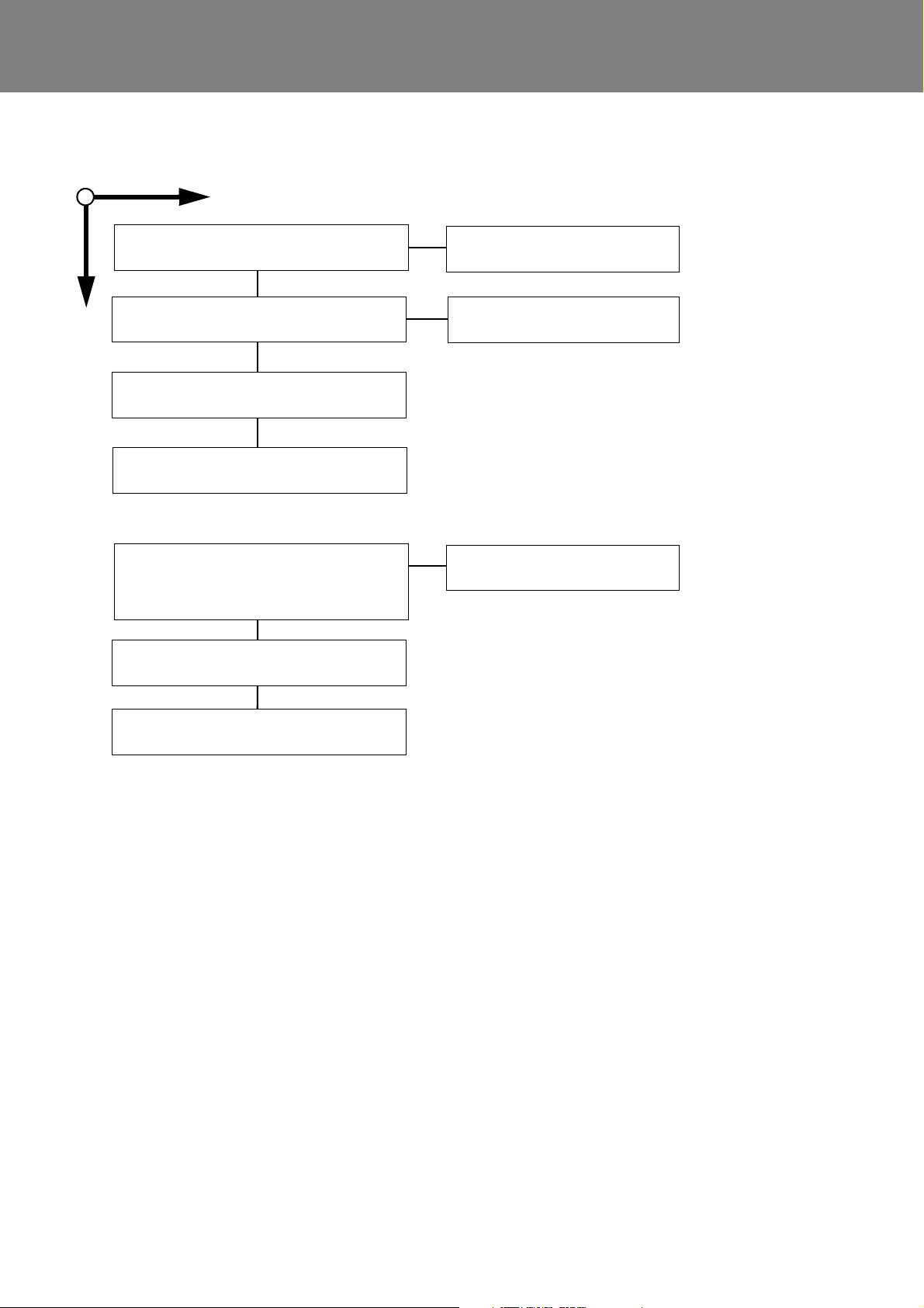
Thermo 230 / 231 / 300 / 301 / 350 5 Troubleshooting
Switch on heater.
Is combustion air fan
operating?
Motor and fan wheel
free to move?
Is fan wheel caught
in cap?
Is voltage present on
plug contact A3?
Check fuses F1/F2/F3
and relais K1, K2 and
replace as required
(control unit 1572
only).
Does trouble persist?
Check motor electrics
and replace as
required.
Replace cap
and fan wheel.
Is voltage too low?
Rated value >20,5 volts
(± 0,5 volts)
Check electrical
wiring and
connections.
Does trouble persist?
Low voltage switch
off during start-up.
Check battery.
Control unit defective,
replace.
Is fuel free of bubbles
in supply and return?
Is fuel filter
contaminated?
Fuel suction line
leak?
Fuel lines empty? Are O-rings in fuel
pump?
Is pump mounted
securely?
Replace fuel filter. Retighten line
connections,
replace lines as
required.
Repeat start (several
times if necessary)
until lines are filled.
Fuel pump defective,
replace.
Is solenoid valve
connected to
electrics?
Connect solenoid
valve.
Is gap between igniter
electrodes ok?
Check gap between
igniter electrodes.
Is nozzle free of foreign
matter and deposits
and properly secured?
Replace nozzle.
YES
NO
Is viewing glass of
flame sensor
contaminated?
Clean window and
viewing glass.
Fuel pump defective,
replace.
Replace O-rings and
screen as needed.
5.3.2 Fault Symptoms
5.3.2.1 Fault Symptom "No Start"
NOTE
Heaters with control unit 1572D:
If the heater performs 8 subsequent attempts to start due
to a malfunction, the heater enters an error lockout and
stops any further attempts to start. This error lockout is
superior to the normal error lockout condition.
The error lockout reset is achieved by switching the
heater on and disconnection of the heater power supply
during run-down.
504

Thermo 230 / 231 / 300 / 301 / 350 5 Troubleshooting
NO
YES
Switch on the heater.
Is the combustion air fan
operating?
Are the power supply,
fuses, plug contacts,
relays o.k.?
(control unit 1572 only)
Replace defective
electrical components.
Is the fuel free of
bubbles in supply and
return?
Is the solenoid valve
o.k.?
(5.3.2.7)
Is the sight glass of the
flame sensor contaminated?
Is the nozzle free of
foreign matter and
deposits?
Is the fuel filter contaminated
or jellied?
Replace solenoid valve
Clean disc and sight
glass.
Replace nozzle.
Replace filter or check the low
temperature rating of the fuel.
Is the fan wheel free to
move?
Control unit defective,
replace.
Is the motor o.k.?
Check the hood, motor
and fan wheel.
Replace the motor.
Is voltage present on plug contact A3? Is electrical wiring
o.k.?
Make electrical
connections.
Replace power supply
line.
YES
NO
Disconnect heater from battery supply.
Is battery properly charged?
Connect heater.
Is voltage between plug contacts A3 and A6
approx. 0.5 volts less than on battery?
Control unit defective, replace.
Is electrical power supply line
to heater o.k.?
Control unit defective,
replace.
5.3.2.2 Fault Symptom "Flame-out"
NOTE:
Heaters with control unit 1572D:
If the heater performs 5 subsequent attempts to start due
to a malfunction, the heater enters an error lockout and
stops any further attempts to start. This error lockout is
superior to the normal error lockout condition.
The error lockout reset is achieved by switching the heater
on and disconnection of the heater power supply during
run-down.
5.3.2.3 Fault Symptom "Low Voltage"
505

Thermo 230 / 231 / 300 / 301 / 350 5 Troubleshooting
NO
YES
Has the heater been in long time operation shortly
before?
Allow heater to cool down and restart (approx.
2min.). Does same symptom show again?
Flame in run-down.
Replace solenoid valve.
Flame sensor defective, replace. Control unit
defective, replace.
Clean combustion tube.
Remove coke deposits.
Control unit defective, replace.
Flame sensor defective, replace.
YES
NO
If replacement of flame sensor does not cure
the problem, replace control unit.
Are electrical lines and contacts to and on
temperature sensor o.k.?
YES
NO
Temperature sensor defective, replace.
WARNING: Water may escape!
If replacement of temperature sensor does not cure
the problem, replace control unit.
Make contacts or replace component.
WARNING: loss of water!
5.3.2.4 Fault Symptom "Foreign Light Detection
during Run-up or Run-down"
5.3.2.5 Fault Symptom "Flame Sensor Defective"
5.3.2.6 Fault Symptom "Temperature Sensor
Defective"
506
Thermo 230 / 231 / 300 / 301 / 350 5 Troubleshooting
NO
YES
Is the solenoid valve supplied
with electrical power?
Has the safety thermostat responded?
(Thermo 231/301 only)
Investigate the reason for the response
(e.g.check the exhaust system)
Replace the solenoid valve.
Make electrical connections.
Safety thermostat in the burner defective, replace.
Is the component test with the diagnostic computer
or the PC heater diagnosis (menu component test)
o.k. (audible click of solenoid valve)?
Does fuel leak from the nozzle in run-down?
Replace the solenoid valve.
Control unit defective, replace.
5.3.2.7 Fault Symptom "Solenoid Valve Defective"
507

Thermo 230 / 231 / 300 / 301 / 350 5 Troubleshooting
Is electrical power supply
to components o.k.?
YES
NO
Has temperature limiter responded
(reset limiter)?
Determine why temperature limiter has responded,
e.g.:
• check shut-off elements,
• check water circulation in system is free from
bubbles,
• check circulation pump sense of rotation,
• check coolant low temperature resistance.
Can no fault be detected?
Make electrical connections.
Control unit defective, replace.
Replace temperature limiter.
If symptom shows again after testing:
control unit defective, replace.
5.3.2.8 Fault Symptom "Temperature Limiter
Defective"
508

Thermo 230 / 231 / 300 / 301 / 350 6 Functional Checkouts
Danger of suffocation!
Warning!
Fastening screw
1 +0.5 Nm
18 20 22 24 26 28 30 32
6
7
8
9
10
11
12
13
14
Voltage
CO
2
- setting at 500 m NN
CO
2
(Vol.-%)
6 Functional Checkouts
6.1 General
This section describes the tests and adjustments on the
heater in installed and removed condition to prove its
serviceability.
The heater must not be operated in closed areas like
garages or workshops with no exhaust ventilation
facilities.
ATTENTION:
To prevent fires do not switch heater on with burner
swung open.
6.2 Adjustments
6.2.1 Adjustment of CO2 Contents
Setting procedure
– measure control unit power supply voltage
– operate heater for approximately 5 min.
–measure CO
contents and soot level and compare
2
with relevant diagram
– soot level target value acc. Bacharach ≤ 4
– loosen fastening screw (refer to Fig.) and reposition
setting ring with fastening screw until rated value is
obtained.
– tighten fastening screw and apply screw seal varnish.
It is allowed to change the manufacturer’s setting for
combustion air quantity by rotation of the setting ring.
NOTE
CO
setting depends on fuel (viscosity) and on geodetic
2
altitude (0.1 % per 100 m).
If proper setting cannot be obtained, proceed as follows:
– check burner head air side for damage and replace if
required
– Check the fuel pump pressure acc. to para. 6.3.5 and
readjust as necessary or replace the fuel pump.
– Inspect fuel filter and fuel pump filter (screen) for
contamination and replace as needed.
– replace fuel nozzle
– measure burner motor speed
Measurement of the CO
value of the exhaust gas
2
must be performed followed by an adjustment of the
combustion air quantity as required in case of:
– repairs on the burner
– irregularities in combustion
– functional checkouts
– nozzle replacement
601

Thermo 230 / 231 / 300 / 301 / 350 6 Functional Checkouts
Water temperature °C
Resistance (Ohm)
1005010
1000
5000
10000
R/y
T/°C
20 °C ≅ 4419 ..... 4892 W
100 °C ≅ 319 ..... 348 W
Viewing glass
Glass bulb
High voltage!
Danger to life!
Warning!
Igniter electrodes 13,000 Volt
10kOhm
6.3 Components Testing
6.3.1 Temperature Sensor Resistance Check
When checking the temperature sensor with a digital
multimeter the values of the following diagram must be
obtained. Resistance checking is preferably performed at
ambient temperatures between 20 °C and approximately
100 °C (immerse sensor in water).
6.3.3 Igniter Electrodes Check
NOTE:
The insulator of the igniter electrodes must show no
damage. Igniter electrodes with a gap out of tolerance or
not working properly must be replaced.
Check
– inspect insulators of igniter electrodes for damage
6.3.4 Igniter Box Check
NOTE:
The igniter box may also be tested using the PC heater
diagnosis (component test).
High voltage; 13,000 volts arcing across the igniter
electrodes.
ATTENTION:
Do not apply voltage to igniter box without electrodes.
6.3.2 Flame Sensor Resistance Check
NOTE:
The glass bulb of the flame sensor and the viewing glass
of the window (refer to Fig.) are to be cleaned if
contaminated. In case of damage or not obtaining the
rated values replace flame sensor.
Check
– cover flame sensor glass bulb
– check resistance (rated value: < 20 kOhm)
– uncover flame sensor glass bulb and expose to light
of strong lamp.
– check resistance (rated value: < 400 Ohm)
Check
– apply 24V as shown on figure
– normal condition: spark between electrodes.
602

Thermo 230 / 231 / 300 / 301 / 350 6 Functional Checkouts
Pump pressure test gauge
with bleeding feature
2500 3000
8
8,5
9
9,5
10
10,5
11
4000 5000 6000 7000 8000 8500
Thermo 350
Thermo 300
Thermo 230
Speed (min-1)
Pump pressure in relation to speed
Pump pressure (bar)
Adjustment screw
pump pressure
Note: Pump displayed when removed.
6.3.5 Fuel Pump Check
6.3.5.1 Fuel Pump Check on Heaters with Control Unit
1572
A pressure test gauge with a display range from 0 to 15
bar as well as a bleeding feature is required (see Fig.
below). The pressure test gauge can be obtained from a
Spheros Service Center or a distribution partner.
pressure despite readjustment not be achieved or
occur leaks, the fuel pump must be replaced.
– switch off heater.
– unscrew test gauge.
As prescribed, the fuel pump and the fuel hoses must be
replaced every 5 years.
The igniter box must be removed for safety reasons.
Check
– remove igniter box (refer to 9.2.8.1).
– remove nozzle.
– screw on test gauge.
– cover flame sensor.
– switch on heater.
– Open the bleed port at the pressure test gauge until
some fuel escapes, collect it e.g. with a cloth. Close
the bleed port and read the present pressure at the
gauge.
– after approximately 13 sec. pump pressure is
indicated (refer to diagram).
– If the specified pressure cannot be reached, it can be
readjusted. For that rotate the adjusting screw (see
Fig. below) max. one revolution. If the prescribed
ATTENTION:
ATTENTION:
Do not tuch or damage nozzle bore.
– Screw in nozzle and tighten (see 9.2.7.2).
– Install igniter box (refer to 9.2.8.2).
6.3.5.2 Fuel Pump Check on Heaters with
Control Unit 1572D
NOTE:
The fuel pump check of heaters with control unit 1572D
can also be done using the PC heater diagnosis in the
menu component test.
As prescribed, the fuel pump and the fuel hoses must be
replaced every 5 years.
Check
– remove nozzle.
603

Thermo 230 / 231 / 300 / 301 / 350 6 Functional Checkouts
20 22 24 26
28
30 32
2500
18
3000
3500
4000
4500
5000
5500
6000
6500
7000
7500
8000
Thermo 350
Thermo 300
Thermo 230
Voltage
Speed (1/min.)
– screw on the test gauge with bleeding feature.
– Follow the instructions in the menu component test of
the PC heater diagnosis.
– Open the bleed port at the pressure test gauge until
some fuel escapes, collect it e.g. with a cloth. Close
the bleed port and read the present pressure at the
gauge.
– after approximately 13 sec. pump pressure is
indicated (refer to the diagram above).
– If the specified pressure cannot be reached, it can be
readjusted. For that rotate the adjusting screw max.
one revolution. If the prescribed pressure despite
readjustment not be achieved or occur leaks, the fuel
pump must be replaced.
– screw in nozzle and torque with 20 Nm.
ATTENTION:
Do not tuch or damage nozzle bore.
6.3.6 Fan Motor Check
NOTE:
The fan motor check is performed with the burner
installed. If normal conditions are not obtained the fan
motor must be replaced.
6.3.7 Solenoid Valve Check
NOTE:
A solenoid valve leaking valve seat shows by rather long
smoke emissions during run-down. In this case fuel keeps
dripping through the fuel nozzle.
Short smoke emissions are normal caused by clearing the
area between solenoid valve and nozzle bore.
Check
ATTENTION:
Disconnect solenoid valve connector from control
unit to avoid damage to the control unit.
– Check electrics for the following values:
• break voltage 17.0 Volts
• operating voltage 19.2 ... 28.8 Volts
• power consumption at
nominal voltage and 20 °C 10 Watts
• nominal current 0.42 Amps
NOTE:
On heaters with control unit 1572 the solenoid valve may
also be checked by means of the PC heater diagnosis
(component test).
Check
– check fan motor bearing condition(binding)
– measure heater power supply voltage
– switch on heater
– measure speed and compare with the diagram below
Thermo 230/231 4400 ±350 24 Volt
Thermo 300/301 5200 ±420 24 Volt
Thermo 230 6200 ±500 24 Volt
6.3.8 Nozzle Block Preheater Check
NOTE:
At a temperature of < 0 °C the heater cartridge in the
nozzle block is activated. The heating period depends on
the heat reflected within the combustion chamber.
Preheating is deactivated when the thermostat ambient
temperature is +8 °C.
Power consumption is 130 ±13 Watts at 24 Volt.
Check
– swing burner head open or remove
– disconnect electrical connector from nozzle
– connect ohmmeter to connector
– using cooling spray cool down thermostat or bridge
– resistance (max. 4.5 Ω).
604

Thermo 230 / 231 / 300 / 301 / 350 7 Circuit Diagrams
7 Circuit Diagrams
7.1 General
The circuit diagrams (Fig. 701 and 702) show possible
heater circuits for Thermo 230, 300 and 350 with control
unit 1572 and with
–switch
– timer 1529 (triple timer)
The circuit diagrams (Fig. 703 and 704) show possible
heater circuits for Thermo 230, 231, 300, 301 and 350
with control unit 1572D and with
–switch
– standard timer 1531
The circuit diagrams (Fig. 705 thru 710) show possible
heater circuits for Thermo 230, 231, 300, 301 and 350
with control unit 1572D
701

Thermo 230 / 231 / 300 / 301 / 350 7 Circuit Diagrams
Item Nomenclature Remark
A1 Heater not grounded
A2 Control unit SG 1572
B1 Flame sensor
B2 Temperature sensor
B3 Temperature limiter
B4 Thermostat open at T > 8 °C
E1 Heating cartridge for nozzle preheating
F2 Fuse 25A flat fuse SAE J 1284
F3 Fuse 25A flat fuse SAE J 1284
H1 Light operation indicator light
K1 Relay (in item A2) for circulation pump
K2 Relay (in item A2) for combustion air fan /
heating cartridge
M1 Motor combustion air fan
M2 Motor circulation pump
S1 Switch on / off
S2 Continuity switch on water cock
Item Nomenclature Remark
S3 Switch,
Ext. pump trigger
S4 Switch power save operation
U1 Igniter box
U2 Igniter electrodes
A Plug connections, 6-pole
C Plug connections, 1-pole
D Plug connections, 4-pole
X1 Plug connections, 6-pole
X2 Plug connections, 2-pole
X3 Plug connections, 8-pole
Y1 Solenoid valve
1 Diagnostic connector
33
51
15
62
2
6
1
2
44
4
3
3
2
2
1
1
4
F1
B2
Y1
br
gr
or
gn
ϑ
ϑ
rt/ws
bl
or
br
br
sw
rt
sw
A2
X1
A
X3
D
X2
C
K2
K1
M1
M2
H2H1
B3
B4
S2
S3
S4
S1
A1
B1
E1
U2
U1
SE
-
+
M
M
M1
A2
U1
A1
B1
Y1
F1/B3E1B2
br
F3 F2
30
30
31
31
X3
8765432
1
2
1
X2
X1
1
3
5
2
4
6
D
C
A
6
5
4
3
2
1
bl
br
ge
gn
gr
or
rt
sw
vi
ws
Wire colors
blue
brown
yellow
green
gray
orange
red
black
violet
white
Wire gauges
< 7,5 m 7,5 - 15 m
0,75 mm
2
1,0 mm
2
1,5 mm
2
2,5 mm
2
4,0 mm
2
1,5 mm
2
1,5 mm
2
2,5 mm
2
4,0 mm
2
6,0 mm
2
1
Fig. 701: Automatic Control Circuit with Control Unit 1572 and Switch
702

Thermo 230 / 231 / 300 / 301 / 350 7 Circuit Diagrams
Item Nomenclature Remark
A1 Heater not grounded
A2 Control unit SG 1572
B1 Flame sensor
B2 Temperature sensor
B3 Temperature limiter
B4 Thermostat open at T > 8 °C
E1 Heating cartridge for nozzle preheating
F2 Fuse 25A flat fuse SAE J 1284
F3 Fuse 25A flat fuse SAE J 1284
F6 Fuse 5A flat fuse SAE J 1284
H3 Light in pos. P symbol lighting
H4 Symb. “Heating“ on display operation indicator light
K1 Relay (in item A2) for circulation pump
K2 Relay (in item A2) for combustion air fan /
heating cartridge
M1 Motor combustion air fan
M2 Motor circulation pump
P Pre-selection timer (1529) for pre-selection operation
Item Nomenclature Remark
S2 Continuity switch on water cock
S3 Switch,
Ext. pump trigger
S4 Switch power save operation
U1 Igniter box
U2 Igniter electrodes
A Plug connections, 6-pole
C Plug connections, 1-pole
D Plug connections, 4-pole
X1 Plug connections, 6-pole
X2 Plug connections, 2-pole
X3 Plug connections, 8-pole
X4 Plug connections, 8-pole
Y1 Solenoid valve
bl
br
ge
gn
gr
or
rt
sw
vi
ws
Wire colors
blue
brown
yellow
green
gray
orange
red
black
violet
white
Wire gauges
< 7,5 m 7,5 - 15 m
0,75 mm
2
1,0 mm
2
1,5 mm
2
2,5 mm
2
4,0 mm
2
1,5 mm
2
1,5 mm
2
2,5 mm
2
4,0 mm
2
6,0 mm
2
X4
7
33
51
15
62
2
6
1
2
44
3
4
3
3
2
2
1
1
4
2648
5
H3
P
H4
F1
B2
Y1
br
gr
or
gn
ϑ
ϑ
rt/ws
bl
or
br
br
sw
rt
sw
A2
X1
A
X3
D
X2
C
K2
K1
M1
M2
H2
B3
B4
S2
S3
S4
A1
B1
E1
U2
U1
SE
-
+
M
M
X4
12345678
X3
8765432
1
2
1
X2
X1
1
3
5
2
4
6
M1
A2
U1
A1
B1
Y1
F1/B3E1B2
br
br
58
75(15)
58
75(15)
F3 F6 F2
30
30
31
31
D
C
A
6
5
4
3
2
1
1
2
34
1 Diagnostic connector
2 to vehicle terminal +75 if available, otherwise terminal 15
3 Timer P:
with plus to connection 4 = continuous operation during immediate heating
without plus to connection 4 = heating period 1 hour
4 vehicle lighting terminal 58
Fig. 702: Automatic Control Circuit with Control Unit 1572 and Timer (Triple Timer)
703

Thermo 230 / 231 / 300 / 301 / 350 7 Circuit Diagrams
Item Nomenclature Remark
A1 Heater not grounded
A2 Control unit SG 1572
B1 Flame sensor observe polarity
B2 Temperature sensor polarity optional
B3 Temperature limiter
B4 Thermostat for nozzle preheating
B5 Thermostat alternative to B3
B6 Thermostat for vertical installation (MV Y1)
E1 Heating cartridge for nozzle preheating
F1 Fuse 5A flat fuse acc. DIN 72581 part 3
F2 Fuse 25A flat fuse acc. DIN 72581 part 3
F3 Fuse 25A flat fuse acc. DIN 72581 part 3
H1 Light operation indicator light
H2 Light flame indication light
M1 Motor combustion air fan
M2 Motor circulation pump
S1 Switch on / off
Item Nomenclature Remark
S3 Switch ext. pump trigger
S4 Switch power save operation
U1 Igniter box
U2 Igniter electrodes
W1 wire harness (1)
W2 wire harness (2)
A Plug connections, 6-pole
C Plug connections, 1-pole
D Plug connections, 4-pole
F Plug connections, 2-pole
X1 Plug connections, 6-pole
X2 Plug connections, 2-pole
X3 Plug connections, 8-pole
Y1 Solenoid valve
bl
br
ge
gn
gr
or
rt
sw
vi
ws
Wire colors
blue
brown
yellow
green
gray
orange
red
black
violet
white
Wire gauges
< 7,5 m 7,5 - 15 m
0,75 mm
2
1,0 mm
2
1,5 mm
2
2,5 mm
2
4,0 mm
2
1,5 mm
2
1,5 mm
2
2,5 mm
2
4,0 mm
2
6,0 mm
2
1 Diagnostic connector
3 Pin assignment: Pin assignment 4wire lead 7wire lead
D1 0,75 gr 0,75 rt
D2 0,75 or 0,75 or
D3 0,75 gn 0,75 bl
D4 0,75 br 2,0 br
F1 nicht belegt 2,0 sw
F2 nicht belegt 2,0 rt/ws
4 with connection to terminal 61 auxiliary
3
3
3
3
3
3
4
1
Fig. 703: Automatic Control Circuit with Control Unit 1572D and Switch
704

Thermo 230 / 231 / 300 / 301 / 350 7 Circuit Diagrams
bl
br
ge
gn
gr
or
rt
sw
vi
ws
Wire colors
blue
brown
yellow
green
gray
orange
red
black
violet
white
Wire gauges
< 7,5 m 7,5 - 15 m
0,75 mm
2
1,0 mm
2
1,5 mm
2
2,5 mm
2
4,0 mm
2
1,5 mm
2
1,5 mm
2
2,5 mm
2
4,0 mm
2
6,0 mm
2
1 Diagnostic connector
2 Timer P:
with plus to connection 10 = continuous operating during immediate heating
terminal 10 not connected = duration of heating programmable (10 min to 120 min);
3 Pin assignment: Pin assignment 4wire lead 7wire lead
D1 0,75 gr 0,75 rt
D2 0,75 or 0,75 or
D3 0,75 gn 0,75 bl
D4 0,75 br 2,0 br
F1 not used 2,0 sw
F2 not used 2,0 rt/ws
4 with connection to terminal 61 auxiliary
Item Nomenclature Remark
A1 Heater
A2 Control unit SG 1572D
B1 Flame sensor observe polarity
B2 Temperature sensor polarity optional
B3 Temperature limiter
B4 Thermostat for nozzle preheating
B5 Thermostat alternative to B3
B6 Thermostat for vertical installation (MV Y1)
E1 Heating cartridge for nozzle preheating
F1 Fuse 5A flat fuse acc. DIN 72581 part 3
F2 Fuse 25A flat fuse acc. DIN 72581 part 3
F3 Fuse 25A flat fuse acc. DIN 72581 part 3
H1 Light operation indicator light
H2 Light flame indication light
H4 Symb. “Heating“ on display operation indicator light (in pos. P)
M1 Motor combustion air fan
M2 Motor circulation pump
P Pre-selection timer for pre-selection operation
Item Nomenclature Remark
S3 Switch ext. pump trigger
S4 Switch power save operation
U1 Igniter box
U2 Igniter electrodes
W1 wire harness (1)
W2 wire harness (2)
A Plug connections, 6-pole
C Plug connections, 1-pole
D Plug connections, 4-pole
F Plug connections, 2-pole
X1 Plug connections, 6-pole
X2 Plug connections, 2-pole
X3 Plug connections, 8-pole
X4 Plug connections, 12-pole
Y1 Solenoid valve
1
4
3
3
3
3
3
3
2
Fig. 704: Automatic Control Circuit with Control Unit 1572D and Standard Timer
705

Thermo 230 / 231 / 300 / 301 / 350 7 Circuit Diagrams
3
5
2
6
4
rt/ws
br
rt
M1
B4
A1
E1
U2
U1
SE
-
+
M
3
1
1
5
4
3
3
2
2
1
1
4
B2
Y1
ϑ
sw
A2
X1
A
D
H2
S3
S4
S1
B1
F1
F2
30
30
C
W1
31
31
D
4
3
2
1
A
6
5
4
3
2
1
DEUTSCH
2
4
ϑ
B3
2
1
1
32
7
61
61
rt/sw
sw
bl
or
rt
br
X3
D+
FA K
BA
SP
F3
br
sw
X2
1
2
M2
M
6
7
6
5
Signal UP
UPFA
C
sw
sw
H1
F
X1
X3
X2
2
1
F
M1
A2
U1
A1
B1
Y1 E1
B2
B3/B5
bl
br
ge
gn
gr
or
rt
sw
vi
ws
Wire colors
blue
brown
yellow
green
gray
orange
red
black
violet
white
Wire gauges
< 7,5 m 7,5 - 15 m
0,75 mm
2
1,0 mm
2
1,5 mm
2
2,5 mm
2
4,0 mm
2
1,5 mm
2
1,5 mm
2
2,5 mm
2
4,0 mm
2
6,0 mm
2
Item Nomenclature Remark
A1 Heater
A2 Control unit SG 1572D
B1 Flame sensor observe polarity
B2 Temperature sensor polarity optional
B3 Temperature limiter
B4 Thermostat for nozzle preheating
E1 Heating cartridge for nozzle preheating
F1 Fuse 25A flat fuse acc. DIN 72581 part 3
F2 Fuse 25A flat fuse acc. DIN 72581 part 3
F3 Fuse 5A flat fuse acc. DIN 72581 part 3
H1 Light operation indicator light
H2 Light flame indication light
M1 Motor combustion air fan
M2 Motor circulation pump
S1 Switch on / off
Item Nomenclature Remark
S3 Switch ext. pump trigger
S4 Switch power save operation
U1 Igniter box
U2 Igniter electrodes
W1 wire harness (1+2)
A Plug connections, 6-pole
C Plug connections, 1-pole
D Plug connections, 4-pole
F Plug connections, 2-pole
X1 Plug connections, 7-pole
X2 Plug connections, 2-pole
X3 Plug connections, 7-pole
Y1 Solenoid valve
1
1
1 Diagnostic connector
Fig. 705: System wiring diagram Daimler Chrysler Citaro, Ident no. 67131
706

Thermo 230 / 231 / 300 / 301 / 350 7 Circuit Diagrams
3
3
1
1
5
2
2
6
4
4
3
8
2
6
1
5
4
B2
Y1
br
gr
or
gn
ϑ
rt/ws
bl
or
br
br
sw
rt
sw
A2
A
D
X2
C
K2
K1
M1
H2
B4
S2
S3
S4
S1
A1
B1
E1
U2
U1
SE
-
+
M
F3
F2
30
30
W1
H1
1
3
M2
M
7
10
16
15
-31
-31
9
rt
rt
sw
ϑ
B3
C
D
4
3
2
1
X2
1
2
3
4
X1
A
M1
A2
U1
A1
B1
Y1
F1/B3E1B2
X1
A
6
5
4
3
2
1
DEUTSCH
1
2
3
6
7
5
8
9
10
11
12
13
14
4
15
16
A
bl
br
ge
gn
gr
or
rt
sw
vi
ws
Wire colors
blue
brown
yellow
green
gray
orange
red
black
violet
white
Wire gauges
< 7,5 m 7,5 - 15 m
0,75 mm
2
1,0 mm
2
1,5 mm
2
2,5 mm
2
4,0 mm
2
1,5 mm
2
1,5 mm
2
2,5 mm
2
4,0 mm
2
6,0 mm
2
1
Item Nomenclature Remark
A1 Heater not grounded
A2 Control unit SG 1572
B1 Flame sensor observe polarity
B2 Temperature sensor polarity optional
B3 Temperature limiter alternative to F1
B4 Thermostat for nozzle preheating
B5 Fire guard Van Hool
E1 Heating cartridge
F2 Fuse see table
F3 Fuse see table
H1 Light operation indicator
H2 Light flame indicator
K1 Relay for circulation pump
K2 Relay for combustion air fan
M1 Motor combustion air fan
M2 Motor circulation pump
S1 Switch on / off
Item Nomenclature Remark
S2 Continuity switch on water cock
S3 Switch,
Ext. pump trigger
required, if S2 does not exist
S4 Switch power save operation
U1 Igniter box
U2 Igniter electrodes
W1 Wiring harness Van Hool
A Plug connections, 6-pole
C Plug connections, 1-pole
D Plug connections, 4-pole
X1 Plug connections, 16-pole
X2 Plug connections, 4-pole
Y1 Solenoid valve
1 Diagnostic connector
Fuses acc. to SAE J 1284
DW230 DW300 DW350
F2 25A / 16A 25A / 16A 25A / 16A
F3 25A / 16A 25A / 16A 25A / 16A
Fig. 706: System wiring diagram Van Hool, Ident no. 89401
707

Thermo 230 / 231 / 300 / 301 / 350 7 Circuit Diagrams
33
51
15
6
2
2
6
1
2
44
4
3
3
2
2
1
1
4
F1
B2
Y1
br
gr
or
gn
ϑ
ϑ
rt/ws
bl
or
br
br
sw
rt
sw
A2
X1
A
X3
D
X2
C
K2
K1
M1
M2
H2H1
B3
B4
S2
S3
S4
S1
A1
B1
E1
U2
U1
SE
-
+
M
M
M1
A2
U1
A1
B1
Y1
F1/B3E1B2
F3 F2
30
30
C
W1
W2
-31
-31
D
4
3
2
1
X3
8
7
654
3
2
1
2
1
X2
X1
1
3
5
2
4
6
A
6
5
4
3
2
1
DEUTSCH
bl
br
ge
gn
gr
or
rt
sw
vi
ws
Wire colors
blue
brown
yellow
green
gray
orange
red
black
violet
white
Wire gauges
< 7,5 m 7,5 - 15 m
0,75 mm
2
1,0 mm
2
1,5 mm
2
2,5 mm
2
4,0 mm
2
1,5 mm
2
1,5 mm
2
2,5 mm
2
4,0 mm
2
6,0 mm
2
1
Item Nomenclature Remark
A1 Heater not grounded
A2 Control unit SG 1572
B1 Flame sensor observe polarity
B2 Temperature sensor polarity optional
B3 Temperature limiter alternative to F1
B4 Thermostat for nozzle preheating
E1 Heating cartridge
F2 Fuse see table
F3 Fuse see table
H1 Light operation indicator
H2 Light flame indicator
K1 Relay for circulation pump
K2 Relay for combustion air fan
M1 Motor combustion air fan
M2 Motor circulation pump
S1 Switch on / off
Item Nomenclature Remark
S2 Continuity switch on water cock
S3 Switch,
Ext. pump trigger
required, if S2 does not exist
S4 Switch power save operation
U1 Igniter box
U2 Igniter electrodes
W1 Wiring harness (1)
W2 Wiring harness (2)
A Plug connections, 6-pole
C Plug connections, 1-pole
D Plug connections, 4-pole
X1 Plug connections, 6-pole
X2 Plug connections, 2-pole
X3 Plug connections, 8-pole
Y1 Solenoid valve
1 Diagnostic connector
Fuses acc. to SAE J 1284
DW230 DW300 DW350
F2 25A / 16A 25A / 16A 25A / 16A
F3 25A / 16A 25A / 16A 25A / 16A
Fig. 707: System wiring diagram O405 / O407 / O408, Ident no. 91292
708

Thermo 230 / 231 / 300 / 301 / 350 7 Circuit Diagrams
3
6
2
6
1
2
4
rt/ws
bl
br
sw
rt
C
M1
M2
H1
B4
A1
E1
U2
U1
SE
-
+
M
M
3
5
1
15
4
3
3
2
2
1
1
4
B2
Y1
ϑ
or
sw
A2
X1
A
X2
D
H2
S2
S3
S4
S1
B1
F1
F2
30
30
C
W1
W2
31
31
2
7
4
ϑ
B3
2
1
1
32
1
5
61
61
rt/sw
sw
bl
or
rt
br
X3
D+
LFAK
M
SP
2
1
F
D
4
3
2
1
F
M1
A2
U1
A1
B1
Y1 E1
B2
B3/B5
X1
1
2
3
4
5
8
7
7
X2
X3
A
1
2
3
4
5
A
A
6
5
4
3
2
1
DEUTSCH
bl
br
ge
gn
gr
or
rt
sw
vi
ws
Wire colors
blue
brown
yellow
green
gray
orange
red
black
violet
white
Wire gauges
< 7,5 m 7,5 - 15 m
0,75 mm
2
1,0 mm
2
1,5 mm
2
2,5 mm
2
4,0 mm
2
1,5 mm
2
1,5 mm
2
2,5 mm
2
4,0 mm
2
6,0 mm
2
1
Item Nomenclature Remark
A1 Heater not grounded
A2 Control unit SG 1572D
B1 Flame sensor observe polarity
B2 Temperature sensor polarity optional
B3 Temperature limiter
B4 Thermostat for nozzle preheating
E1 Heating cartridge for nozzle preheating
F2 Fuse 25A flat fuse acc. DIN 72581 part 3
F3 Fuse 25A flat fuse acc. DIN 72581 part 3
H1 Light operation indicator
H2 Light flame indicator
M1 Motor combustion air fan
M2 Motor circulation pump
S1 Switch on / off
S2 Continuity switch on water cock
S3 Switch,
Ext. pump trigger
required, if S2 does not exist
S4 Switch power save operation
Item Nomenclature Remark
U1 Igniter box
U2 Igniter electrodes
W1 Wiring harness (1)
W2 Wiring harness (2)
A Plug connections, 6-pole
C Plug connections, 1-pole
D Plug connections, 4-pole
F Plug connections, 2-pole
X1 Plug connections, 6-pole
X2 Plug connections, 2-pole
X3 Plug connections, 8-pole
Y1 Solenoid valve
1 Diagnostic connector
1
Fig. 708: System wiring diagram MAN, Ident no. 89404
709

Thermo 230 / 231 / 300 / 301 / 350 7 Circuit Diagrams
3
5
2
6
4
rt/ws
br
rt
M1
B4
A1
E1
U2
U1
SE
-
+
M
3
1
1
5
3
3
2
2
1
1
4
B2
Y1
ϑ
sw
A2
X1
A
H2
S4
B1
F1
F2
30
30
C
W1
-31
-31
D
4
3
2
1
A
6
5
4
3
2
1
DEUTSCH
2
4
2
1
1
3
2
4
61
61
X3
D+
FA K
SP
F3
sw
X2
1
2
M2
C
F
W2
5
6
M
H1
or
bl
6
B6
ϑ
B3
ϑ
D
L
S2
S3
S1
M
Y2
3
2
1
X5
br
sw
rt/ws
br
rt
or
bl
sw
B5
ϑ
2
1
br
bl
X1
8
7
654
3
2
1
9
10
7
X4
F
2
1
X3
2
1
X3
8
7
654
3
2
1
X4/X5
4
3
2
1
M1
A2
U1
A1
B1
Y1 E1
B2
B3/B6
bl
br
ge
gn
gr
or
rt
sw
vi
ws
Wire colors
blue
brown
yellow
green
gray
orange
red
black
violet
white
Wire gauges
< 7,5 m 7,5 - 15 m
0,75 mm
2
1,0 mm
2
1,5 mm
2
2,5 mm
2
4,0 mm
2
1,5 mm
2
1,5 mm
2
2,5 mm
2
4,0 mm
2
6,0 mm
2
1
Item Nomenclature Remark
A1 Heater not grounded
A2 Control unit SG 1572
B1 Flame sensor observe polarity
B2 Temperature sensor polarity optional
B3 Temperature limiter
B4 Thermostat for nozzle preheating
B5 Temperature sensor, external observe polarity
B6 Thermostat alternative to B3
E1 Heating cartridge for nozzle preheating
F1 Fuse 25A flat fuse acc. DIN 72581 part 3
F2 Fuse 25A flat fuse acc. DIN 72581 part 3
F3 Fuse 5A flat fuse acc. DIN 72581 part 3
H1 Light operation indicator
H2 Light flame indicator
M1 Motor combustion air fan
M2 Motor circulation pump
S1 Switch on / off
S2 Continuity switch on water cock
Item Nomenclature Remark
S3 Switch, Ext. pump trigger required, if S2 does not exist
S4 Switch power save operation
U1 Igniter box
U2 Igniter electrodes
W1 Wiring harness (1)
W2 Wiring harness (2)
A Plug connections, 6-pole
C Plug connections, 1-pole
D Plug connections, 4-pole
F Plug connections, 2-pole
X1 Plug connections, 10-pole
X2 Plug connections, 2-pole
X3 Plug connections, 8-pole
X4 Plug connections, 4-pole
X5 Plug connections, 4-pole
Y1 Solenoid valve
Y2 Shut-off valve with filter
1 Diagnostic connector
1
Fig. 709: System wiring diagram SETRA, Ident no. 90972
710

Thermo 230 / 231 / 300 / 301 / 350 7 Circuit Diagrams
1 Diagnostic connector
2 Timer P:
with plus to connection 10 = continuous operating during immediate heating
terminal 10 not connected = duration of heating programmable (10 min to 120 min);
3 Pin assignment: Pin assignment 4wire lead 7wire lead
D1 0,75 gr 0,75 rt
D2 0,75 or 0,75 or
D3 0,75 gn 0,75 bl
D4 0,75 br 2,0 br
F1 not used 2,0 sw
F2 not used 2,0 rt/ws
5 Option
bl
br
ge
gn
gr
or
rt
sw
vi
ws
Wire colors
blue
brown
yellow
green
gray
orange
red
black
violet
white
Wire gauges
< 7,5 m 7,5 - 15 m
0,75 mm
2
1,0 mm
2
1,5 mm
2
2,5 mm
2
4,0 mm
2
1,5 mm
2
1,5 mm
2
2,5 mm
2
4,0 mm
2
6,0 mm
2
Item Nomenclature Remark
A1 Heater not grounded
A2 Control unit SG 1572
B1 Flame sensor observe polarity
B2 Temperature sensor polarity optional
B3 Temperature limiter
B4 Thermostat for nozzle preheating
B5 Thermostat alternative to B3
B6 Thermostat for vertical installation (MV Y1)
E Filter heating
E1 Heating cartridge for nozzle preheating
F1 Fuse 5A flat fuse acc. DIN 72581 part 3
F2 Fuse 25A flat fuse acc. DIN 72581 part 3
F3 Fuse 25A flat fuse acc. DIN 72581 part 3
F4 Fuse 25A flat fuse acc. DIN 72581 part 3
F5 Fuse 5A flat fuse acc. DIN 72581 part 3
F6 Fuse 5A flat fuse acc. DIN 72581 part 3
F7 Fuse 5A flat fuse acc. DIN 72581 part 3
H1 Light operation indicator
H2 Light flame indicator
H4 Symb. “Heating“ on display operation indicator light (in pos. P)
K4 Relay
M1 Motor combustion air fan
M2 Motor circulation pump
P Pre-selection timer for pre-selection operation
Item Nomenclature Remark
S1 Switch on / off
S3 Switch ext. pump trigger
S4 Switch power save operation
S5 Switch aux. heating
S6 Switch filter heating on
T Temperature switch filter heating
U1 Igniter box
U2 Igniter electrodes
W1 Wiring harness (1)
W2 Wiring harness (2)
W3 Wiring harness (3)
A Plug connections, 6-pole
C Plug connections, 1-pole
D Plug connections, 4-pole
F Plug connections, 2-pole
O Plug connections, 2-pole
Q Plug connections, 2-pole
X1 Plug connections, 4-pole
X2 Plug connections, 2-pole
X3 Plug connections,7-pole
X4 Plug connections, 12-pole
X5 Plug connections, 4-pole
Y1 Solenoid valve
Fig. 710: Automatic Control Circuit Rail with Control Unit 1572D, standard timer and filter heating
711

Thermo 230 / 231 / 300 / 301 / 350 8 Servicing
Heaters manufactured
from beginning of 1996
up to 1998, calendar
week 36; 3G......)
Identification
label
Exhaust muffler
8 Servicing
8.1 General
This section describes the servicing procedures allowed
on the heater when installed.
8.2 Heater Servicing
As long as the heater is in operation or in run-down the
battery main power supply must not be disconnected to
prevent the heater from overheating by response of the
overheat protection.
When performing long time repairs on the heater its
removal is appropriate.
After working on the heating circuit replenish with a
coolant mix prepared with water and anti-freeze and
bleed circuit afterwards according to manufacturer’s
instructions.
8.3 Vehicle Servicing
8.5.1 Inspection and Attachment of the Exhaust
Muffler (only heaters from year of
production 1996 and up to production
date 1996, calendar week 36; 3G......)
NOTE:
If the exhaust muffler is already secured with a sheet
metal screw, the following procedure need not be
performed.
General
The exhaust muffler of heaters manufactured from the
beginning of 1996 up to a manufacturing date of 1998
(calendar week 36; 3G.......) (for year or date of production
refer to identification label) the exhaust muffler may get
loose or lost under certain circumstances. Therefore an
inspection for proper attachment of the muffler should be
performed.
In the vicinity of the heater a temperature of 110 °C
must under no circumstances be exceeded (e.g.
during paint work on the vehicle).
8.4 Heater Test Run
The heater must not be operated, not even with the timer,
in enclosed areas like garages or workshops not equipped
with exhaust ventilation facilities.
8.5 Maintenance
The heater should be inspected in periodic time intervals,
latest at the beginning of the heating period (time of increased heater usage due to present weather conditions),
refer to Maintenance plan in Appendix A-1.
ATTENTION:
801

Thermo 230 / 231 / 300 / 301 / 350 8 Servicing
Sheet metal
screw
B 3.9 x 25
Sheet metal screw
B 3.9 x 25
Hole
2.5 mm Ø
Hole
2.5 mm Ø
Exhaust muffler
(ident. no. 206 91D)
Exhaust muffler
(ident. no. 206 91D)
Exhaust end pipe
Exhaust
end pipe
Exhaust deflector
(ident. no. 849 70A)
Exhaust pipe
Slot exhaust
pipe
Heater without exhaust pipe
Heater with exhaust pipe
Inspection and Attachment
NOTE:
The exhaust muffler must always be secured with a sheet
metal screw. Drill a hole with a diameter of 2.5 mm into
the exhaust end pipe and muffler and arrest muffler with a
sheet metal screw B 3.9 x 25 (see figure).
1. Check exhaust end pipe for presence of muffler.
For checking remove exhaust end pipe as required.
2. If muffler is found in exhaust end pipe fasten as
described in NOTE. Slot or drill exhaust end pipe and
refit.
3. If no muffler is found in exhaust end pipe check if
muffler is upstream in exhaust pipe. If muffler is
dislocated in the exhaust pipe, arrest muffler as
described in NOTE. Slot or drill exhaust pipe and refit.
4. If the exhaust muffler has been lost it may be ordered
from Spheros (ident. no. 206 91D). Fasten muffler
according to NOTE. Slot or drill exhaust pipe and refit.
5. If heater is operated without exhaust pipe, fasten
muffler according to NOTE. An exhaust deflector must
be additionally fitted.
802

Thermo 230 / 231 / 300 / 301 / 350 8 Servicing
High voltage!
Danger to life!
Warning!
1
2
3
4
NOTE
Depending on the burner head direction of swing the
cotter pin may be located on the opposite side.
7.5 +1 Nm
8.5.2 Burner Head Opening and Closing
The igniter box operates with high voltage. Prior to
opening the burner head the connectors of the cable
harness in the vehicle have to be disconnected to
prevent lethal injuries.
After closing burner head, reconnect connectors in the
vehicle.
NOTE:
Maintenance on the heater is easy. By swinging the
burner head open the following components become
accessible:
– fuel pump and fuel nozzle
– solenoid valve
– igniter box
– igniter electrodes
–flame sensor
– combustion chamber
– nozzle block preheater (if installed)
In order to obtain a convenient burner head opening angle
it is required to disconnect the electrical connection(s) to
the temperature limiter and temperature sensor.
Opening
1. Disconnect electrical connections to temperature
limiter and temperature sensor.
2. Loosen nuts (3, Fig. 801) enough to release hinge
bolts (2).
3. Swing hinge bolts (2) outwards.
4. Swing burner head (4) away.
Closing
1. If required engage burner head (4, Fig. 801) into the
hinge and secure it using the cotter pin (1).
2. Swing burner head (4) into closed position.
3. Swing hinge bolts (2) into lock position and secure
with nuts (3).
4. Tighten nuts (3).
5. Reconnect electrical connections to the temperature
limiter and temperature sensor.
NOTE
When making electrical connections observe wiring color
codes.
Fig. 801 Swinging Burner Head open
803

Thermo 230 / 231 / 300 / 301 / 350 8 Servicing
8.6 Visual Inspections and Regulations
for Installation
8.6.1 Connection to Vehicle Cooling System
The installation of the heater should be in a location as low
as possible to ensure self-venting of the heater and circulation pump. This applies in particular for the circulation
pump because it is not self-sucking.
The heater is to be connected to the vehicle cooling
system according to Fig. 802. The cooling system coolant
capacity must be at least 10 liters.
The vehicle cooling system or the separate heating circuit
must use only pressure relief valves with an opening
pressure of at least 0.4 bar and of max. 2.0 bar.
It is a basic requirement to use the coolant hoses supplied
by Spheros, otherwise the hoses must at least meet the
specifications of DIN 73411. The hoses have to be
installed free of kinks and for proper venting in an inclination. Hose connections must be secured against slippage
with hose clamps.
8.6.2 Connection to Vehicle Fuel System
Fuel is tapped from the fuel reservoir of the vehicle or from
a separate fuel tank.
8.6.2.1 Fuel Lines
In order to avoid air from being captured in fuel lines, they
should only be installed with an incline. The fuel line joints
are to be secured against slipping with hose clamps
should no screwed mechanical unions be in use.
Should fuel hoses be installed always use the hoses
supplied or offered by Spheros. If other hoses are used
they must at least meet the specifications of DIN 73379.
Fuel hoses must not be kinked or twisted and must be
secured with clamps every 25 cm.
For routing fuel also fuel lines may be used consisting of
materials standard in the manufacturing of vehicles, e.g.
steel, copper or plastic lines made of unhardened, light
and temperature stabilized PA11 or PA12 (e.g. Mecanyl
RWTL) according to DIN 73378 observing the applicable
jointing instructions.
NOTE:
The specified tightening torques of the hose clamps used
must be complied with.
Prior to the heater’s first operation or after replacement of
the coolant, attention must be paid to carefully bleed the
cooling system. Heater and lines must be installed so that
static venting is guaranteed.
Improper venting may cause malfunctions by overheating
in equipment operation.
Proper venting may be identified by a circulation pump
almost noiseless in operation.
When using the circulation pump Aquavent 6000 (U4851)
or Aquavent 6000S (U4852) or Aquavent 6000SC
(U4856) the circulation pump automatically is switched off
approx. 15 seconds after switch-on if coolant is lacking or
the pump wheel is jammed.
In combination with control unit 1572D (Thermo label
colored) and with programmed circulation pump check the
heater also switches off when coolant is missing.
Basic rules for the routing of fuel lines are:
• Protect against undue temperatures.
ATTENTION:
In overheat condition the heater outer shell may reach
Diesel fuel inflammation temperature!
• Protect lines from stone strike.
• Dripping or evaporating fuel may neither accumulate nor ignite on hot components or electrical
equipment.
804

Thermo 230 / 231 / 300 / 301 / 350 8 Servicing
4
8
3
1
1
1
1
2
7
5
6
Water heating circuit –
Sidewall radiators and roof duct heating
1 Sidewall radiator with fan
2 Heat exchanger, entrance
3 Heater unit
4 Circulation pump
5 Heat exchanger, roof
6 Vehicle engine
7 Cockpit heating
8 Control element
Supply
Return
Fig. 802 Example of a Heater Installation in a Passenger Bus
805
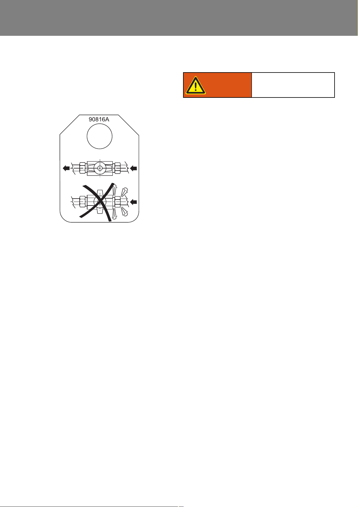
Thermo 230 / 231 / 300 / 301 / 350 8 Servicing
Information label
Danger to life and health!
Warning!
When installing a shut-off device in the return line a clearly
visible information label must be provided.
ATTENTION:
Operation with the return line shut off causes damage
to the fuel pump. Fuel may escape. Danger of fire.
8.6.3 Combustion Air Supply
Observe official regulations concerning the installation (see 1.6).
Combustion air must under no circumstances be
extracted from rooms with persons.
ATTENTION:
The combustion air inlet must not point towards the
forward direction of motion.
It must be located so that no clogging by contamination, impact of snow, or intake of splash water is to be
expected.
The combustion air intake and exhaust outlet is to be
located so that no air pressure difference builds up in
any operating condition of the vehicle.
Permissible dimensions of combustion air intake line:
• inner diameter: 55 mm
• max. length: 5 m
• max. bend: 270°
Loose fuel lines must be secured in order to avoid
sagging.
The installation of an additional fuel pump is not allowed.
Fuel lines permissible dimensions:
• inner diameter for suction and return line:
• 6 mm (other diameters upon request).
• max. permissible length for each suction and return
line: 10 m
• Max. permissible suction height: 2 m
• Max. permissible priming pressure: 0.3 bar for suction
and return line.
8.6.2.2 Fuel Filter
A by Spheros supplied with or approved fuel filter is to be
installed. Installation position possibly vertical with horizontal direction of flow.
To avoid operating malfunctions replace filter or filter cartridge once a year or more often if fuel is contaminated.
The combustion air inlet must be located so that no
exhaust fumes can enter.
NOTE:
If the combustion air intake line cannot be routed
upwards, a water drain hole Ø 4 mm is to be provided at
the lowest point.
If the heater is located near the fuel tank in a common
installation compartment, combustion air must be taken
in from and the exhaust routed to the exterior. The feedthroughs must be sealed against splash water.
If the heater is located in a closed installation box, a vent
port is required:
Thermo 230, 231, 300 and 301 30 cm
Thermo 350 35 cm
If the temperature in the installation box exceeds the
permitted ambient temperature of the heater (see
Technical Data), the vent port must be enlarged consulting Spheros.
2
2
806

Thermo 230 / 231 / 300 / 301 / 350 8 Servicing
Danger to life and health!
Warning!
Risk of scalding!
Caution!
8.6.4 Exhaust Line
Observe official regulations concerning the installation (see 1.6).
ATTENTION:
The exhaust pipe outlet opening must not point in the
direction of motion.
The exhaust pipe outlet opening must be located so
as not to expect clogging by snow or mud.
The combustion air intake and exhaust outlet is to be
located so that no air pressure difference builds up in
any operating condition of the vehicle.
Rigid pipes made of unalloyed or alloyed steel with a minimum wall thickness of 1.0 mm have to be used as exhaust
line or flexible pipes made of alloyed steel only. The
exhaust pipe is secured to the air heater e.g. with a clamp.
4. Loosen fuel supply and return line connections,
disconnect and fit dummy plugs.
Close water cocks as applicable.
5. Loosen hose clamps on coolant hoses, disconnect
hoses and fit dummy plugs.
6. Remove 3 screws and washers or 4 screws and
washers.
7. Remove heater.
8.7.1.2 Installation
1. Locate heater for installation and secure with 3 screws
and washers or 4 screws and washers.
2. Secure line on exhaust outlet using clamp.
3. Slide on coolant hoses and fasten with hose clamps.
Torque clamps with 1.5 Nm. Open water cocks.
4. Connect fuel supply and return lines and tighten
connections.
5. Secure combustion air inlet line on heater as
applicable.
6. Connect electrical connectors of cable harness in
vehicle and to circulation pump.
7. Bleed fuel supply system.
8. Bleed coolant circuit.
Permissible exhaust line dimensions:
– inner diameter: 70 mm
– max. length: 5 m without combustion air intake exten-
sion line
– max. bend: 270°
As an alternative an exhaust deflector must be installed
approved by Spheros.
8.7 Removal and Installation
CAUTION
In installed condition only the following disassembly or
removal procedures are permitted should enough space
for removal allow such action:
– replacement of temperature limiter
– replacement of temperature sensor
– replacement of combustion air fan
– replacement of burner
– replacement of igniter box
– replacement of flame sensor
– replacement of combustion chamber
8.7.2 Temperature Limiter, Replacement
NOTE:
The replacement procedure for the temperature limiter is
identical with the heater installed or removed.
Perform replacement in accordance with 9.2.1.
8.7.3 Temperature Sensor, Replacement
NOTE:
The replacement procedure for the temperature sensor is
identical with the heater installed or removed.
Perform replacement in accordance with 9.2.2.
Prior to replacement of temperature sensor in installed condition relief overpressure in cooling
system by opening the cooling circuit sealing
element.
If required also allow heater to cool down and have
collector vessel ready to collect escaping coolant.
8.7.1 Heater, Removal and Installation
8.7.1.1 Removal
1. Disconnect connectors of cable harness in vehicle
and of circulation pump.
2. Disconnect combustion air intake on heater if
required.
3. Loosen clamp on exhaust outlet.
807

Thermo 230 / 231 / 300 / 301 / 350 8 Servicing
High voltage!
Danger to life!
Warning!
High voltage!
Danger to life!
Warning!
High voltage!
Danger to life!
Warning!
High voltage!
Danger to life!
Warning!
8.7.4 Burner, Replacement
NOTE:
The replacement procedure for the burner is identical with
the heater installed or removed.
Perform replacement in accordance with 9.2.3.
The igniter box operates on high voltage. Prior to replacement of burner disconnect electrical connectors
of cable harness in vehicle to avoid lethal accidents.
8.7.5 Igniter Box, Replacement
NOTE:
The replacement procedure for the igniter box is identical
with the heater installed or removed.
Perform replacement in accordance with 9.2.8.
The igniter box operates on high voltage. Prior to replacement of burner disconnect electrical connectors
of cable harness in vehicle to avoid lethal accidents.
8.7.6 Flame Sensor, Replacement
NOTE:
The replacement procedure for the flame sensor is identical with the heater installed or removed.
Perform replacement in accordance with 9.2.9.
8.8 First Operation
After heater installation the coolant circuit and the fuel
supply system must be thoroughly bled observing the
vehicle manufacturer’s instructions. During test runs all
coolant and fuel line connections have to be checked for
security and no leakage. Should the heater in operation
enter a fault condition, perform troubleshooting (refer to
Section 5).
NOTE:
Heaters with control unit 1572D:
If the heater performs 5 subsequent attempts to start due
to a malfunction, the heater enters an error lockout and
stops any further attempts to start. This error lockout is
superior to the normal error lockout condition.
The error lockout reset is achieved by switching the heater
on and disconnection of the heater power supply within
120 sec. during run-down.
8.8.1 Water Circuit, Bleeding
NOTE:
Bleeding must always be performed in accordance with
manufacturer’s instructions. For bleeding the circulation
pump must not be switched on.
Set vehicle own heating system to "warm" and replenish
coolant which must consist of at least 30 % anti-freeze
(on glycol base) (protection against corrosion). When
using pure water there will be no protection against
corrosion and due to the lower boiling point of the water
when overheating loss of cooling water may result
requiring continuous replenishment. Additives in the
coolant must not affect metals, plastics or rubber and
leave no deposits.
The igniter box operates on high voltage. Prior to replacement of burner disconnect electrical connectors
of cable harness in vehicle to avoid lethal accidents.
8.7.7 Combustion Chamber, Replacement
NOTE:
The replacement procedure for the combustion chamber
is identical with the heater installed or removed.
Perform replacement in accordance with 9.2.11.
The igniter box operates on high voltage. Prior to replacement of burner disconnect electrical connectors
of cable harness in vehicle to avoid lethal accidents.
Then operate engine at increased idle until radiator
thermostat opens. Shut down engine, check coolant level
and replenish as required.
Switch on heater and vehicle heating fan with engine shut
down. After a certain cool-down period the heater must
automatically switch on and control to off. In case of no
restart attempt the temperature limiter on the heater has
responded because the heater has not been bled
properly. Reset temperature limiter (push button on
temperature limiter) and repeat complete bleeding
procedure.
NOTE:
The heater may be equipped with an automatically
resetting temperature limiter. The manual reset is not
necessary.
808

Thermo 230 / 231 / 300 / 301 / 350 8 Servicing
8.8.2 Fuel Supply System, Bleeding
The whole fuel supply system including the fuel filter must
completely filled with fuel before initial start-up.
NOTE:
Never use the fuel pump to fill / bleed the fuel system!
ATTENTION:
In the event no fuel comes to the fuel pump during
initial start-up, there is a risk that the fuel pump will be
damaged!
809

Thermo 230 / 231 / 300 / 301 / 350 9 Repair
9 Repair
9.1 General
This section describes the repairs that may be performed
on the heaters Thermo 230, 300 and 350 when removed.
Any further disassembly will void the warranty.
For re-assembly only components of the proper spare part
kits are to be used.
The following components may also be replaced with the
heater installed unless restricted space prevents access:
– temperature limiter
– temperature sensor
– combustion air fan
– burner
– igniter box
–flame sensor
– combustion chamber
NOTE:
Symbol tightening torque value:
Identifies in graphics parts (eg nuts, bolts)
that are to be mounted with a specific tightening torque. The torque values are shown
at the symbol and are binding.
901

Thermo 230 / 231 / 300 / 301 / 350 9 Repair
9.1.1 Work on Components after Disassembly
ATTENTION:
All gaskets located between disassembled components must always be replaced and discarded.
9.1.1.1 Visual Inspection, General
• Examine all components for damages (cracks,
deformation, wear, etc.) and replace as necessary.
• Examine connectors and wiring for corrosion, loose
contacts, wrong crimping, etc. and repair as
necessary.
• Check terminals for corrosion and contacts for
security. Repair as required.
9.1.1.2 Combustion Chamber, Visual Inspection
– Check swirl ring for security.
– Inspect combustion chamber for oxidizing and coke
deposits and remove as required.
– Check welding seem for cracks.
NOTE:
Longitudinal cracks up to 80 mm are allowed.
9.1.2 Incorporation of Modifications
NOTE:
Continuous enhancement of heater design is for optimizing performance and avoiding failures and malfunctions.
Normally equipment in use may be retrofitted using
available modification kits.
The following modifications may be incorporated during
repair procedures:
• installation of control unit 1572D as substitute for
control unit 1572 (see 9.1.2.1)
9.1.1.3 Heat Exchanger, Visual Inspection
– Inspect exhaust ducting in heat exchanger for sooting,
deposits, damage and corrosion.
NOTE:
Deposits are to be removed with water jet and brush.
– Inspect heat exchanger for exterior damage, defor-
mation, etc.
NOTE:
Heavy deformation may cause restricted flow of coolant.
ATTENTION:
When replacing the combustion chamber on
heaters installed vertically, remove deposits in heat
exchanger using a suitable tool.
9.1.1.4 Combustion Air Fan Wheel, Visual Inspection
– Check fan wheel for contamination and cracks.
– Check cover plate for security.
– Check slide lock for proper sealing.
902

Thermo 230 / 231 / 300 / 301 / 350 9 Repair
Control unit 1572D
Control unit 1572
Thermo label
Igniter box
9.1.2.1 Installation of Control Unit 1572D as
Substitute for Control Unit 1572
General
Due to the progress in the development of processors
control unit 1572 can no longer be supplied.
The retrofit of control unit 1572D is performed according
to the following procedure:
The modification kit consists of:
• control unit 1572D
• igniter box
• thermo identification label
Procedure
ATTENTION:
Control unit 1572D may only be used in combination
with the igniter box delivered (green connector
cover). The electrical connector is coded.
1. Remove control unit according to 9.2.5.1 and
discard.
2. Remove igniter box according to 9.2.8.1 and
discard.
3. Install new igniter box according to 9.2.8.2.
4. Install new control unit according to 9.2.5.2.
5. Apply new thermo label onto existing label to indicate
retrofit.
903

Thermo 230 / 231 / 300 / 301 / 350 9 Repair
Risk of scalding!
Caution!
9.2 Disassembly and Assembly
9.2.1 Temperature Limiter, Replacement
9.2.1.1 Removal
1. Disconnect electrical connection to temperature
limiter.
2. Withdraw rubber cap. Using screw driver lever off
retaining spring and remove temperature limiter
(1, Fig. 901).
9.2.1.2 Installation
1. Slide rubber cap of temperature limiter (1, Fig. 901)
back until temperature limiter can be located for
installation.
2. Position temperature limiter (1) in connector (3) and
push in retaining clip.
ATTENTION:
The retaining spring must be located in the groove of
the housing and must be latched in position both
perceptibly and audibly (twice) at the collar of the
locating socket. Only then will the temperature limiter
be in proper contact with the heat exchanger jacket.
2. Unscrew temperature sensor (2, Fig. 901) and
remove.
9.2.2.2 Installation
1. Manually screw temperature sensor (2, Fig. 901) into
coolant outlet (4).
2. Tighten temperature sensor.
3. Restore electrical connections.
NOTE:
Observe electrical wiring color coding when making
connections to temperature sensor.
9.2.3 Burner, Replacement
9.2.3.1 Removal
1. Disconnect electrical connections on burner and
loosen fuel lines.
2. Loosen nuts (6, Fig. 901) until hinge bolts are free.
3. Swing hinge bolts (7) open and remove cotter pin (5).
4. Remove burner (8).
5. Perform procedures on components after
disassembly (refer to 9.1.1).
3. After the rubber cap has been placed in position, the
cable must be aligned in the cable sleeve, free from
strain.
Connection cables must not be routed over reset
button.
NOTE:
Observe electrical wiring color coding when making
connections to temperature limiter.
4. Make electrical connections.
9.2.2 Temperature Sensor, Replacement
9.2.2.1 Removal
1. Disconnect electrical connection to temperature
sensor.
9.2.3.2 Installation
1. Position burner (8, Fig. 901) for installation, swing
hinge bolts closed and secure temporarily using
screws (6).
2. Insert cotter pin (5) according to the intended opening
swing direction.
3. Tighten nuts (6).
4. Connect fuel lines.
5. Restore electrical connections.
NOTE
Observe electrical wiring color coding when making
connections to temperature limiter and temperature
sensor.
Prior to replacement of temperature sensor in installed condition relief overpressure in cooling system by opening the cooling circuit sealing element.
If required also allow heater to cool down and have
collector vessel ready to collect escaping coolant.
904

Thermo 230 / 231 / 300 / 301 / 350 9 Repair
Rubber cap
Temperature
Retaining clip
8
7
6
5
4
3
2
1
1 Temperature limiter
2 Temperature sensor
3 Connector
4 Coolant outlet
5 Cotter pin
6 Nut (2)
7 Hinge bolt (2)
8 Burner
limiter
NOTE
Cotter pin (5) may be fitted on other side as required for
burner head to swing open in opposite direction.
20 +5 Nm
7.5 +1 Nm
Fig. 901 Temperature Limiter, Temperature Sensor and Burner, Replacement
905

Thermo 230 / 231 / 300 / 301 / 350 9 Repair
Closing slide lockOpening slide lock
9.2.4 Combustion Air Fan, Replacement
NOTE:
For replacement of the combustion air fan the burner may
be left installed.
In removed condition ensure that igniter electrodes are
not bent and nozzle is not damaged.
9.2.4.1 Removal
1. Loosen screws (3, Fig. 902) and withdraw cap (2)
from burner.
2. Using suitable tool (e.g. mandrel 3 mm) open slide
lock (5) until fan wheel can be pulled off.
3. Disconnect electrical connector (9).
4. Remove screws (6) with lock washers and withdraw
fan motor (7).
5. Perform procedures on components after
disassembly (refer to 9.1.1).
9.2.4.2 Installation
NOTE:
Fan motor (7, Fig. 902) to be aligned with control unit
(recess in mounting flange) and with clutch (by rotating
drive shaft).
1. Align fan motor (7) and position for installation.
2. Attach fan motor using screws (6) and lock washers.
3. Tighten screws.
4. Connect electrical connector (9).
5. Bring slide lock (5) on fan wheel in installation
position.
6. Slide fan wheel onto drive shaft and using suitable tool
(e.g. mandrel 3 mm or pliers) close slide lock until fan
wheel is locked.
7. Locate cap (2) and secure with screws (3).
8. Tighten screws.
906

Thermo 230 / 231 / 300 / 301 / 350 9 Repair
1
2
3
4
56
7
8
9
1 Splash protection cover
2 Cap
3 Screw (2)
4 Fan wheel
5 Slide lock
6 Screw (3)
7 Fan motor
8 Clutch
9 Electrical connector
5 +1 Nm
2 Nm
Fig. 902 Combustion Air Fan, Replacement
907

Thermo 230 / 231 / 300 / 301 / 350 9 Repair
High voltage!
Danger to life!
Warning!
9.2.5 Control Unit, Replacement
NOTE:
For replacement of the control unit the burner head
may be left installed and must only be swung open for
disconnection of electrical connector (8, Fig. 904).
In removed condition ensure that igniter electrodes are
not bent and nozzle is not damaged.
If a control unit 1572 is substituted with a control unit
1572D, perform procedure according to 9.1.2.1.
9.2.5.1 Removal
1. Disconnect all electrical connections from control unit
(23, Fig. 904).
2. Swing burner head open (refer to 8.5.2) and
disconnect electrical connector (8).
3. Remove flame sensor (refer to 9.2.9.1).
4. Remove combustion air fan (refer to 9.2.4.1).
5. Carefully withdraw control unit (23) in axial direction
from burner head (17) and remove.
6. Perform procedures on components after
disassembly (refer to 9.1.1).
9.2.5.2 Installation
1. Carefully push control unit (23, Fig. 904) in axial
direction against stop into burner head (17).
2. Install combustion air fan (refer to 9.2.4.2).
3. Make all electrical connections on control unit (23).
4. Install flame sensor (refer to 9.2.9.2).
5. Connect electrical connector (8).
9.2.6 Fuel Pump, Replacement
9.2.6.1 Removal
1. Remove burner (refer to 9.2.3.1).
2. Using screwdriver lever off igniter electrodes
(3, Fig. 904) from igniter box (1) and remove.
3. Remove disc (6) with heating cartridge (if installed).
4. Disconnect electrical connector (8).
9.2.6.2 Installation
1. Install solenoid valve (7, Fig. 904) on fuel pump (10)
if required.
2. Fit new O-rings (12) and filter screen (11) on fuel
pump (10).
3. Position fuel pump (10) for installation and secure
with new screws (9) (with threadlock coating).
4. Tighten screws.
5. Connect electrical connector (8).
6. Plug on disk (6) and mount heating cartridge.
7. Plug on igniter electrodes (3).
8. Install burner (refer to 9.2.3.2).
9.2.7 High Pressure Nozzle, Replacement
9.2.7.1 Removal
1. Remove burner (refer to 9.2.3.1).
2. Using screwdriver lever off igniter electrodes (3, Fig.
904) from igniter box (1) and remove.
3. Remove disk (6) with heating cartridge (if installed).
4. Disconnect electrical connector (8) of the heating
cartridge.
5. Unscrew high pressure nozzle (4).
NOTE:
Ensure cleanliness is maintained when installing the
nozzle. Only touch the nozzle at its hexagon surface.
9.2.7.2 Installation
1. Screw in high pressure nozzle (4, Fig. 904) and
tighten.
2. Connect electrical connector (8) of the heating
cartridge.
3. Plug on disk (6) and mount heating cartridge.
4. Plug on igniter electrodes (3).
5. Install burner (refer to 9.2.3.2).
9.2.8 Igniter Box, Replacement
NOTE:
During the following step ensure that escaping fuel is
immediately neutralized and properly disposed of.
5. Remove screws (9) and discard.
6. Withdraw fuel pump (10) together with solenoid valve
(7) and remove.
7. Remove and discard O-rings (12) and filter screen
(11).
8. Remove solenoid valve (7) from fuel pump (10) as
required.
9. Perform procedures on components after
disassembly (refer to 9.1.1).
The igniter box operates with high voltage. Prior to
opening the burner head the connectors of the cable
harness in the vehicle have to be disconnected to
prevent lethal injuries.
908

Thermo 230 / 231 / 300 / 301 / 350 9 Repair
1 Igniter box
2 Screw (2)
3 Igniter electrodes
4 High pressure nozzle
5 Viewing glass
6 Disk
7 Solenoid valve
8 Electrical connector
9 Screw (3)
10 Fuel pump
11 Filter screen
12 O-ring (2)
13 Rotating ring
14 Screw
15 Flame sensor
16 Screw
17 Burner housing
18 Strain relief clamp (2)
19 Screw (2)
20 Base plate
21 Relay
22 Relay
23 Control unit
24 Heating cartridge with
thermostat
25 Clip
26 Overheat thermostat
(Thermo Top 231 / 301 only)
only)
1
2
3
9
8
7
4
10
11
12
13
14
15
16
17
18
19
20
21
23
22
24
25
5
6
Control unit
23
1572
Control unit
1572D
5
6
8
Overheat
thermostat only
Thermo 231 / 301
26
20 Nm
5 +1 Nm
5 +1 Nm
5 +1 Nm
Fig. 903 Control Unit and Fuel Pump, Replacement
909
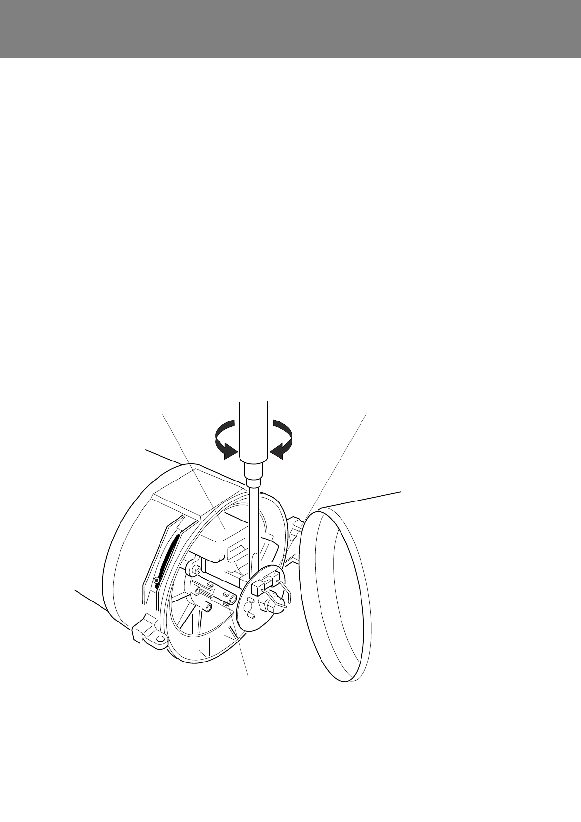
Thermo 230 / 231 / 300 / 301 / 350 9 Repair
Igniter box
Igniter electrodes
Removal and
installation of
igniter electrodes
Flame sensor
9.2.8.1 Removal
1. Remove burner if required (refer to 9.2.3.1).
2. Using screw driver lever off igniter electrodes
(Fig. 904) from igniter box and remove.
3. Remove disk (6).
4. Remove combination screws (2).
5. Withdraw igniter box (1) and remove.
6. Perform procedures on components after
disassembly (refer to 9.1.1).
9.2.8.2 Installation
1. Locate igniter box (1, Fig. 904) for installation, plug on
making correct electrical connections and secure with
combination screws (2).
2. Tighten combination screws (2).
3. Plug on disk (6) and align.
4. Plug on igniter electrodes (3).
5. Install burner (refer to 9.2.3.2).
9.2.9 Flame Sensor, Replacement
9.2.9.1 Removal
1. Remove burner if required (refer to 9.2.3.1).
2. If required lever off igniter electrodes (Fig. 904) from
igniter box using screw driver and remove.
3. Remove disk (6).
4. Remove screw (14) and lock washer.
5. Withdraw flame sensor (15) and remove.
6. Perform procedures on components after
disassembly (refer to 9.1.1).
9.2.9.2 Installation
1. Position flame sensor (15, Fig. 904) for installation,
plug on to make correct electrical connections and
secure with screw (14) and lock washer.
2. Tighten screw (14).
3. Plug on disk (6) and align.
4. Plug on igniter electrodes (3).
5. Install burner (refer to 9.2.3.2).
Fig. 904 Igniter Box and Flame Sensor, Replacement (Sheet 1 of 2)
910

Thermo 230 / 231 / 300 / 301 / 350 9 Repair
1 Igniter box
2 Screw (2)
3 Igniter electrodes
4 High pressure nozzle
5 Viewing glass
6 Disk
7 Solenoid valve
8 Electrical connector
9 Screw (3)
10 Fuel pump
11 Filter screen
12 O-ring (2)
13 Rotating ring
14 Screw
15 Flame sensor
16 Screw
17 Burner housing
18 Strain relief clamp (2)
19 Screw (2)
20 Base plate
21 Relay
22 Relay
23 Control unit
24 Heating cartridge with
thermostat
25 Clip
26 Overheat thermostat
(Thermo Top 231 / 301 only)
only)
1
2
3
9
8
7
4
10
11
12
13
14
15
16
17
18
19
20
21
23
22
24
25
5
6
Control unit
23
1572
Control unit
1572D
5
6
8
Overheat
thermostat only
Thermo 231 / 301
26
20 Nm
5 +1 Nm
5 +1 Nm
5 +1 Nm
Fig. 904 Igniter Box and Flame Sensor, Replacement (Sheet 2 of 2)
911

Thermo 230 / 231 / 300 / 301 / 350 9 Repair
Position of the welding seam
Position of the cut-outs in the combustion
chamber head when installed
when installed
Cut-outs
o.k.
Not permitted!
1
2
9.2.10 Heat Exchanger, Replacement
9.2.10.1 Removal
1. Remove temperature limiter (refer to 9.2.1.1).
2. Remove temperature sensor (refer to 9.2.2.1).
3. Remove burner (refer to 9.2.3.1).
4. Withdraw combustion chamber (1, Fig. 905) from heat
exchanger (2).
5. Remove heat exchanger (2).
6. Perform procedures on components after
disassembly (refer to 9.1.1).
9.2.10.2 Installation
1. Install combustion chamber (refer to 9.2.11.2).
2. Install burner (refer to 9.2.3.2).
3. Install temperature limiter (refer to 9.2.1.2).
4. Install temperature sensor (refer to 9.2.2.2).
9.2.11 Combustion Chamber, Replacement
9.2.11.1 Removal
1. Disconnect electrical connections to temperature
limiter and temperature sensor.
2. Swing burner open (refer to 8.5.2).
3. Withdraw combustion chamber (1, Fig. 905) from heat
exchanger (2) and remove.
4. Perform procedures on components after
disassembly (refer to 9.1.1).
Fig. 905 Heat exchanger and combustion chamber replacement
912

Thermo 230 / 231 / 300 / 301 / 350 9 Repair
9.2.11.2 Installation
ATTENTION:
When replacing the combustion chamber, ensure that
the new combustion chamber corresponds to the
heating capacity class of your heating appliance.
1. Slide combustion chamber (1, Fig. 905) fully into the
heat exchanger (2) against stop. Pay attention to
a) the welding seam position, and
b) the position of cut-outs in the combustion chamber
head
NOTE:
– The combustion chamber should be inserted into the
heat exchanger in such a way that its welding seam is
positioned between 2 and 10 o clock (not upwards!)
(Fig. 905). A position change during maintenance is
permissible and affects the expected service life of the
combustion chamber positively.
– Position the cut-outs in the combustion chamber head
as shown in Fig. 905.
Dripping from nozzle fuel is so collected in a reservoir
between disc and burner head and will be burned at
the next burner operation instead to soil the heater.
2. Swing burner closed (refer to 8.5.2).
NOTE:
Observe electrical wiring color coding when making
connections.
3. Make electrical connections to temperature limiter and
to temperature sensor.
913

Thermo 230 / 231 / 300 / 301 / 350 10 Packaging, Storage and Shipping
10 Packaging, Storage and
Shipping
10.1 General
The heater or its components shipped to Webasto
Thermosysteme GmbH for testing or repair must be
cleaned and packaged so that they are protected against
damage during handling, shipping and storage.
CAUTION
When shipping a complete heater assembly it must be
drained completely. No coolant is allowed to escape when
packaging or shipping.
Dummy plugs must be fitted to the coolant inlet and outlet
as well as to the fuel lines.
In storage the ambient temperatures specified in
Section 4 must not be exceeded.
1001

Maintenance plan
Address of the operator Date of maintenance
Vehicle data
Heater data
Type of heater: Operating/ control device data
Fuel
Diesel fuel
Biodiesel
Date of commision
Heating oil EL
Ident. no.:
Serial no.:
acc. to diagnosis STT
(Spheros Thermo Test)
for heaters of type Thermo, Thermo E, Thermo S and Thermo
plus in buses und railway vehicles
Periodic heater maintenance
The heater should be inspected in periodic time intervals,
latest at the beginning of the heating period (time of increased heater usage due to present weather conditions).
In principle the regulations of the vehicle manufacturers
as well as the relevant regulations of the German Federal
Railway Authority (EBA) and its technical service must be
adhered. If there no such regulations, Valeo prescribes
the here shown maintenance intervals for common
applications. For the execution of the work, the corresponding workshop manual is to be used.
If heaters should be used in other vehicles and/or applications, the maintenance intervals may be shortened or
extended. In such cases please contact your dedicated
Valeo partner for further information.
Check / Maintenance Important notes Check result Measured values,
1. Electrical connections
a) Examine electrical plug connections and the wiring harness
for visible damages, replace as required.
2. Heat exchanger
a) Check for external damage, discoloration caused by over-
heating and leaks.
b) Clean the heat exchanger inside and outside, remove soot
and debris.
3. Fuel system
a) Inspect fuel lines and connections for leakage.
b) Replace fuel filter insert with gasket. resp. replaceable filter.
Determine overheating
cause as needed (e.g.
water circulation system), check overheat
protection.
Ensure connections to
fuel flow and return
lines are sealed tight!
If biodiesel is used a
semi annual filter
change is prescribed by
the manufacturer.
Re-tighten screw connections and hose
clamps.
Änderungen vorbehalten. Für Übersetzungen ist die deutsche Fassung rechtlich bindend. Die aktuelle Fassung dieses Dokumentes steht unter
www.valeo-thermalbus.com zum Download bereit. / Subject to modification. For translations the german version is binding. Latest version of
this document is provided for download on www.valeo-thermalbus.com.
OK not
OK
accomplished repairs
A-1

Maintenance plan
for heaters of type Thermo, Thermo E, Thermo S and Thermo
plus in buses und railway vehicles
Check / Maintenance Important notes Check result Measured values,
OK not
OK
accomplished repairs
c) Fuel pump / fuel lines
Note: Observe technical information if biodiesel
or FAME is used!
d) Replace fuel screen with gasket in the pump.
4. Burner head
a) Inspect combustion air intake opening for clear passage.
b) Inspect hood for damage.
c) Clean flame detector inspection glass (in the disk).
d) Inspect condition of the ignition electrodes, if required adjust
or replace them.
e) Replace atomiser nozzle.
f) Check solenoid valve for leaks.
5. Exhaust system
a) Inspect exhaust line for clear passage or damage, clean or
replace it as needed.
b) Remove combustion chamber from heat exchanger, inspect
for damage and contamination, clean and replace as
needed.
c) Insert combustion chamber and mount burner head. Ensure
proper fit and tight connection to the heat exchanger.
Replace the fuel pump
every 5 years, if biodiesel is used this interval
is shortened
Technical Information
Biodiesel / FAME
see www.valeo-
thermalbus.com
Replace damaged
parts.
Activate combustion air
motor using the diagnostic tool (STT),
solenoid valve must be
tight
d) Combined nuts (M8) for burner head attachment, tightening
torque 7.5 +1 Nm, secure them.
e) Measurements
Target values and procedures are outlined in the workshop
manual
Ambient temperature (° C)
Exhaust temperature (° C)
(Vol.-%) at 24V
CO
2
Thermo plus 230
Thermo plus 300/350
CO
Smoke spot number acc. to Bacharach (all devices)
Fuel pump pressure according to Workshop Manual
Thermo, Thermo S
Thermo E 200, Thermo plus
6. Water system
a) If available, inspect, clean as needed or replace water filter
insert.
Thermo
Thermo E 200
Thermo E 300
Thermo S
(ppm) at 19V
2
Rail versions
Thermo E 320
Secure them with
locking compound
Limits acc. to Regulation ECE-R 122
see technical data
heater
10 ±0.5
9.5 ±0.5
10.0 ±0.5
9.5 +1.5
9.0 +1.5
9.5 +1.5
_<1000
_< 4
10 bar
8 +1 bar
9 +1 bar
A-2

Maintenance plan
for heaters of type Thermo, Thermo E, Thermo S and Thermo
plus in buses und railway vehicles
7. Functional check
a) If available, open shut-off valve of the fuel return line and
water line.
b) Check fault memory, clear it as needed using the diagnostic
tool (STT).
c) Check heater functionality.
Attention:
During the maintenance, check all screw connections for tightness (for corresponding torque values see Workshop Manual).
after at least 10 min
heater operation
A-3

memos

Valeo Thermal Commercial Vehicles Germany GmbH
Postfach 1371 - 82198 Gilching - Germany - Tel. +49 (0)8105 7721-0 - Fax +49 (0)8105 7721-889
www.valeo-thermalbus.com - service-valeobus@valeo.com
 Loading...