


Rev. 21.11.2018
Id.No. DOK30629
BUS BODY ELECTRONICS
SC600 REVO GLOBAL
Operating Instructions
- Busdriver

BUS BODY ELECTRONICS
1
Contents
Contents 1
List of Figures 2
List of Tables 2
1 Introduction 3
1.1 Intended purpose 3
1.2 Symbols used 3
1.3 Description of the dashboard 4
1.4 Description of the display screen 4
1.5 Overview of modes 5
2 Operation 6
2.1 Switching on/off 6
2.1.1 Switching on 6
2.1.2 Switching off 6
2.2 Auto mode 6
2.2.1 Activation 6
2.2.2 Deactivation 6
2.3 Setting the blower manually 7
2.3.1 Activating the manual adjustment 7
2.3.2 Set blower level 7
2.4 Fresh air/circulation function 8
2.5 Dehumidification 8
2.6 Setting temperature 8
2.7 Faults 9
2.7.1 Fault readout mode 9
2.7.2 Fault overview 9

BUS BODY ELECTRONICS
2
List of Figures
Fig. 1 - SC600 dashboard ........................................................................................ 4
Fig. 2 - SC600 display screen ................................................................................... 4
Fig. 3 - SC600 Overview of modes ............................................................................. 5
Fig. 4 - SC600 Start display ...................................................................................... 6
Fig. 5 - SC600 auto mode is activated ......................................................................... 6
Fig. 6 - SC600 auto mode is activated, cooling mode ....................................................... 6
Fig. 7 - SC600 auto mode activated, heating mode .......................................................... 6
Fig. 8 - SC600 auto mode deactivated ......................................................................... 7
Fig. 9 - Manually adjusting SC600 blower level............................................................... 7
Fig. 10 - SC600 Circulation function activated ................................................................ 8
Fig. 11 - SC600 dehumidification is activated ................................................................. 8
Fig. 12 - adjusting SC600 temperature ......................................................................... 8
Fig. 13 - SC600 Faults ............................................................................................ 9
Fig. 14 - Entering SC600 access code ...................... Fehler! Textmarke nicht definiert.
Fig. 15 - Reading out SC600 faults ............................................................................. 9
Fig. 16 - Standard SC600 operating display .................................................................. 9
List of Tables
Table 1 - REVO GLOVAL fault overview .................................................................... 10

BUS BODY ELECTRONICS
3
1 Introduction
1.1 Intended purpose
The SC600 is a system for controlling HVAC components (heating, ventilation, air conditioning)
in buses as well as rooftop air conditioning units, heaters etc.
It consists of an operating element integrated into the dashboard (control device as humanmachine interface) and a rooftop air conditioning unit or floor heating. The rooftop A/C unit,
depending on the version, takes over ventilation, cooling and heating functions. In addition, air
conditioning components can be controlled completely automatically. In this case, the bus driver
only needs to set the desired temperature.
1.2 Symbols used
Note

BUS BODY ELECTRONICS
4
Fig. 2 - SC600 display screen
1.3 Description of the dashboard
The dashboard components are depicted and explained in the following graphic.
1.4 Description of the display screen
1. Display
2. On/off button
3. Scroll UP menu key
4. Scroll DOWN menu key
5. Function status light
6. Blower button
7. Fresh air/circulation air button
8. Auto button
A. Inside temperature target value
B. Manual blower level
C. Cooling mode
D. Heating mode
E. Circulation air on
F. Fault display
G. Auto mode active
H. Outside temperature
1
2
3
4
6
7
8
5
Fig. 1 - SC600 dashboard
B H C A D F G
E

BUS BODY ELECTRONICS
5
1.5 Overview of modes
The SC600 contains 2 different modes – the operating mode and the
fault mode.
Fig. 3 - SC600 Overview of modes
SC600
Operating mode:
Includes all of the
functions and notes
summarised under
point 2 except for
the fault readout
and refill mode.
The normal operating display includes
all of the elements
pictured in the ex-
ample:
Fault readout
mode
Mode for displaying
all of the occurring
faults and their frequency of occur-
rence.
For more infor-
mation, see points
2.6.1 and 2.6.2.
The normal fault
display includes all
of the elements pic-
tured in the example:

BUS BODY ELECTRONICS
6
2 Operation
2.1 Switching on/off
2.1.1 Switching on
Press button
➔ The temperature that was last set is now set; auto
mode on (Fig. 4)
2.1.2 Switching off
Press button
➔ System is switched off
2.2 Auto mode
2.2.1 Activation
Press button in deactivated mode
➔ Mode is activated - corresponding status light and
function symbol in display light up (Fig. 5)
2.2.2 Deactivation
Press button in activated auto mode
➔ Mode is deactivated - corresponding status light and
function symbol are off (Fig. 8)
Note
Switching on system takes place only when the ignition is
switched on.
Note
If the auto mode is activated, the system automatically
switches on cooling mode and heating mode as re-
quired (Fig. 6 and 7).
Fig. 4 - SC600 Start display
Fig. 5 - SC600 auto mode is activated
Fig. 6 - SC600 auto mode is activated,
cooling mode
Fig. 7 - SC600 auto mode activated,
heating mode

BUS BODY ELECTRONICS
7
2.3 Setting the blower manually
2.3.1 Activating the manual adjustment
Press button
➔ Manual operation of the blower is activated - the
blower continues running at the current speed.
➔ 3 seconds after the blower level button is pressed, the
blower level can be manually adjusted (during this period, the corresponding status light flashes).
2.3.2 Set blower level
The blower can be set to various levels from 0 (blower speed = 0%) to 10 (blower speed =
100%).
Press button
➔ Blower level +1 ( → ).
Press button
➔ Blower level -1 ( → ).
Note
When auto mode is deactivated, the A/C compressor and
heater will switch off (the former after a max. after-run period
of 90 secs).
The blower is automatically adjusted if the blower level is not
set automatically.
Note
Adjustment can be made within the permitted limits (e.g.,
motor off → blower speed max. 25 %)
If the blower is reduced to under 20%, cooling and heating
modes are deactivated.
Fig. 8 - SC600 auto mode deactivated
Fig. 9 - Manually adjusting SC600 blower
level

BUS BODY ELECTRONICS
8
Fig. 12 - adjusting SC600 temperature
2.4 Fresh air/circulation function
Press button
➔ System switches on fresh air/circulation for 10
minutes (i.e., if the fresh air function is currently active, the system switches to the circulation function
and vice versa).
➔ After operating for 10 minutes, the system switches
the function that best supports reaching the desired
temperature.
➔ Pressing the button again within 10 minutes leads to
switching the function and resetting to 10 minutes.
2.5 Dehumidification
Press button for 2 seconds
➔ Air dehumidification activated (Fig. 11).
2.6 Setting temperature
Press button
➔ Target temperature +1 °C
Press button
➔ Target temperature -1 °C
Note
If the fresh air flaps are closed, the corresponding status light
lights up (Fig. 10).
Note
The temperature can be adjusted in 1 °C steps between 15
°C and 28 °C.
Fig. 10 - SC600 Circulation function
activated
Fig. 11 - SC600 dehumidification is
activated
BUS BODY ELECTRONICS
9
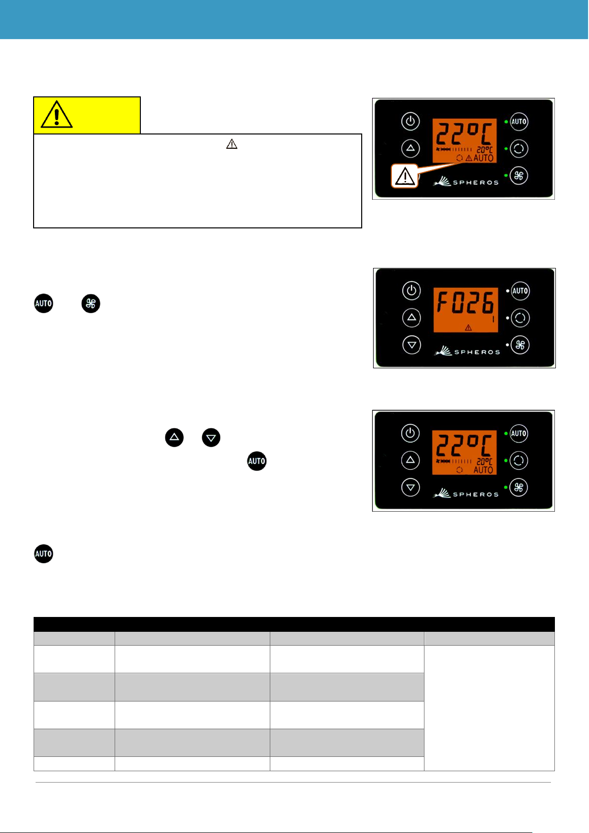
2.7 Faults
2.7.1 Fault readout mode
2.7.1.1 Activation
and Press buttons simultaneously for 2 seconds
➔ Mode is activated; the fault code (in this case F026)
and the frequency of occurrence count (in this case
1) will be displayed (Fig. 14).
2.7.1.2 Reading out faults
➔ When the code is correctly enteredScroll through the
fault codes with or .
➔ Reset the counter value with (if the counter
shows "1" after the value is reset, the fault is still present).
2.7.1.3 Quitting
Press button for 2 seconds
➔ Standard operating display appears (Fig. 15).
2.7.2 Fault overview
Fault code
Component
Cause
Remedy
F001
Operating element
➢ Internal fault
➢ Replace ECU
F017
Ice sensor
➢ Sensor defective
➢ Cable harness defective
➢ Examine cable har-
ness
➢ Replace sensor
F018
Duct temperature sensor
➢ Sensor defective
➢ Cable harness defective
F019
Interior temperature sensor
➢ Sensor defective
➢ Cable harness defective
F020
Ambient temperature sensor
➢ Sensor defective
➢ Cable harness defective
F021
Floor temperature sensor
➢ Sensor defective
Note
When active faults are present, the function symbol in the
display flashes (Fig. 13).
The warning symbol is not displayed for inactive/saved
faults. In order to view inactive faults, it is necessary to
switch to fault readout mode.
Fig. 13 - SC600 Faults
Fig. 14 - Reading out SC600 faults
Fig. 15 - Standard SC600 operating
display

BUS BODY ELECTRONICS
10
Fault code
Component
Cause
Remedy
➢ Cable harness defective
F022
Condenser pressure sensor
➢ Sensor defective
➢ Cable harness defective
F025
High pressure
Low pressure
➢ Coolant level too high
➢ Blower blocked
➢ Blower outage
➢ Condenser pressure
sensor defective
➢ Coolant level too low
➢ Solenoid valve defective
➢ Pressure switch defec-
tive
➢ Expansion valve defec-
tive
➢ Examine axial blo-
wer
➢ Check coolant filling
level
➢ Examine sensors
➢ Check for leaks
➢ Replace solenoid
valve
➢ Replace pressure
switch
➢ Replace expansion
valve
F026
Ice sensor
➢ Icing
➢ Temperature too low
➢ Wait until sensor is
thawed out
F033
Configuration fault
➢ Incompatible parameters
selected
➢ Change correspon-
ding parameters
Table 1 - REVO GLOVAL fault overview

Valeo Thermal Commercial Vehicles Germany GmbH
Postfach 1371 – 82198 Gilching - Germany - Tel. +49 (0)8105 7721-0 - Fax 49 (0)8105 7721-889
www.valeo-thermalbus.com - service-valeobus@valeo.com
 Loading...