

Page 1

AIR CONDITIONING
REVO®-E Heat pump
Volvo
Workshop Manual
Rev. 06/2019
Id.No. 11123006A
Page 2

REVO-E Heat pump Content
1 Introduction
1.1 Content and purpose 101
1.2 Validity of the workshop manual 101
1.3 Meaning of emphasis 101
1.4 Symbols 101
1.5 Additional documentation to be used 101
1.6 Safety information and condition 101
1.6.1 General safety information 102
1.6.2 Working with high-voltage air-conditioning systems 102
1.6.3 Working with refrigerants 102
1.6.4 Working with pressurized containers 103
1.6.5 Technical rules for pressurized gases (TRG) 103
1.6.6 Waste and residual materials 103
1.7 Suggestions for improvement and change 103
1.8 Abbreviations 104
2 Technical specifications
3 Description of assemblies and components
3.1 REVO-E HP versions on the Volvo 79xx Electric 301
3.2 Total overview of the design and components of the REVO-E heat pump 302
3.3 Overview of high-voltage cable harnesses / components (400V AC / 600V DC) 303
3.4 Cable harnesses overview (high-voltage / low-voltage) in the REVO-E HP 304
3.5 Design / task and function of the assemblies 305
4 Function and functional schematics of the REVO-E Heat pump
4.1 General function 401
4.2 Functional schematic of the REVO-E heat pump 402
4.3 Functional schematic of the REVO-E heat pump Volvo 7900 Electric 403
4.4 Work modes of the REVO-E heat pump in the Volvo 7900 Electric 404
4.4.1 Heating and Ventilation Mode (HV Mode) 405
4.4.2 Heating and Ventilation Mode Ready for cooling 406
4.4.3 Heating and Ventilation Mode Ready for Heat Pump Mode 407
4.4.4 Cooling Mode 408
4.4.5 Heat Pump Mode 410
4.4.6 Operating Mode De-Icing) (Version HP+ only) 412
4.4.7 Operating Mode Oil Recovering (Version HP+ only) 413
4.4.8 Reheat Mode 414
4.4.9 Waste Energy Mode 415
4.4.10 Gas Charging Mode 416
4.5 Refrigerant circuit function schematic of the heat pump 417
4.5.1 Refrigerant circuit function schematic of the heat pump in the Cooling Mode 418
4.5.2 Refrigerant circuit function schematic of the heat pump in the Heat Pump Mode 419
4.5.3 4-way reversing valve function schematic 420
4.5.4 Refrigerant circuit function schematic of the heat pump with hot gas de-icing (
11123865_ only) 422
5 Troubleshooting
5.1 General 501
5.2 Malfunctions in the air-conditioning circuit 501
5.2.1 Causes of malfunctions in the air-conditioning system 501
5.2.2 What to do for malfunctions in the refrigerant circuit 501
5.2.3 Why the desired conditions are not reached when testing pressure 501
1
Page 3

REVO-E Heat pump Content
5.3 Malfunctions in the electrical system 501
5.4 Table of error codes 503
5.5 Error codes 504
5.6 Inspecting functionality of individual components 509
5.6.1 General visual inspection 509
5.7 Diagnosing the REVO-E units using the Diagnosis Control Test – DCT diagnostic software 509
5.8 Diagnosing the frequency converter 509
6 Wiring diagrams
6.1 Electrical fuses 601
6.2 Wiring diagram REVO-E HP (11120816*) 601
6.3 Wiring diagram REVO-E HP+ (11123865*) 608
6.4 Frequency converter - electrical connections 615
6.4.1 600V DC power supply including HVIL connector 615
6.4.2 400V AC voltage output 616
6.4.3 PE connection (potential equalizing) 616
6.5 Compressor - electrical connections 617
6.5.1 400V AC voltage supply 617
6.5.2 PE connection (potential equalizing) 617
7 Maintenance
7.1 Safety information 701
7.2 Versions of ADA 701
7.3 Maintenance and upkeep 701
7.4 Inspection and maintenance 701
7.4.1 Changing the fresh air filter 701
7.4.2 Changing the filter dryer 701
7.4.3 Inspecting the oil level of the compressor 702
7.4.4 Changing the compressor oil 702
8 Removal and installation of components (high-voltage system)
8.1 Safety information 801
8.2 Versions of ADA 801
8.3 Preparation/follow-up 801
8.3.1 High-voltage system 801
8.3.2 Refrigeration section 801
8.4 Frequency converter removal/ inst alla tio n 802
8.4.1 Remove the frequency converter 802
8.3.2 Install the frequency converter 803
8.4 Refrigerant compressor removal/ installation 804
8.4.1 Remove the compressor 804
8.4.2 Comparing the old/new oil level 806
8.4.3 Install the compressor 806
8.5 600V DC/ 400V AC high-voltage cable removal/ installation 808
8.5.1 Remove the 600V AC cable 808
8.5.2 Install the 600V DC cable 808
8.5.3 Remove the 400V AC cable 808
8.5.4 Install the 400V AC cable 809
9 Removal and installation of components
9.1 Safety information 901
9.2 Versions of ADA 901
9.3 Preparation/follow-up 901
9.4 Condenser module removal/ installation 901
2
Page 4

REVO-E Heat pump Content
9.4.1 Removal of the condenser module 901
9.3.2 Installation of the condenser module 902
9.4 Expansion valves removal/ installation 903
9.4.1 Positions of the expansion valves and the associated contact sensors 903
9.4.2 Remove an expansion valve 904
9.4.3 Install an expansion valve 904
9.5 Filter dryer removal/ installation 905
9.5.1 Remove the filter dryer 905
9.5.2 Install the filter dryer 905
9.6 Receiver removal/ installation 905
9.6.1 Remove the receiver 905
9.6.2 Install the receiver 905
9.7 Double radial blowers / axial fans removal/ installation 906
9.7.1 Remove a double radial blower 906
9.7.2 Install a double radial blower 906
9.7.3 Remove an axial fan 906
9.7.4 Install an axial fan 906
9.8 Recirculating air flap actuator motor removal/ installation 907
9.8.1 Remove the actuator motor 907
9.8.2 Install the actuator motor 907
9.9 Temperature sensor (duct / recirculating air suction) removal/ installation 907
9.9.1 Remove the duct temperature sensor (blow-out temperature) 907
9.9.2 Install the duct temperature sensor (blow-out temperature) 907
9.9.3 Remove the recirculating air suction temperature sensor (passenger compartment) 907
9.9.4 Install the recirculating air suction temperature sensor (passenger compartment) 907
9.10 Suction pressure sensor removal/ installation 908
9.10.1 Remove the suction pressure sensor 908
9.10.2 Install the suction pressure sensor 908
9.11 High-pressure sensor removal/ installation 908
9.11.1 Remove the high-pressure sensor 908
9.11.2 Install the high-pressure sensor 908
9.12 Pressure switch removal/ installation 909
9.12.1 Remove the pressure switch 909
9.12.2 Install the pressure switch 909
9.13 Compressor suction and pressure lines removal/ installation 909
9.13.1 Remove the pressure line 909
9.13.2 Install the pressure line 909
9.13.3 Remove the suction line 909
9.13.4 Install the suction line 909
9.14 Solenoid valve removal/ installation 910
9.14.1 Remove the coil 910
9.14.2 Install the coil 910
9.14.3 Remove the screw-in valve 910
9.14.4 Install the screw-in valve 910
Attachment A
Torque values/ seales A-1
3
Page 5
REVO-E Heat pump 1 Introduction
Potential risk to health
and life!
Warning!
Potential risk to health
and life!
Warning!
Hazardous to health!
Caution!
1Introduction
1.1 Content and purpose
This workshop handbook is for repairs and maintenance
purposes of the rooftop system (subsequently referred to
as air-conditioning system) REVO-E.
Work on the air-conditioning system is only to be
conducted by personnel who are qualified pursuant
to DGUV Information 200-005 (old BGI 8686) or,
outside of the German market, by personnel who are
instructed/trained according to corresponding local
regulations.
The required qualifications differ depending on the
content and scope of the work on the a ir-conditioning
system. See point 1.6.1 below.
1.2 Validity of the workshop manual
This workshop manual is valid for all of the air-conditioning systems listed on the cover page.
It may be subject to changes and addenda. The currently
valid version is binding. These are found on the Valeo
homepage in the Service / Downloads area.
NOTE:
Is used when something is to be emphasized.
1.4 Symbols
Symbol of tightening torque:
Used in graphics, indicates parts (e.g. lock
nuts, screws) that must be attached with a
certain tightening torque. The values of the
tightening torque are found in the torque t able
in Attachment A and are binding.
1.5 Additional documentation to be used
The use of additional servicing literature is required. This
is indicated in the workshop manual in the corresponding
location.
Use the following documents when operating and
servicing the air-conditioning system:
• Installation instructions for the REVO-E
• Evacuation and filling instructions for the REVO-E
• Maintenance and service plan for the REVO-E
• Spare parts list for the REVO-E Heat pump
• Technical information (TI)
This servicing literature is also available for download at
www.valeo-thermalbus.com/eu_en/Service/Downloads/
Air-Conditioning.
1.3 Meaning of emphasis
In this handbook, the emphases of Warning!, Caution!,
ATTENTION: and NOTE: mean the following:
This heading is used when improperly following or
not following instructions or processes can lead to
serious injuries or fatal accidents.
This heading is used when improperly following or
not following instructions or processes can lead to
minor injuries.
ATTENTION:
Indicates procedures which may lead to material
damage.
1.6 Safety information and condition
The air-conditioning system was designed and produced
according to EC directives. The system is safe to operate
if properly installed and used
in accordance with the installation, operation and
servicing instruction.
Nonobservance of the servicing literature listed under 1.5
and the instructions included within excludes Valeo from
liability.
Always observe the general accident prevention regulations. The “general safety conditions” beyond the framework of these regulations are listed below.
101
Page 6
REVO-E Heat pump 1 Introduction
High voltage!
Caution
Mortal danger!
Warning!
Danger of serious injury
or death by falling!
Warning!
High voltage!
Caution
Mortal danger!
Warning!
Hazardous to health!
Caution!
1.6.1 General safety information
Required qualifications
To work on the refrigeration section of the air-conditioning system, proof of both of the following qualifications is required:
– electrically qualified person (EQP)
EQP: Trained in non-electrical work on/near highvoltage systems, knows the dangers, does not work
independently (supervision and controls), trained according to DGUV 200-005 (old BGI 8686)
– Specialists trained in refrigeration technology with cer-
tificate of competence pursuant to Directive (EC) no.
307/2008
To work on the high-voltage section of the air-conditioning system, proof of both of the following qualifications is required:
– Electrician for HV systems in powered vehicles Voca-
tional education, job of repeating character, training
pursuant to DGUV 200-005 (old BGI 8686)
– Specialists trained in refrigeration technology with cer-
tificate of competence pursuant to Directive (EC) no.
307/2008
1.6.2 Working with high-voltage airconditioning systems
Only conduct installation, maintenance and repair
work if the motor is still and the 24V DC power s upply
as well as the high-voltage has been switched off.
Before starting work on the air-conditioning system,
ensure that the system is voltage-free and make sure
it remains so for the duration of the work.
In certain cases, the following safety rules must be
followed:
– make the system voltage-free
– ensure that the system cannot be reactivated
– check whether the system is voltage-free
– ground and short-circuit
– cover or block off neighboring voltage-carrying
parts
Electrical work may only commence if protective
measures against electrical shock, short-circuits and
electric arcs have been taken.
1.6.3 Working with refrigerants
NOTE:
The conditions of these rules are valid within the jurisdiction of DGUV (German Social Accident Insurance) and
must be followed even in countries without special provisions.
Know and follow the operating and servicing instruction
for the systems, tools and aids used as well as their
accompanying safety information from the manufacturer
when evacuating and filling the air-conditioning system.
Working on the bus roof
When working on the bus roof or hydraulic lifts, scaf folding, etc, take suitable measures to prevent falling.
Observe EN 378 when working on cooling systems. There
is an info data sheet or material sheet (available from
manufacturer) for each refrigerant as well as the general
information from professional organizations within the
chemical industry.
Certain conditions apply, that must be maintained, for the
safe and proper use of refrigerants:
– Wear protective eye wear when working with refriger-
ants. If a refrigerant gets into the eye, serious fr ostbite
damage may occur. Thoroughly rinse the eyes with
water immediately and seek medical attention.
– Wear protective gloves when working with refriger -
ants. Liquids refrigerant is not to come into contact
with the skin. The hands must be protected from frostbite (leaking R 134a condenses at -26.5°C) and from
erosion to the skin's protective layer (refrigerants dissolve fat)! If a refrigerant comes into contact with the
skin, thoroughly rinse the point of contact with water
immediately and seek medical attention.
102
Page 7
REVO-E Heat pump 1 Introduction
Potential risk to health
and life!
Warning!
Potential risk to health
and life!
Warning!
– Never warm refrigerant cylinder s with an open flame.
The material may become damaged from the excessive temperature, resulting in decomposition of the refrigerant.
– There is a possible risk of suffocation if the r efrigerant
leaks into the atmosphere. Refrigerants are heavier
than air. At and beyond a concentration of approx.
12% in the air, there will not be sufficient oxygen to
breathe. Loss of consciousness and increased ca rdiovascular problems caused by stress and lack of
oxygen will result. This is a fatal hazard!
– It is forbidden to smoke when handling refrige rants. A
burning cigarette can break the refrigerant down. Poisonous substances will form as a result.
– Before welding and soldering cooling systems, the
cooling system must be completely evacuated and
any residue removed by blowing in nitrogen. If
exposed to heat, refrigerants will release products of
decomposition that are not hazardous but can also
cause corrosion.
– Nonflammable refrigerants also pose a fire risk via the
ignition of displaced oil residue and insulating material
as well as the oil mist caused by strong leakages.
– Close empty containers to prevent the entry of mois-
ture.
– Never overfill refrigerant cylinders, since an increase
in temperature can lead to enormous pressures.
1.6.5 Technical rules for pressurized gases
(TRG)
The applicable rules for the manufacturer and workshop
are listed in the Technical Rules for Pressurized Gases
(TRG). Personnel who conducted maintenance and re pair
work on the air-conditioning system must know and follow
these rules.
1.6.6 Waste and residual materials
The valid legal conditions and regulations, that concern
waste disposal as well as how to process residual material, must be followed.
1.6.4 Working with pressurized containers
– Ensure that the container does not fall over or roll
away
– Do not throw the container. If struck, the containers
may be so deformed that they rupture. Considerable
forces are let free if the heat exchanger is suddenly
struck and refrigerants leak out. The same applies if
cylinder valves break. Therefore, the cylinders are
only to be transported with protective cap.
– Refrigerant cylinders are not to be kept near heating
units. Higher temperatures mean higher pressures,
which may lead to the container exceeding its
maximum allowed pressure. The rules for pressur ized
containers stipulate that containers are not to be
warmed beyond 50 °C.
Disposing of refrigerant and refrigerator oil
The refrigerants to be disposed of are to be placed into the
labeled recycling containers, taking into consideration the
present fill level.
Used refrigerator oils from systems with halogenated
hydrocarbons must be disposed of as special waste. It is
forbidden to mix these with other oils or substances.
Follow country-specific guidelines for proper storage and
disposal.
1.7 Suggestions for improvement and
change
Please refer any complaints, suggestions for improvement or change for this manual to:
103
Page 8
REVO-E Heat pump 1 Introduction
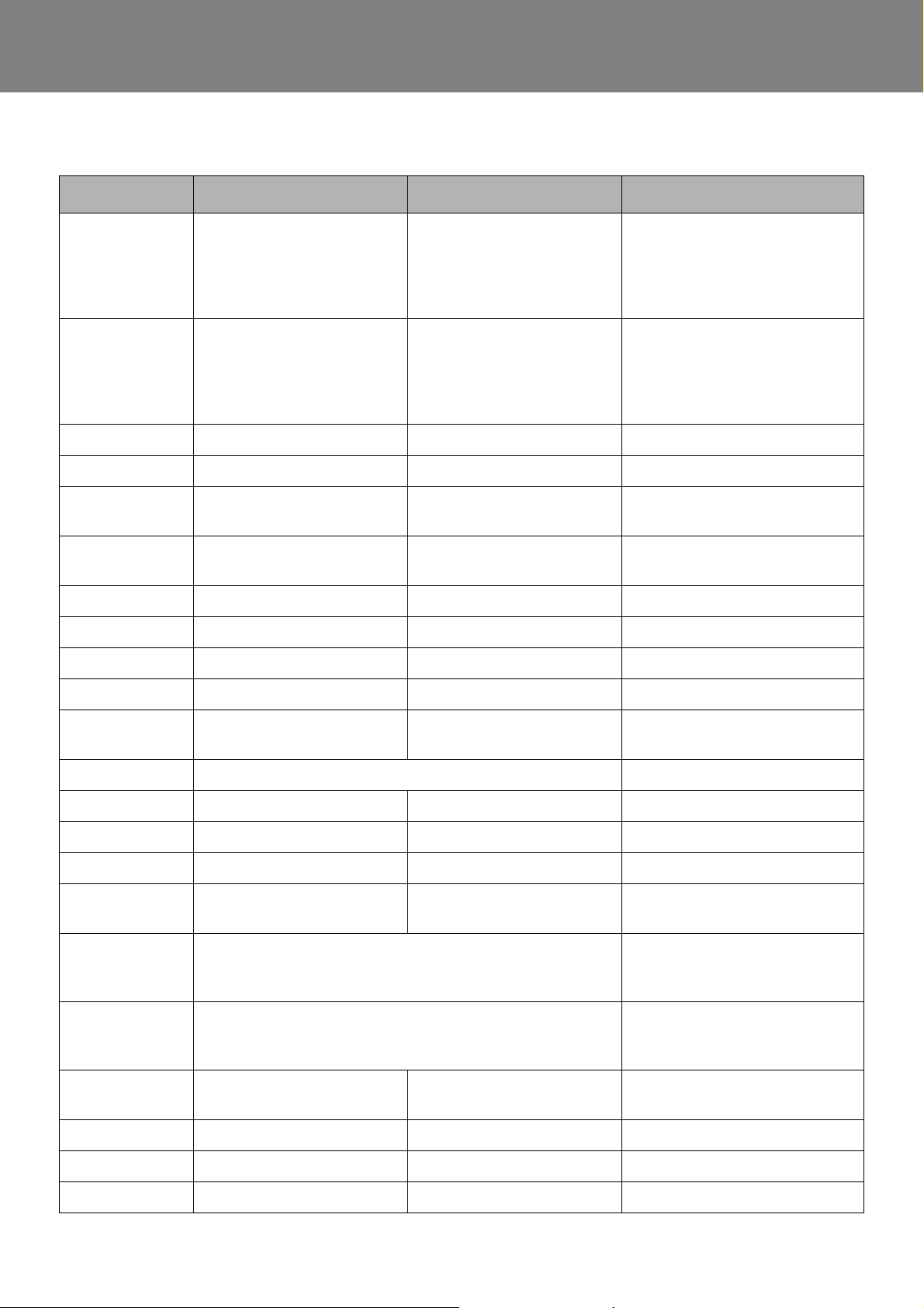
1.8 Abbreviations
Abbreviations DE EN Description
REVO-E HP - ident no. 11120816_
- installed on Volvo E Bus
1st Generation
- lower operating limit
HP ≥ 3°C
REVO-E HP
AC Klimaanlage Air Condition air conditioning only
ADA Aufdachanlage Roof Top Unit
BEA (el.) Body Electrical Architecture electronic regulations of the pas-
DCT Diagnose Control Test Diagnosis Control Test previously Spheros Control Test
EU6 Euro 6 Euro 6 Europe variant
GH Global Hybrid global chassis application
HGA Heißgasabtauung Hot Gas Deicing
HV Hochvolt High Voltage
HVAC Heizen/ Lüften/ Klima Heating/ Ventilation/ Air-
HVIL High Voltage Interlock Loop High voltage interlock loop
+
Conditioning
- ident no. 11123865_
- installed on Volvo E Bus
2nd Generation
- llower operating limit
HP ≥ -5°C
senger compartment
–SCT
i.O. / OK in Ordnung in working order
n.i.O. / NOK nicht in Ordnung not in working order
PE Potentialausgleich Potential Equalizing safety earthing
PTC positiver Temperatur-
koeffizient
SC600 ECU REVO-E AC electronic control unit
SC610 ECU REVO-E AC electronic control unit
SC620 ECU REVO-E WP ECU REVO-E HP electronic control unit
V AC Wechselspannung Volts Alternating Current
V DC Gleichspannung Volts Direct Current
HP Wärmepumpe Heat Pump ADA with heat pump function
Positive Temperature
Coefficient
REVO-E AC (replaced by
SC610)
REVO-E AC (replaced by
SC610)
REVO-E WP
104
Page 9
REVO-E Heat pump 2 Technical specifications
2 Technical specifications
The technical specifications, provided that there are no
limit values given, comply with the standard tolerances for
air-conditioning systems of ±10% for an ambient temperature of +20° C and nominal voltage.
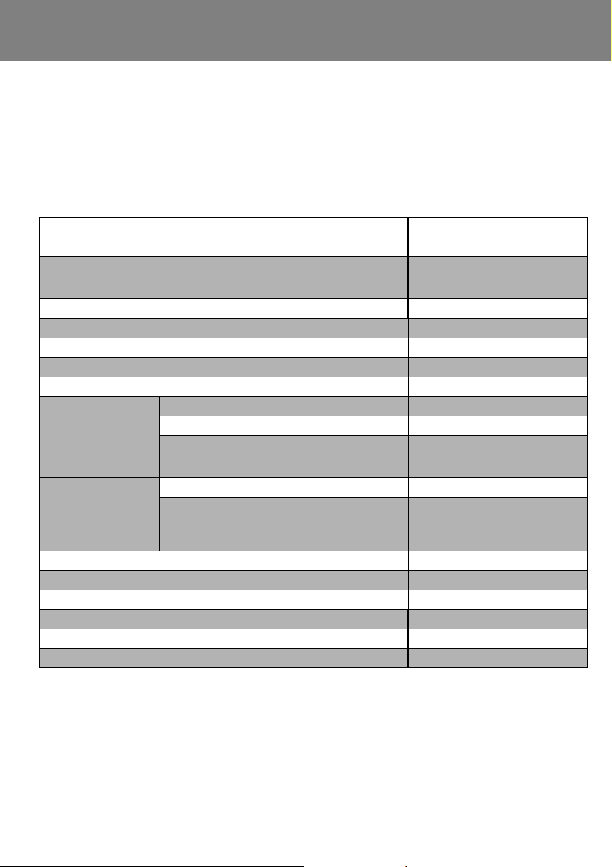
Table 201 Technical specifications
REVO-E heat pump
11123865_
Application Volvo E-Bus 2nd
Generation
(from 2018)
Operating range heat pump [°C] ≥ -5 ≥ 3
Cooling capacity [kW]
Heating capacity in heat-pump-mode [kW]
Heating capacity coolant circuit [kW] 40
Air volume [m³/h] 6960
Current consumption [A]
(24 V DC)
Current consumption [A]
(600 V DC)
1
2
maximum (all 100 %) 85
nominal (condenser 80%, evaporator 70%) 55
regulated
(the temperature in the passenger compartment is at set
point)
maximum (compressor speed at 50Hz) 22
regulated
(the temperature in the passenger compartment is at set
point 25°C - ambient temperature 35 °C, reduced compressor speed)
3
11120816_
Volvo E-Bus 1st
Generation
(till 2018)
25
16
11
9
REVO-E HP+ REVO-E HP
Weight [kg] 272
Dimensions (length x wide x height) [mm] 2802x2091x406
Operation voltage range [V DC] 450-750
Refrigerant R134A
Filling capacity w/o front box[kg] 5
Filling capacity with front box [kg] 5.5
1
) T
2
) T
3
) Version installed two times in articulated vehicle
ambient
ambient
= 35 °C, T
= 5 °C , T
cabin
cabin
= 40 °C
= 20 °C
201
Page 10

REVO-E Heat pump 3 Assemblies and components
REVO-E HP/HP+ (Zone 1)
For connection to front box
REVO-E HP
(11120816_) 1st generation - on solobuses
REVO-E HP+
(11123865_) 2nd generation - on solobuses und
articulated variants
ADA on solobus
REVO-E HP+ (Zone 1)
REVO-E HP
+
(Zone 2)
ADA on articulated system
air conditioning only
11120816_ / 11123865_
11123865_
11123865_
3 Description of assemblies and components
3.1 REVO-E HP versions on the Volvo 79xx Electric
Abb. 1 REVO-E HP Installation variants
301
Page 11
REVO-E Heat pump 3 Assemblies and components
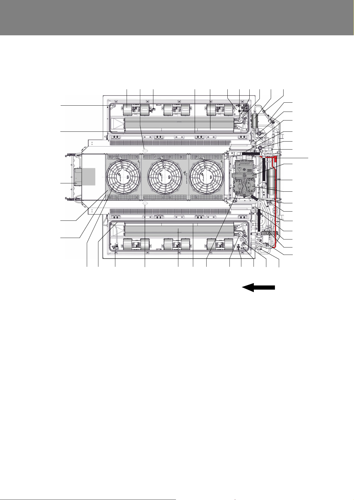
Direction of travel
373839
40
41
42
43
1
14
23
468 97 10
13
5 11
12
15
16
17
18
19
20
21
22
23
24
3435
26
25
27
282930313336
1
) Figure shows 11123865_
2
) Red marked components in 11123865_ only
44
46
45
1 Double radial bl ower
2 Right-hand forward safety lift
point of the unit
3 Blow-out temperature sensor
4 Temperature sensor, passenger
compartment (hidden)
5 Air filter
6 Electrical interface 24V
7 Bleeding port, heating element
NW6
8 Water feed flow NW20
9 Water return NW20
10 Filter Dryer
11 Sight glass
12 Solenoid valve
13 Expansion valve cooling circuit
14 Right-hand rear safety lift point
of the unit
15 Refrigerant charging valve,
suction side
16 Expansion valve heating circuit
heat pump
17 Safety valve, 30bar
18 Bracket, refrigerant compressor
19 Refrigerant collector
20 Refrigerant compressor
21
Refrigerant charging valve,
discharge side
22 Suction pressure sensor
(hidden)
23 Left-hand rear safety lift point of
the unit
24 Expansion valve cooling circuit
25 4-way reversing valve
26 Coil 4-way reversing valve
27 High pressure sensor
28 Refrigerant connection, suction
side, defroster
29 Refrigerant connection, dischar-
ge side, defroster
30 Protective Earth (PE), high
voltage components
31 Bleeding port, heating element
NW6
32 Low pressure safety switch *
33 High pressure safety switch
34 Air filter
35 Inner heat exchanger
36 Left-hand forward safety lift point
of the unit
37 Electrical interface 600V DC
38 Flap actuator (hidden)
39 Axial fan
40 Outer heat exchanger
41 Fan module
42 Frequency inverter
43 Flap actuator (hidden)
44 Solenoid valve hot gas deicing
45 Muffler
46 diagnostics port frequency inver-
ter
* not in 11123865_
3.2 Total overview of the design and components of the REVO-E heat pump
Fig. 2 REVO-E Heat pump total overview
302
Page 12
REVO-E Heat pump 3 Assemblies and components
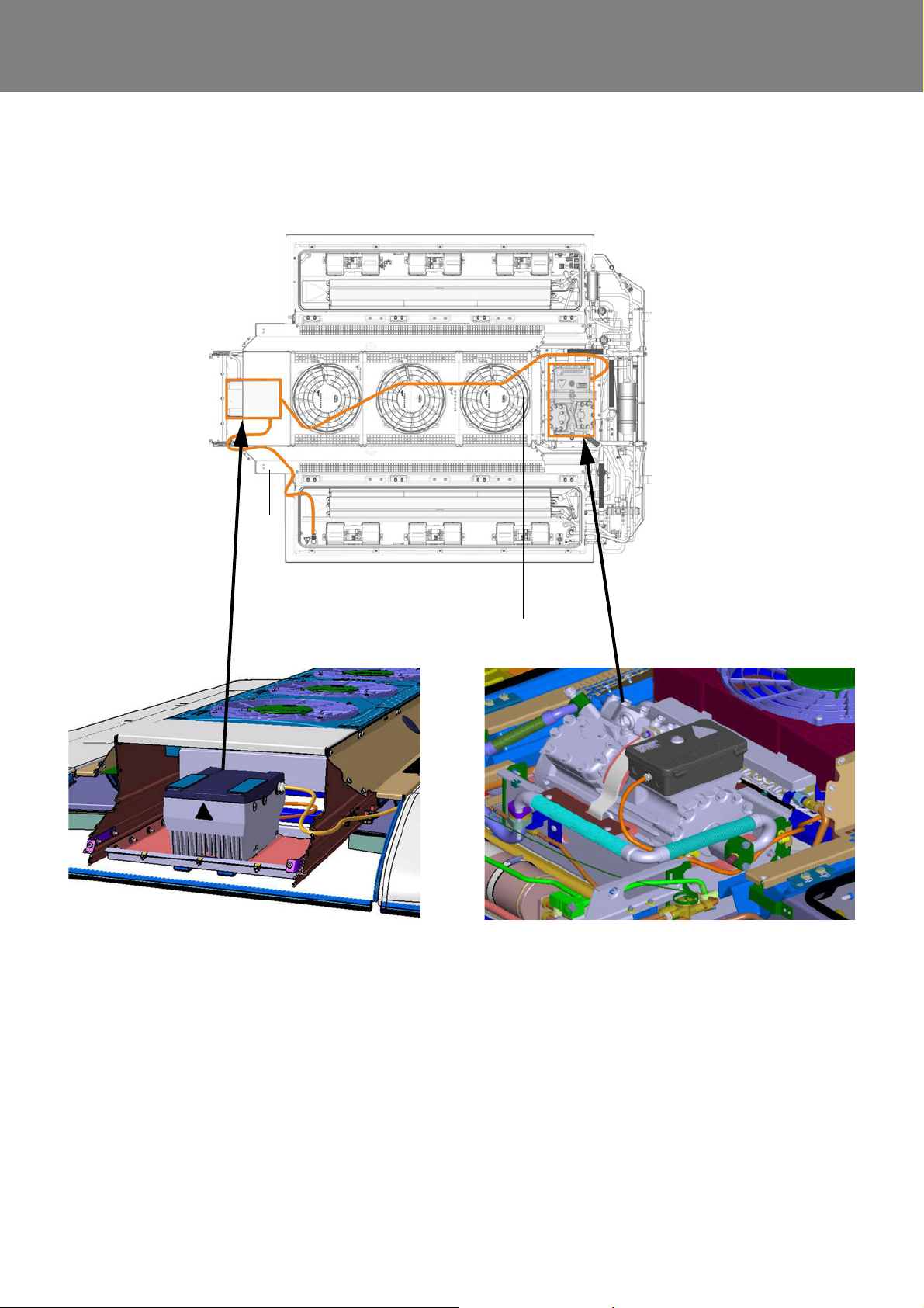
1 - High-voltage power supply of the frequency converter 600V DC
2 - High-voltage power supply of the compressor 3x 400V AC
1
2
Frequency converter
Compressor with 3x 400V AC e-motor
600V DC -> 3x400V AC
3.3 Overview of high-voltage cable harnesses / components (400V AC / 600V DC)
Fig. 3 Overview of high-voltage cable harnesses / components (400V AC / 600V DC)
303
Page 13
REVO-E Heat pump 3 Assemblies and components
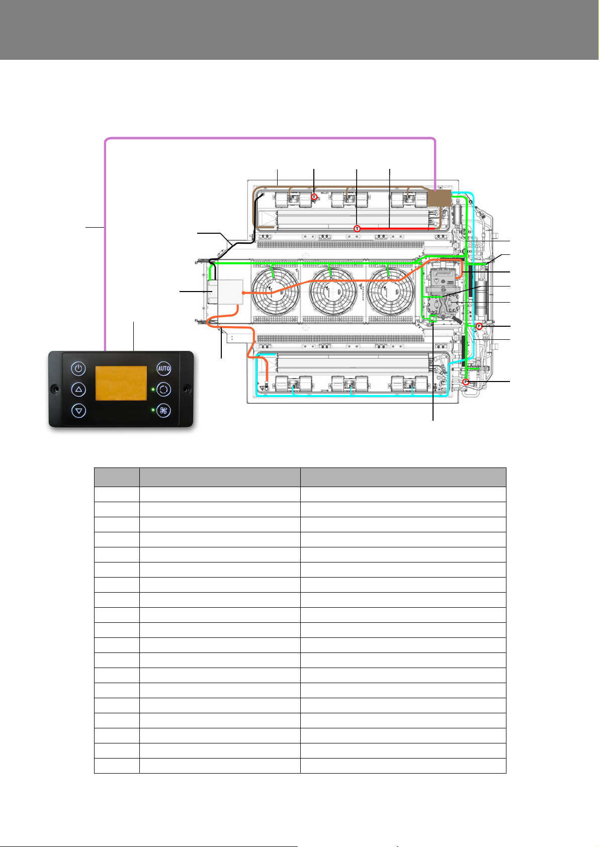
Item Description Remarks
1 wiring harness incl. connection board 24V interface ADA
2 temperature sensor blow out temperature
3 temperature sensor passenger compartment temperature
4 wiring harness temperature sensor passenger compartment
5 wiring harness axial fan, 4-way reversing valve
6 solenoid valve hot gas deicing in 11123865_ only
7 wiring harness kit, 400V AC frequency converter
8 PE connection compressor
9 compressor
10 suction pressure sensor
11 wiring harness double radial fan
12 high pressure sensor
13a high pressure safety switch
13b low pressure safety switch not in 11123865_
14 wiring harness, 600V DC HV interface, vehicle - frequency converter
15 frequency converter 600V DC -> 3x400V AC
16 diagnostic cable frequency converter
17 wiring harness control unit SC620 to ADA
18 SC620 control device installed in Volvo E bus
18
14
4321
5
6
7
17
8
9
10
15
11
12
13a/13b
16
3.4 Cable harnesses overview (high-voltage / low-voltage) in the REVO-E HP
Fig. 4 Cable harnesses overview (high-voltage / low-voltage) in the REVO-E HP
304
Page 14

REVO-E Heat pump 3 Assemblies and components
3.5 Design / task and function of
the assemblies
The REVO-E heat pump features an outer and an inner
heat exchanger.
They consist of aluminum tubes and aluminum fins which
are jointly connected and form a large heat excha ng e r
surface.
Outer heat exchanger
In the air-conditioning mode it works as condenser. If the
unit is in the heat pump mode, it is working as evaporator.
Inner heat exchanger
In the air-conditioning mode they work as evaporator. If
the unit is in the heat pump mode, they are working as
condenser.
Condenser function
It cools the hot refrigerant gas in such a way that it liquefies, subcools and transfers the condensation heat to the
external air flowing through it via the fins.
Evaporator function
The evaporator absorbs the heat from its environ ment and
delivers it to the refrigerant. In this process the evaporation temperature must be lower than the ambient temperature.
By the simultaneous suction action of the refrigerant
compressor and the constriction of the expansion
member, the desired evaporation temperature can be
achieved in a targeted manner.
The heat flowing because of the temperature difference
between the evaporator and the environment causes the
refrigerant liquid fed in by the expansion element to evaporate (evaporation zone) and to overh eat (o ve rh ea tin g
zone) in the evaporator.
balances out changes in the refrigerant circ uit .
Dryer
The interior of the dryer cont ains a granulate that removes
small amounts of water from the refrigerant and chemically binds to it.
The dryer also filters contaminates from the refrigerant
that might lead to malfunctions.
A further expansion valve for heat pump operation is
installed in the heat pump.
Thermostatic expansion valve
The thermostatic expansion valve with external pressure
equalization regulates the refrigerant flow to the
compressor, depending on the refrigerant needs or the
condenser temperature. The thermostatic expansion
valve is the control element between the high and low
pressure sections of the refrigerant circuit.
Pressure switch
The high and low pressure switches are installed on the
compressor and are a key component of the safe ty chain
of the air-conditioning system.
High pressure switch
– Monitors the pressure level in the high-pressure area
of the refrigerant circuit
– Deactivates the air-conditioning system if pressure is
too high (e.g. too much refrigerant)
Low pressure switch
– Monitors the pressure level in the low-pressure area
of the refrigerant circuit
– Deactivates the air-conditioning system if pressure is
too low (e.g. too little refrigerant)
– T he low pressure switch is not installed in the
11123865_ and is replaced by an SW algorithm.
Compressor (HGX34P/315-2 A)
This semi-hermetic, 4 cyl. reciprocating compressor is
driven by a 2 pole, asynchronous motor integrated into the
housing. It is flushed / cooled by R134a, a gaseous r efrigerant, and an integrated PTC element monitors the
temperature level. Signals are evaluated by the frequency
converter . The frequency converter also provides power
and controls the speed.
The duty of the compressor is to condense vaporous
refrigerant from low pressure to a higher pressure. To do
so, it must ensure the necessary discharge (refrigerant
flow) required for cooling.
The compressor is integrated into the air-conditioning
system. The compressor with patented vibration decoupling design is created using a special absorption foam.
The compressor is embedded and fixed in this foam.
Receiver
The receiver is a compensating/ storage tank which
Switch point
Switch point High pressure
switch
On 19 ± 1.5 bar
(relative)
Off 24 ± 1.0 bar
(relative)
1
) not in 11123865_
Low pressure
switch
1.8 ± 0.3 bar
(relative)
0.3 ± 0.3 bar
(relative)
1
Axial fans
The three axial fans are driven by EC motors.
If Cooling Mode is activated, the fans are continuously
controlled depending on the load (refrigerant pressure)
via the PWM, and provide the outer heat exchanger with
sufficient fresh air.
305
Page 15

REVO-E Heat pump 3 Assemblies and components
Double radial blowers
The six double radial blowers are driven by EC motors.
The blowers move recirculated / fresh air through the heat
inner exchanger and blow it at the right temperature
(depending on the mode) into the air ducts of the vehicle.
Speed controls are continuous (PWM); e.g. speed is
reduced when the desired passenger compartment
temperature has been reached. This reduces energy
needs and helps to stabilize the passenger cabin temperature.
Frequency converter
This component is supplied via the 600V DC electrical
system of the vehicle and provides 400V AC for the threephase AC motor of the compressor. Depending on system
requirements, the compressor speed is set between
10Hz-50Hz.
The frequency converter is placed onto an adapter plate
(Fig. 803), which makes it easy to remove / install.
4-Way reversing valve
Depending on the position, the 4-way reversing valve activates the air conditioning mode or the heat pump mode.
In zero position, the air conditioning mode is active.
High pressure
The high pressure sensor determines the pressure level in
the permanent high-pressur e ar ea .
In heat pump mode, the target pressur e is approx. 12 bar
depending on the ambient temperature.
Passenger compartment temperature
This sensor measures the air temperature of the
passenger cabin around the intake area of the recirculating air (Fig. 908).
Air duct temperature (blow-out temperatur e)
This sensor measures the air intake temperature of the
air-conditioning system at the first double radial blower,
front right (Fig. 908).
Monitoring the temperature of the e-motor of the
compressor
A PTC element monitors the temperature of the
compressor e-motor. The frequency converter evaluates
the signal without directly influencing the air-conditioning
control.
R25 ≤ 300 Ω
If the e-motor overheats, the frequency converter stops
the compressor immediately (safety func tio n).
Solenoid valve hot gas deicing REVO-E HP +
The hot gas deicing solenoid valve is installed on the
11123865_ ONLY. It is activated to defrost the outer heat
exchanger with hot gas from the refrigerant circuit.
Sensors
Suction pressure
The suction pressure sensor determines the pressure
level in the permanent low-pressure area. The system
attempts to manage the suction pressure between 3.0 bar
and 3.7 bar (absolute).
Central parameters for:
– climate/ heat pump control
– recognizing icing
– recognizing low pressure
Air valves
Regulate the intake of fresh air or use of recirculated air
from the passenger cabin. The BEA body sends the positional signals “open / closed” via CAN to the SC620 in all
operating modes (except for Gas Charging mode). If both
signals are active, the valves will move to the Recirculating position. Intermediate positions (air mixing) are not
provided in this vehicle.
SC620
This control unit is used as the control device in the Volvo
7900 Electro system (display / keyboard inactive).
HVAC demands are only managed by the BEA body, the
SC620 works as a “slave system” and controls the functions of the ADA.
Two LEDs become active when the system is turned on
(permanent & blinking).
306
Page 16

REVO-E Heat pump 4 Function and functional schematics
4 Function and functional
schematics of the REVO-E Heat pump
4.1 General function
The fully electric rooftop air-conditioning system (in the
following referred to as ADA) REVO-E for hybrid, electric
and trolley buses is a proven system, especially with its
intelligent energy management, meaning cooling is
provided as needed depending on existing power, and
with the special way its compressor has been installed.
The electric compressor is located on the roof in an
exceptionally compact manner, and not on the rear of the
vehicle as in previous versions. This has, in the purest
sense of the word, obvious advantages and makes the
system closed by integrating all of the components
carrying refrigerant, an efficient, tight and almost maintenance free design (solo design without front box connection).
The REVO-E as heat pump
The REVO-E air-conditioning system is the basis for the
REVO-E heat pump.
The refrigeration cycle of the REVO-E air-conditioning
system has been modified in such a way that it can also
represent the functionality of a heat pump in addition to
the air-conditioning operation. The basic principle is
based on the reversal of the refrigeration cycle.
Regulation and control in the air-conditioning mode correspond to the REVO-E air-conditioning system. Details can
be found in the Workshop Manual REVO-E.
Explanations in the following chapters refer largely to the
new functions of the heat pump.
The intelligent controller logic of the SC620 controls
further the entire system. It communicates with the vehicle
via CAN bus.
The climate control works identical as in the REVO-E
air-conditioning system (see Workshop Manual REVO-E).
The two variants of the REVO-E HP are listed in the Table
201.
Both systems differ only slightly. With the additional function "hot gas de-icing", the REVO-E HP + is able to heat
the passenger compartment in heat pump mode at significantly lower temperatures (≥ -5 ° C). This is realized with
adapted software and additional components in the refri geration cycle.
Functionality of the REVO-E Heat pump in the vehicle
line of the Volvo 7900 Electric
The HVAC control system of the vehicle is responsible for
regulating the Heating, Ventilation and Cooling modes in
the Volvo E Bus. The REVO-E system is operated only as
a “slave” system and only follows the vehicles requir ements.
If the ADA is activated by switching on the vehicles electrical network. all of the system’s sensor values are au tomatically verified for plausibility and the system will be set
to “Standby Mode”. Various sensor values are used as the
basis for calculating the bus-side requirements, including
those from the passenger cabin sensors of the ADA.
These requirements are sent via CAN bus over the Dbus
to the SC620 as needed.
The SC620 implements these requirements (mode /
blower speed, etc.).
The REVO-E will turn off if there are any limitations in the
temperature / high-voltage supply, etc.
401
Page 17
REVO-E Heat pump 4 Function and functional schematics
Analog input
HVIL 1 voltage
Analog input
HVIL 2 voltage
CAN interface
vehicle
SC620
Sensor
blow-out
temperature
Sensor
pass. comp.
temperature
Double radial blower
Speed
Compressor
Fresh air
flaps actuator
Double radial blower
Axial fans
Frequency
converter
Fresh air
flaps
actuator
active
Compressor activate
4
5
1
2
3
6
7
NOTE:
Details about the positions can be found in
the overview Fig. 2 in Chapter 3 of the
workshop manual.
1 Solenoid valve
2 Solenoid valve HGA / actu-
ator (in 11123865_only)
3 Suction pressure sensor
4 High pressure safety switch
5 Low pressure safety switch
(not in 11123865_)
6 4-way reversing valve
7 High pressure sensor
24V
4-way reversing valve works as actuator
4.2 Functional schematic of the REVO-E heat pump
Tasks of the SC620
– Implementing climatic and heat pump requirements
– Turning off high-voltage components in case of error
(HVIL)
– Component protection of the climate unit if overloaded
Required to start the system:
– Power supply clamp 30 (main switch of battery)
– Ignition on (clamp 15)
– CAN communication between vehicle and SC620 ac-
tivated - approval for system start shared
– High voltage to the frequency converter, that means
high voltage system active
– Approval (D_AuxiliaryPowerEnable) and supply
Fig. 401 Functional schematic of the REVO-E
402
Page 18
REVO-E Heat pump 4 Function and functional schematics
Analog input
HVIL 1 voltage
Analog input
HVIL 2 voltage
CAN interface
vehicle
SC620
Sensor
blow-out
temperature
Sensor
pass. comp.
temperature
Double radial blower
Speed
Compressor
Fresh air
flaps actuator
Double radial blower
Axial fans
Frequency
converter
Fresh air
flaps
actuator
active
Compressor activate
4
5
1
2
3
6
7
1 Solenoid valve
2 Solenoid valve HGA / actu-
ator (in 11123865_only)
3 Suction pressure sensor
4 High pressure safety switch
5 Low pressure safety switch
(not in 11123865_)
6 4-way reversing valve
7 High pressure sensor
24V
D-Bus Volvo
4-way reversing valve works as actuator
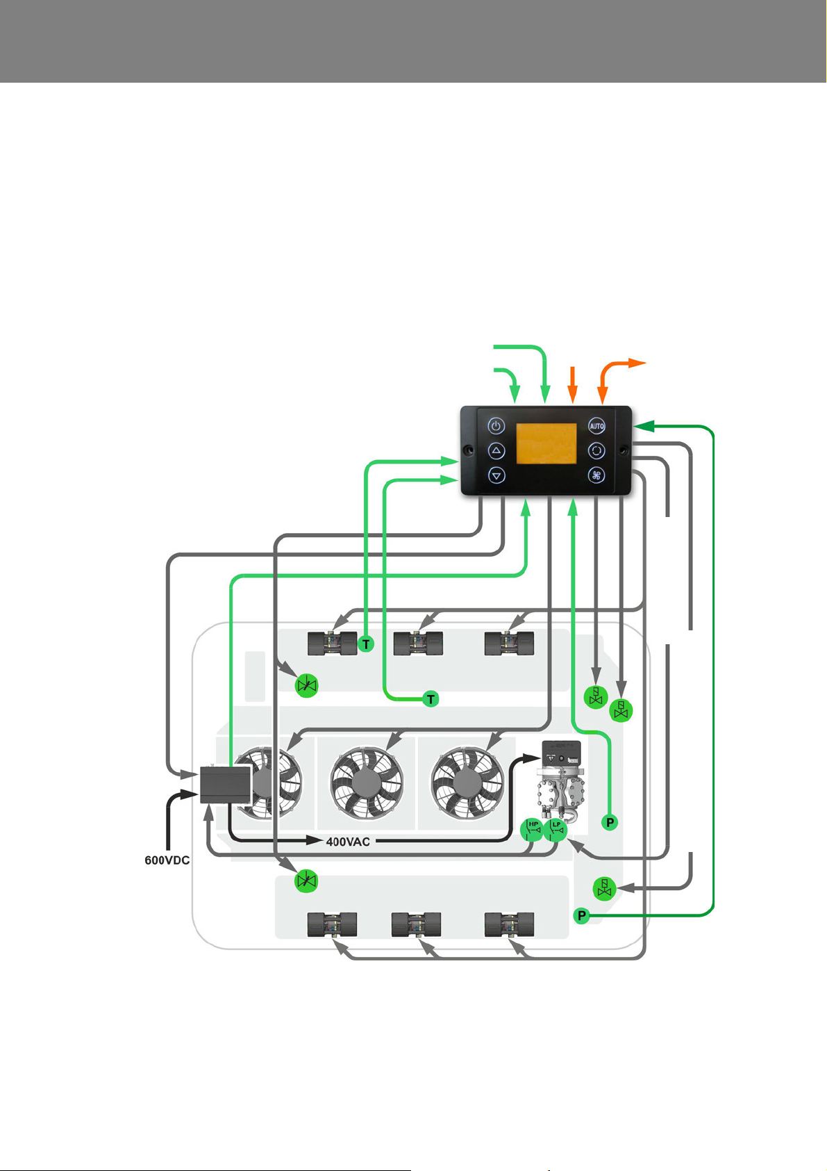
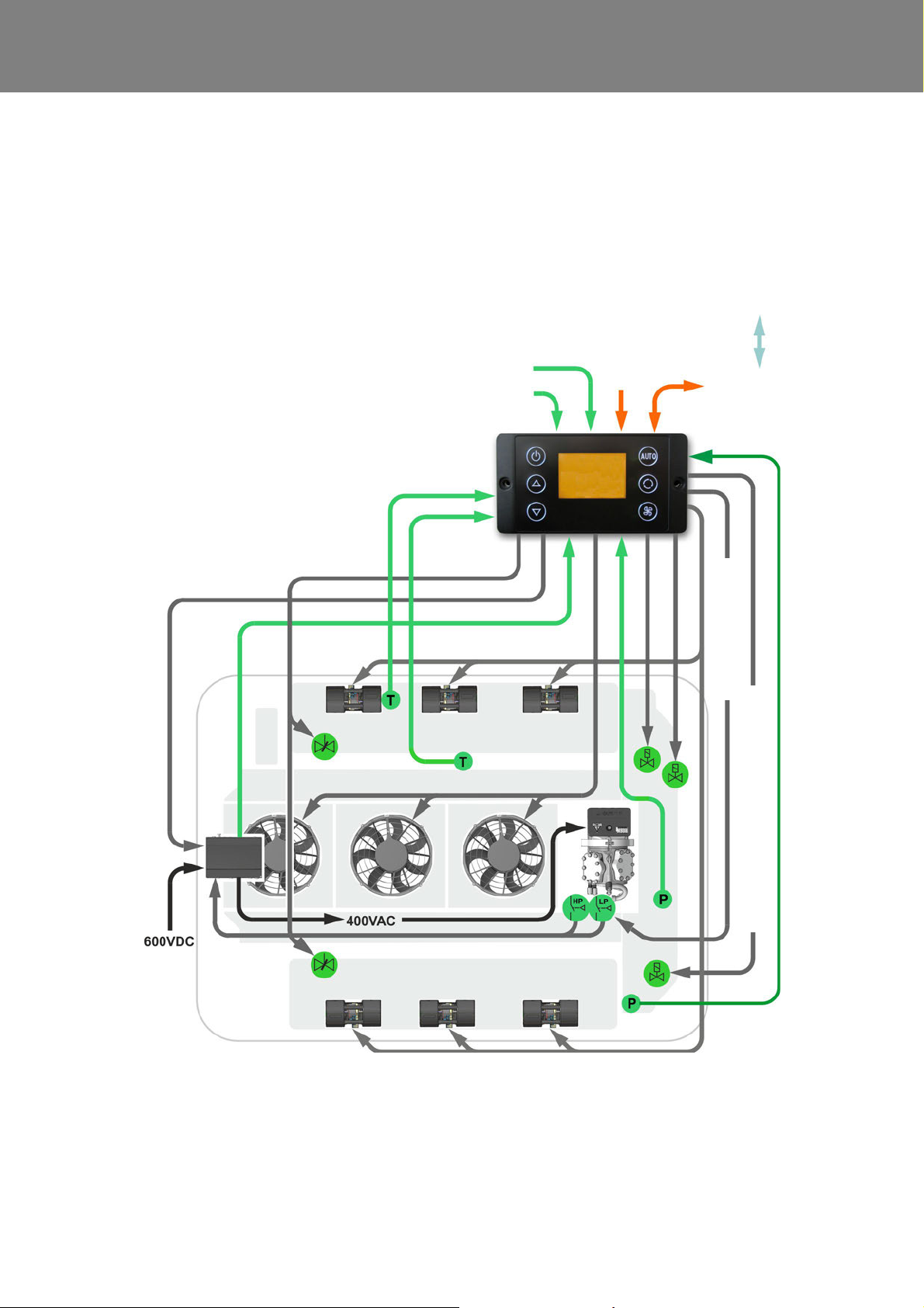
4.3 Functional schematic of the REVO-E heat pump Volvo 7900 Electric
On single buses, the ADA and SC620 are connected to
one another using a Valeo cable harness.
The HVAC control system of the BEA body system is responsible for regulating the Heating, Ventilation, Cooling
and Heat pump modes in the Volvo e-bus.
The REVO-E system therefore behaves only as a “slave”
system and implements the particular requirements.
In Heating / Ventilation or Reheat Mode, the vehicle
controller gives the speed of the double radial blowers.
In Cooling, Waste Energy or Gas Charging Mode, the
double radial blowers are controlled by the SC620.
.
Fig. 402 Functional schematic of the REVO-E, internal
403
Page 19

REVO-E Heat pump 4 Function and functional schematics
4.4 Work modes of the REVO-E heat
pump in the Volvo 7900 Electric
There are 9 different operating modes.
The well-known 6 operating modes of the REVO-E airconditioning system (see WM REVO-E) are extend ed by
three working modes.
In the following explanations, only the new working modes
are considered.
Choosing or switching between modes occurs according
to defined criteria of the BEA body climate control system.
1. Heating/ Ventilation Mode
2. Heating/ Ventilation Mode Ready for Cooling
3. Heating/ Ventilation Mode Ready for Heat Pump *
4. Cooling Mode
5. Heat Pump Mode *
6. De-Icing Mode ** (11123865_only)
7. Reheat Mode
8. Waste Energy Mode
9. Gas Charging Mode
*) new mode for heat pump
**) in 11123865_only
This is a list of priorities in case several modes are simultaneously required by the BEA body system. The SC620
must employ the mode with the highest priority.
Operating mode De-Icing (in 11123865_ only)
This mode is activated by the SC620 depending on the
state of icing. The BEA body control is only informed
about the mode. In this mode, the heat pump function is
disabled.
General operating mode conditions:
- mode required by BEA body (e.g. Cooling Mode to
reduce the temperature in passenger compartment or
Heat Pump Mode to increase the temperature in
passenger compartment)
- general system conditions (e.g. external temperatures
/ status of 600V DC system)
- operating mode de-icing not activated
Depending on the mode, the SC620 or BEA body system
will control the actuators.
404
Page 20

REVO-E Heat pump 4 Function and functional schematics
Double radial blower
Double radial blower
Fresh air
flaps
Sensor
pass. comp.
temperature
Sensor
blow-out
temperature
I/O-A module
Vehicle
Requirement
open / close
Heating valve
actuator
Fresh air
flaps
actuator
Analog input
HVIL 1 voltage
Analog input
HVIL 2 voltage
CAN interface
vehicle
SC620
4
5
1
2
3
6
7
24V
for hot water
heat exchanger
ADA
1 Solenoid valve
2 Solenoid valve HGA / actu-
ator (in 11123865_only)
3 Suction pressure sensor
4 High pressure safety switch
5 Low pressure safety switch
(not in 11123865_)
6 4-way reversing valve
7 High pressure sensor
4.4.1 Heating and Ventilation Mode (HV Mode)
Requirements:
– Clamp 30 active
– HV Mode required by BEA body
Both modes are required directly by the BEA body.
CAN messages from the BEA body to SC620 for defined
speed of double radial blowers and position of air flaps
(fresh air / recirculating air).
Water valves are controlled by the BEA body directly.
Fig. 403 Heating and Ventilation Mode (HV Mode)
405
Page 21
REVO-E Heat pump 4 Function and functional schematics
Double radial blower
Double radial blower
Fresh air
flaps
Sensor
pass. comp.
temperature
Sensor
blow-out
temperature
I/O-A module
Vehicle
Requirement
open / close
Heating valve
actuator
Fresh air
flaps
actuator
Analog input
HVIL 1 voltage
Analog input
HVIL 2 voltage
CAN interface
vehicle
SC620
4
5
1
2
3
6
7
24V
for hot water
heat exchanger
ADA
1 Solenoid valve
2 Solenoid valve HGA / actu-
ator (in 11123865_only)
3 Suction pressure sensor
4 High pressure safety switch
5 Low pressure safety switch
(not in 11123865_)
6 4-way reversing valve
7 High pressure sensor
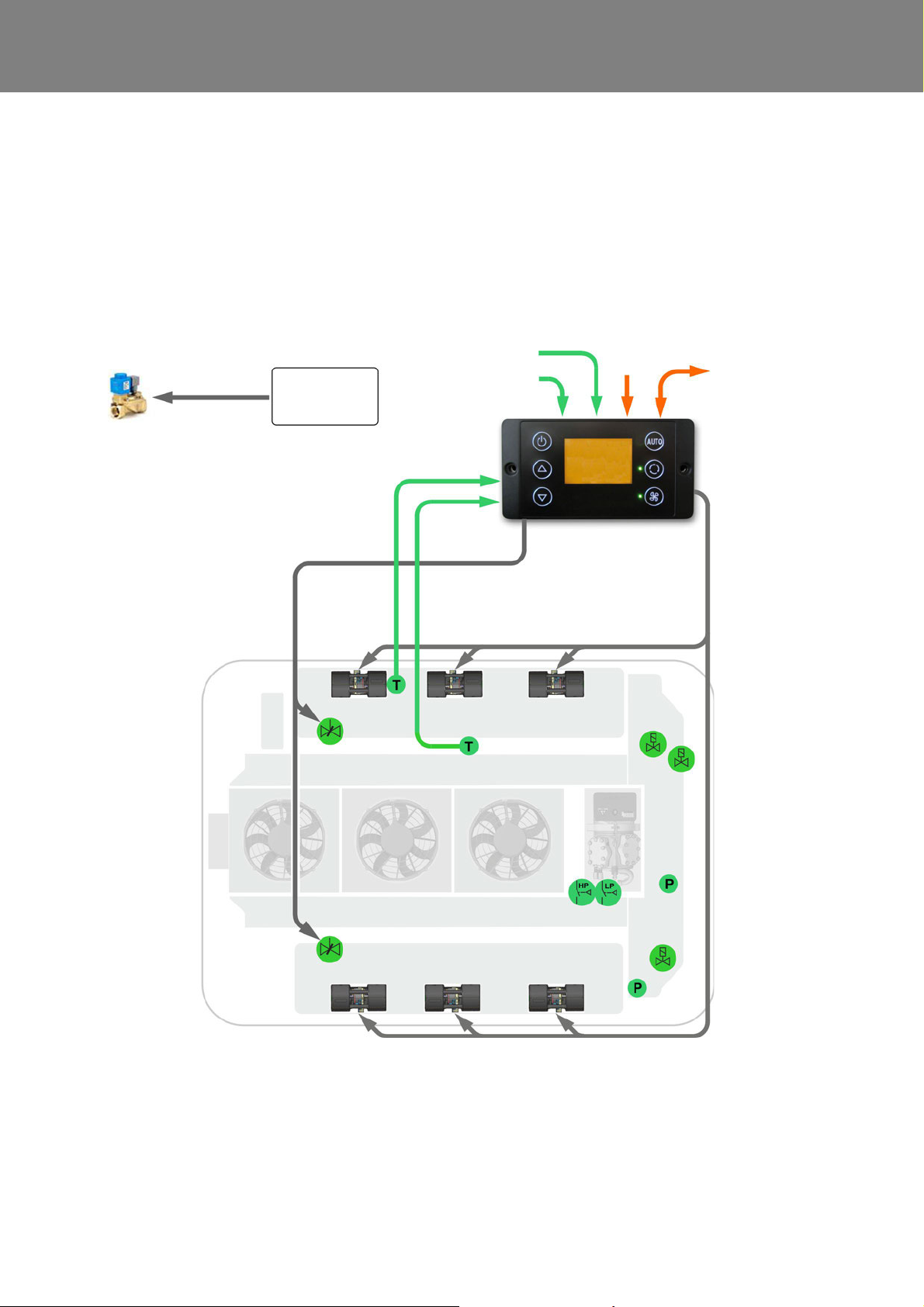
4.4.2 Heating and Ventilation Mode Ready for
cooling
Requirements:
– Clam p 30 / 15 act ive
– Vehicle hybrid system active
– HV Mode required by BEA body
Preconditions for Cooling Mode filled shortly before or
after this, however cool request not sent by BEA body.
System works primarily in Heating / Ventilation Mode.
Fig. 404 Heating and Ventilation Mode Ready for Cooling
406
Page 22
REVO-E Heat pump 4 Function and functional schematics
Double radial blower
Double radial blower
Fresh air
flaps
Sensor
pass. comp.
temperature
Sensor
blow-out
temperature
I/O-A module
Vehicle
Requirement
open / close
Heating valve
actuator
Fresh air
flaps
actuator
Analog input
HVIL 1 voltage
Analog input
HVIL 2 voltage
CAN interface
vehicle
SC620
4
5
1
2
3
6
7
24V
for hot water
heat exchanger
ADA
1 Solenoid valve
2 Solenoid valve HGA / actu-
ator (in 11123865_only)
3 Suction pressure sensor
4 High pressure safety switch
5 Low pressure safety switch
(not in 11123865_)
6 4-way reversing valve
7 High pressure sensor
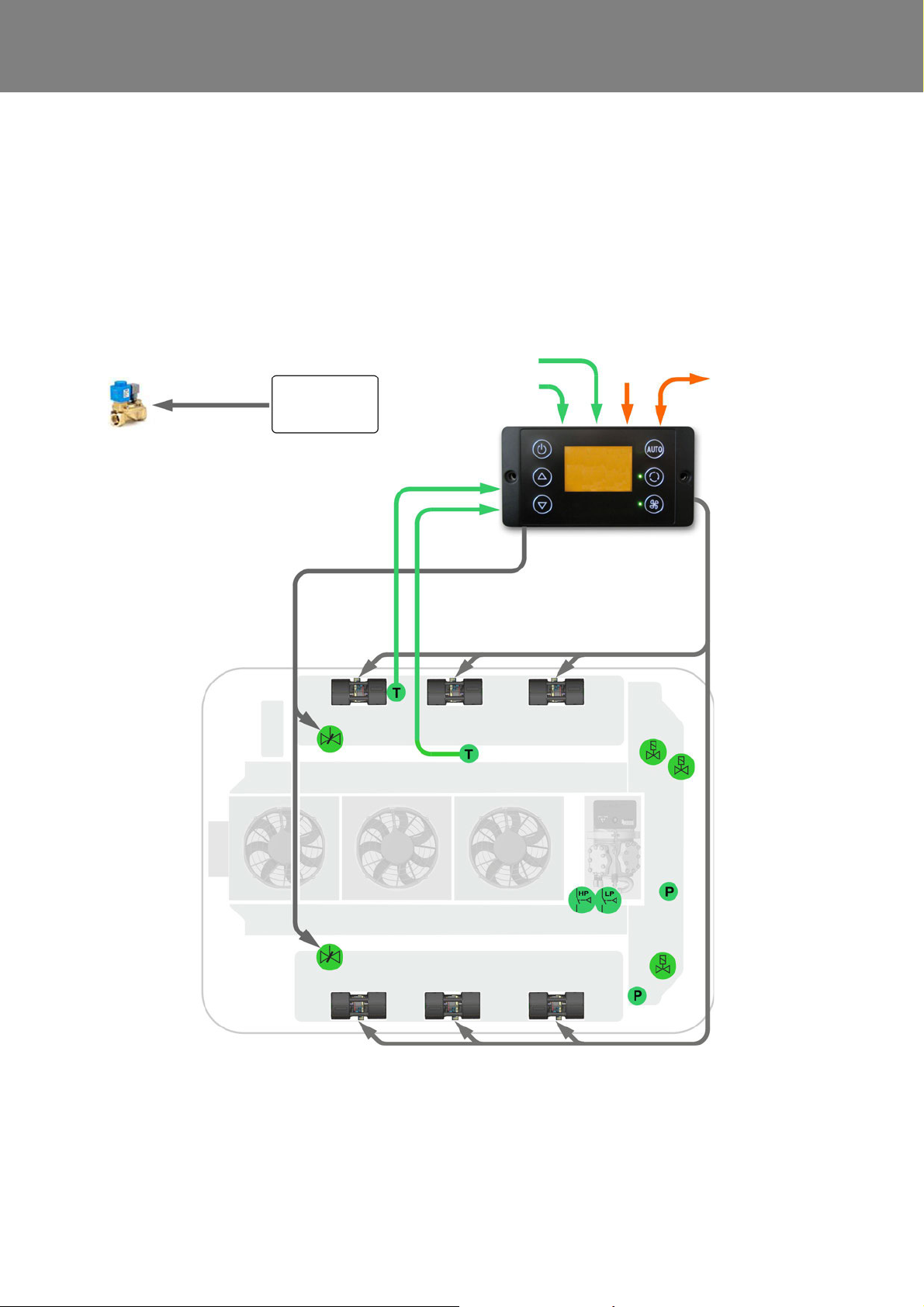
4.4.3 Heating and Ventilation Mode Ready
for Heat Pump Mode
Requirements:
– Clam p 30 / 15 act ive
– Vehicle hybrid system active
– HV Mode required by BEA body
Preconditions for Heat Pump Mode filled shortly before or
after this, however cool request not sent by BEA body.
System works primarily in Heating / Ventilation Mode.
Fig. 405
Heating and Ventilation Mode Ready for Heat Pump
407
Page 23
REVO-E Heat pump 4 Function and functional schematics
Analog input
HVIL 1 voltage
Analog input
HVIL 2 voltage
CAN interface
vehicle
SC620
Sensor
blow-out
temperature
Sensor
pass. comp.
temperature
Double radial blower
Speed
Compressor
Fresh air
flaps actuator
Double radial blower
Axial fans
Frequency
converter
Fresh air
flaps
actuator
active
Compressor activate
4
5
1
2
3
6
7
1 Solenoid valve
2 Solenoid valve HGA / actu-
ator (in 11123865_only)
3 Suction pressure sensor
4 High pressure safety switch
5 Low pressure safety switch
(not in 11123865_)
6 4-way reversing valve
7 High pressure sensor
24V
4-way reversing valve works as actu at o r
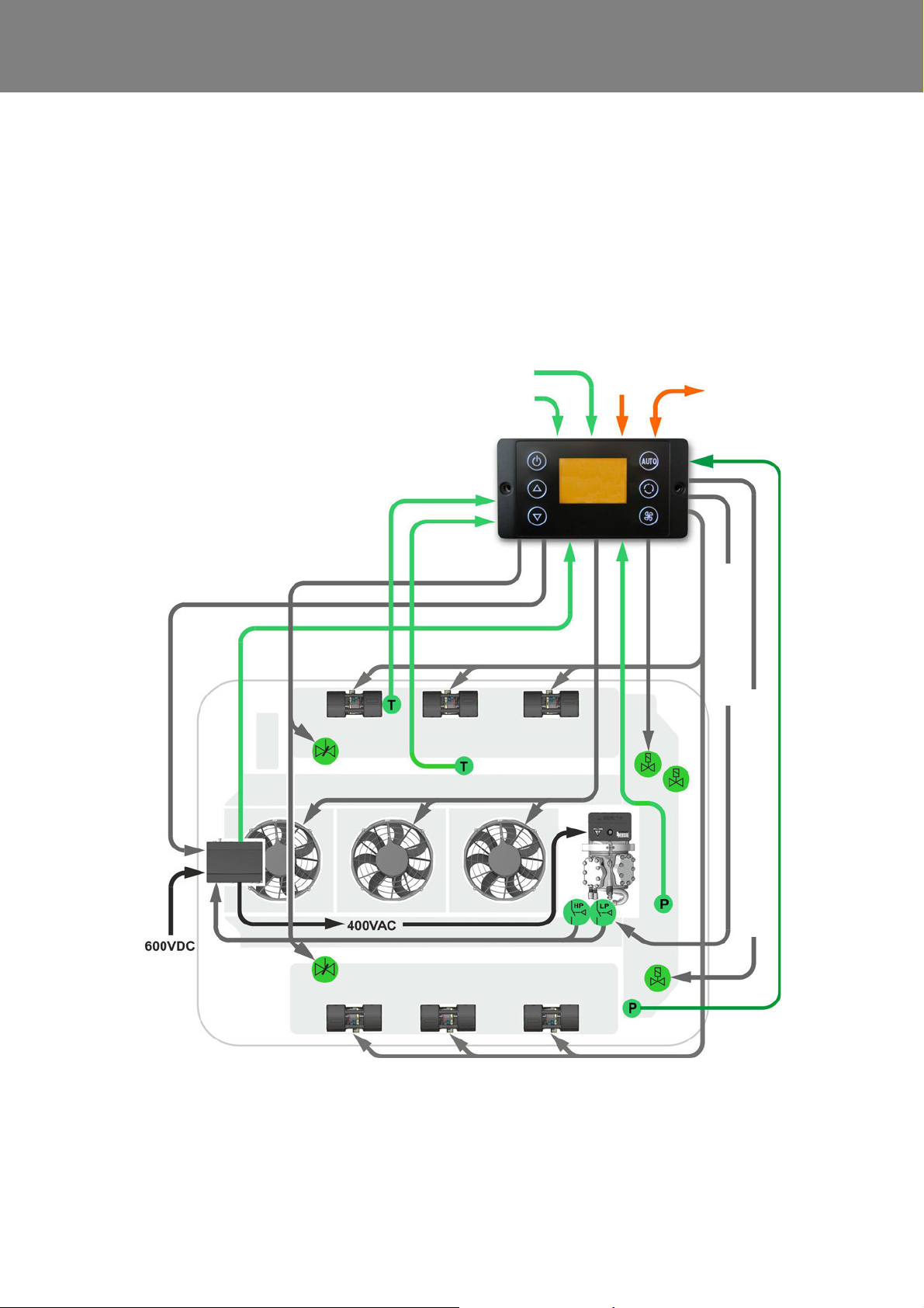
4.4.4 Cooling Mode
Requirements:
– Terminal 15 active
– Vehicle hybrid system active
– Mode “Ready for Cooling“ active
– HVAC power consumption enabled by
“D_AuxiliaryPowerEnabled” signal
– Signal “D_CabinCoolReq” sent by BEA-Body
– environmental temperature > 5°C
The Cooling Mode is requested by the BEA body system
in order to cool down the air in the passenger cabin. The
SC620 therefore assumes internal control of the components in the system in order to cool down the air in the
passenger cabin to the Delta T value requested by the
BEA Body.
Fig. 406 Cooling Mode
408
Page 24

REVO-E Heat pump 4 Function and functional schematics
Task of the SC620:
– Control the speed of the double radial blowers / axial
fans
– Activation and speed setting of the compressor (via
frequency converter)
In Cooling mode Mode, the BEA body is not able to influence the speed of the double radial blowers.
The value of the interior temperature to be reached is
given by the difference of the external temperature and
the ∆T required by the BEA body.
Example of ∆T – 7 Kelvin
T
passenger cabin
T
passenger cabin
= [T
external
= 28°C
(35°C) + ∆T (7K)]
This value is sent via CAN by the BEA body and is used
as an internal control signal.
The "D_ElAcMaxPowerAllowed" CAN signal (from the
vehicle's power system) specifies the maximum power
consumption of the compressor.
If the cooling requested cannot be implemented (e.g.
malfunction), the system automatically switches to
Heating/ Ventilation Mode.
409
Page 25
REVO-E Heat pump 4 Function and functional schematics
Analog input
HVIL 1 voltage
Analog input
HVIL 2 voltage
CAN interface
vehicle
SC620
Sensor
blow-out
temperature
Sensor
pass. comp.
temperature
Double radial blower
Speed
Compressor
Fresh air
flaps actuator
Double radial blower
Axial fans
Frequency
converter
Fresh air
flaps
actuator
active
Compressor activate
4
5
1
2
3
6
7
1 Solenoid valve
2 Solenoid valve HGA / actu-
ator (in 11123865_only)
3 Suction pressure sensor
4 High pressure safety switch
5 Low pressure safety switch
(not in 11123865_)
6 4-way reversing valve
7 High pressure sensor
24V
4-way reversing valve works as actu at o r
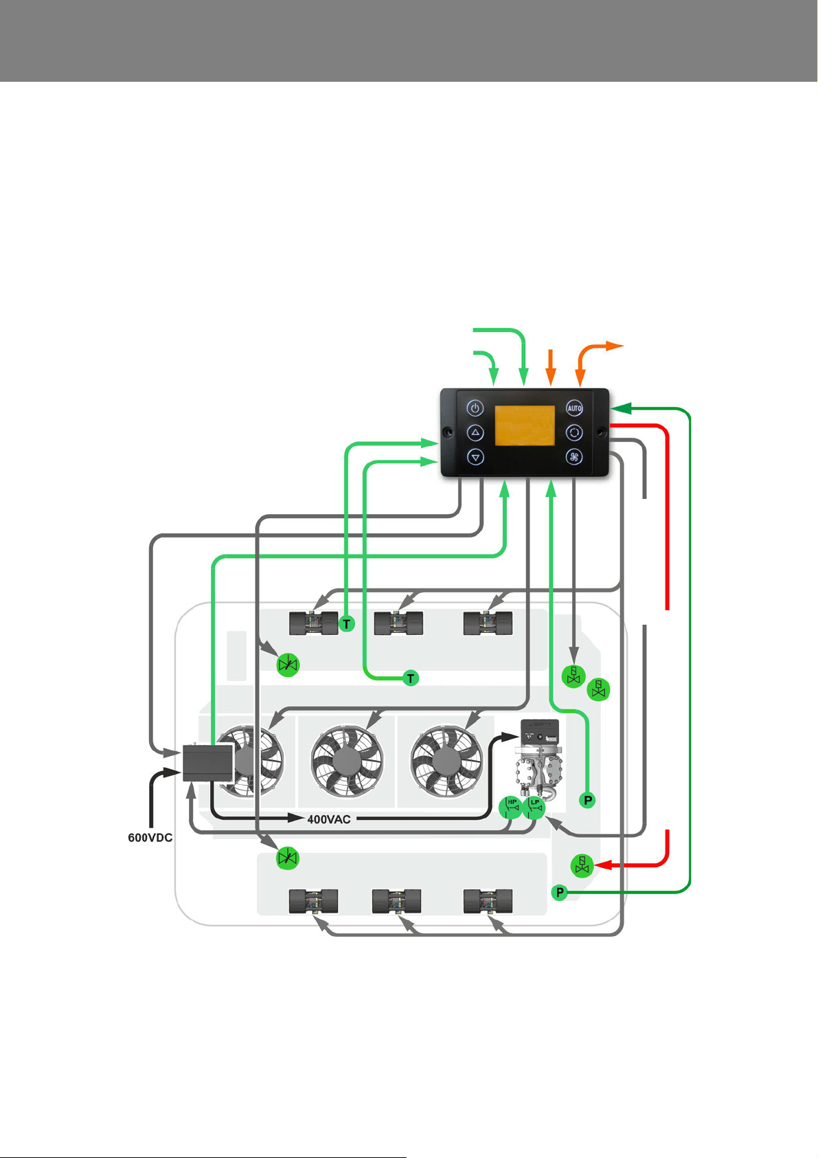
4.4.5 Heat Pump Mode
Requirements:
– Environmental temperature ≥ -5°C (11123865_)
– Environmental temperature ≥ 3°C (11120816_)
– no frequency converter or compressor errors
– no low-voltage error
– Terminal 15 active
– Vehicle hybrid system active
– HVAC power consumption enabled by
“D_AuxiliaryPowerEnabled” signal
– n o HVIL error
– ∆T temperature passenger compartment > 0K
– SC 620 CAN message “heat pump available“ to BEA
body
– “D_CabinHeatpumpReq” signal sent by BEA body
Fig. 407 Heat Pump Mode
410
Page 26

REVO-E Heat pump 4 Function and functional schematics
The Heat Pump Mode is requested by the BEA body
system in order to warm up the air in the passenger cabin.
The SC620 therefore assumes internal control of the
components in the system in order to warm up the air in
the passenger cabin to the Delta T value r equested by the
BEA Body.
In the heat pump mode, the refrigerant circuit to the front
box (driver's work station) is closed by a solenoid valve
controlled of the BEA-Body SW. This prevents a sudden
fogging of the front windscreen (flash fogging).
Task of the SC620:
– Control the speed of the double radial blowers / axial
fans
– Activation and speed setting of the compressor (via
frequency converter)
In Heat Pump Mode, the BEA body is not able to influence
the speed of the double radial blowers.
The value of the interior temperature to be reached is
given by the difference of the external temperature and
the ∆T required by the BEA body.
Example of ∆T – 7 Kelvin
T
passenger cabin
T
passenger cabin
= [T
external
= 17°C
(10°C) + ∆T (7K)]
This value is sent via CAN by the BEA body and is used
as an internal control signal.
The "D_ElAcMaxPowerAllowed" CAN signal (from the
vehicle's power system) specifies the maximum power
consumption of the compressor.
If the heat required cannot be implemented (e.g. ma lfunction), the system automatically switches to Heating/ Ventilation Mode.
411
Page 27
REVO-E Heat pump 4 Function and functional schematics
Analog input
HVIL 1 voltage
Analog input
HVIL 2 voltage
CAN interface
vehicle
SC620
Sensor
blow-out
temperature
Sensor
pass. comp.
temperature
Double radial blower
Speed
Compressor
Fresh air
flaps actuator
Double radial blower
Axial fans
Frequency
converter
Fresh air
flaps
actuator
active
Compressor activate
4
5
1
2
3
6
7
1 Solenoid valve
2 Solenoid valve HGA / actu-
ator (in 11123865_only)
3 Suction pressure sensor
4 High pressure safety switch
5 Low pressure safety switch
(not in 11123865_)
6 4-way reversing valve
7 High pressure sensor
24V
4-way reversing valve works as act u at o r
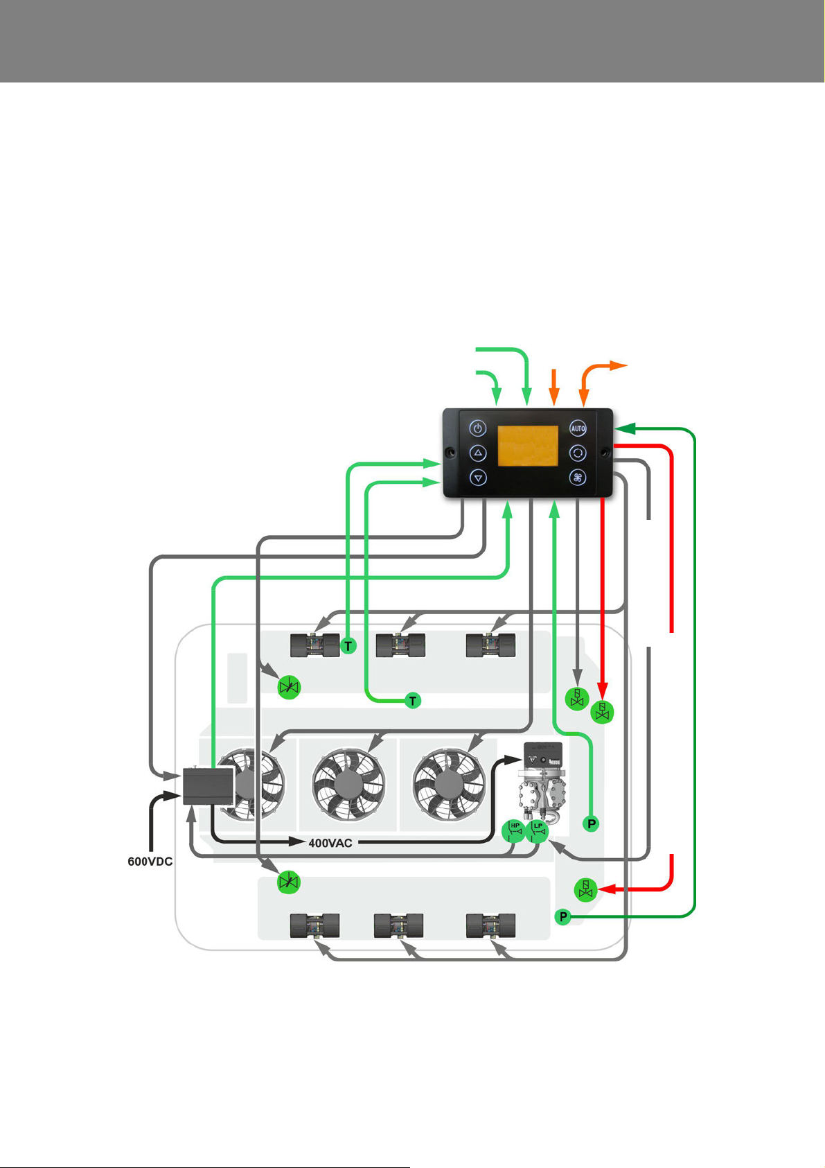
4.4.6 Operating Mode De-Icing)
(Version HP+ only)
Requirements:
– Start of Heat Pump Mode or 1h Heat Pump Mode op-
eration
– Environmental temperature ≥ -5°C (REVO-E HP+)
– no frequency converter or compressor errors
– no low-voltage error
– Terminal 15 active
– Vehicle hybrid system active
– HVAC power consumption enabled by
“D_AuxiliaryPowerEnabled” signal
– n o HVIL error
– ∆T temperature passenger compartment > 0K
– SC 620 CAN message “heat pump available“ to BEA
body
– “D_CabinHeatpumpReq” signal sent by BEA body.
Fig. 408 Operating Mode De-Icing
412
Page 28

REVO-E Heat pump 4 Function and functional schematics
This mode is only available with the REVO-E HP + (additional solenoid valve) and allows the use of the system up
to an outside temperature of -5°C.
For component safety, the SC620 starts the De-Icing
Mode each time before starting the heat pump function.
Furthermore, the de-icing is activated after one hour Heat
Pump Mode and takes between 2 min and 15 min depending on the degree of icing of the outer heat exchanger.
In order to use the necessary energy for the fastest
possible de-icing, the double radial blowers are switched
off during this time.
The BEA body control is informed via CAN from the
SC620 about the mode and heats the passenger compa rtment via the floor heating circuit.
4.4.7 Operating Mode Oil Recovering
(Version HP+ only)
Serves to protect the compressor.
After approx. 4 hours in heat pump mode, the ADA
switches to the oil return mode. The refrigeration oil
distributed in the ADA is thus returned to the compressor.
413
Page 29
REVO-E Heat pump 4 Function and functional schematics
Double radial blower
Double radial blower
Fresh air
flaps
Sensor
pass. comp.
temperature
Sensor
blow-out
temperature
I/O-A module
Vehicle
Requirement
open / close
Heating valve
actuator
Fresh air
flaps
actuator
Analog input
HVIL 1 voltage
Analog input
HVIL 2 voltage
CAN interface
vehicle
SC620
4
5
1
2
3
6
7
24V
for hot water
heat exchanger
ADA
1 Solenoid valve
2 Solenoid valve HGA / actu-
ator (in 11123865_only)
3 Suction pressure sensor
4 High pressure safety switch
5 Low pressure safety switch
(not in 11123865_)
6 4-way reversing valve
7 High pressure sensor
Compressor activate
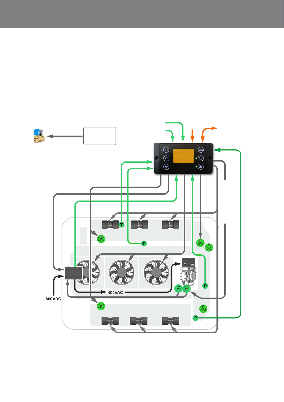
4.4.8 Reheat Mode
Requirements:
– Clamp 15 active (ignition)
– Vehicle hybrid system active
– The HVAC's po we r ne ed s ar e en ab le d by the sig na l
"D_AuxiliaryPowerEnabled"
– “D_CabinReheatReq” signal is requested by the BEA
body
– Environmental temperature >5°C
Reheat Mode is requested by the BEA body (air drying in
passenger compartment).
The SC620 activates the compressor and the axial fans
for maximum cooling.
The BEA body system activates the valves of the roof-top
heater simultaneously. Hot coolant is delivered to the heat
exchangers of the ADA.
The counter-heating in reheat mode is carrie d out via th e
water heat exchangers installed in the system. The heat
pump function can not do this.
The maximum condenser capacity can be limited by the
"D_ElAcMaxPowerAllowed" signal.
Fig. 409 Reheat Mode
414
Page 30
REVO-E Heat pump 4 Function and functional schematics
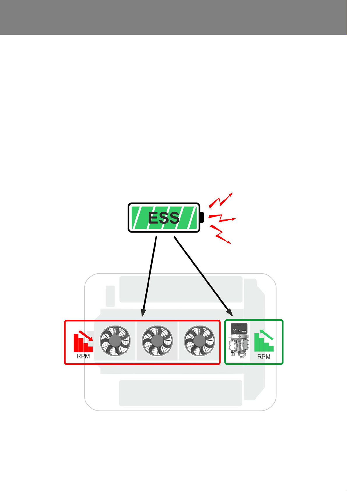
4.4.9 Waste Energy Mode
Requirements:
– Clamp 15 active (ignition)
– Vehicle hybrid system active
– The HVAC's po we r ne ed s ar e en ab le d by the sig na l
"D_AuxiliaryPowerEnabled"
– “D_CabAcWasteEnergyReq” signal is requested by
the BEA body
– Environmental temperature >5°C
This is achieved by running back the efficiency of the airconditioning system, e.g. by reducing the speed of the
axial fans.
The reduction in power must occur without any noticeable
change to the conditions in the passenger cabin . This
mode is only used to support the power management
system.
In Waste Energy Mode, the air-conditioning system
attempts to dissipate additional energy from the drive
battery.
The maximum condenser capacity can in turn be limited
by the "D_ElAcMaxPowerAllowed" signal.
Fig. 410 Waste Energy Mode
415
Page 31
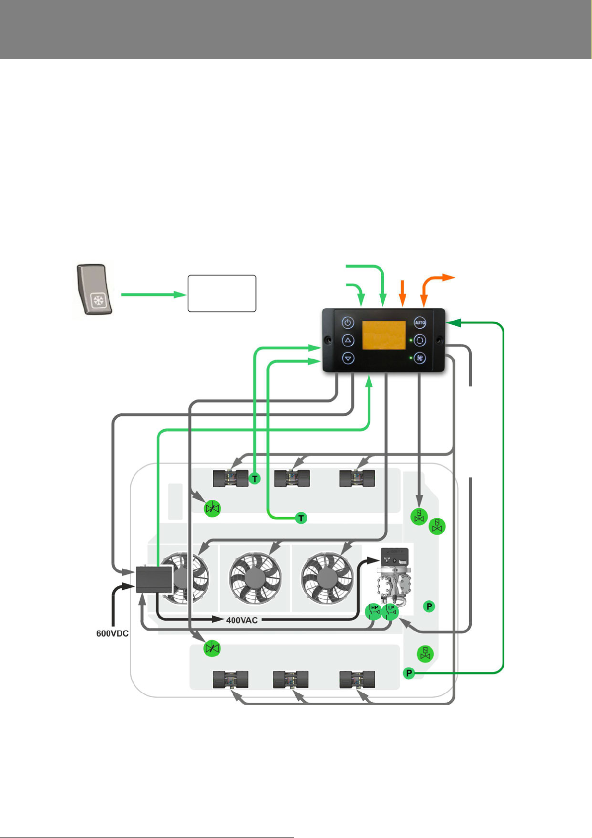
REVO-E Heat pump 4 Function and functional schematics
Double radial blower
Double radial blower
Fresh air
flaps
Sensor
pass. comp.
temperature
Sensor
blow-out
temperature
Request Gas
charging Mode
actuator
Fresh air
flaps
actuator
Analog input
HVIL 1 voltage
Analog input
HVIL 2 voltage
CAN interface
vehicle
SC620
4
5
1
2
3
6
7
24V
1 Solenoid valve
2 Solenoid valve HGA / actu-
ator (in 11123865_only)
3 Suction pressure sensor
4 High pressure safety switch
5 Low pressure safety switch
(not in 11123865_)
6 4-way reversing valve
7 High pressure sensor
Compressor activate
I/O-A module
Vehicle
4.4.10 Gas Charging Mode
Requirements:
– Clamp 15 active (ignition)
– Vehicle hybrid system active
– The HVAC's po we r ne ed s ar e en ab le d by the sig na l
"D_AuxiliaryPowerEnabled"
– “D_CabAcGasCgeReq” signal is requested by the
BEA body
– Environmental temperature >5°C
The task of Gas Charging Mode is to activate the
compressor to fill the system with the refrigerant R 134a.
Gas Charging Mode works independently with a small ∆T
that is sent by the BEA body to the SC620.
This activates the compressor, the double radial blowers /
axial fans of the REVO-E at minimal power.
Monitoring of the suction pressure is deactivated in
Gas Charging Mode, since the system is normally not
filled when this mode is started and the suction pressure sensor would therefore read a false value in the
vacuum of the system. *
The mode is not part of standard operation a nd is only to
be used by trained servicing personnel.
The maximum condenser capacity can be limited by the
"D_ElAcMaxPowerAllowed" signal.
Fig. 411 Gas Charging Mode
416
Page 32
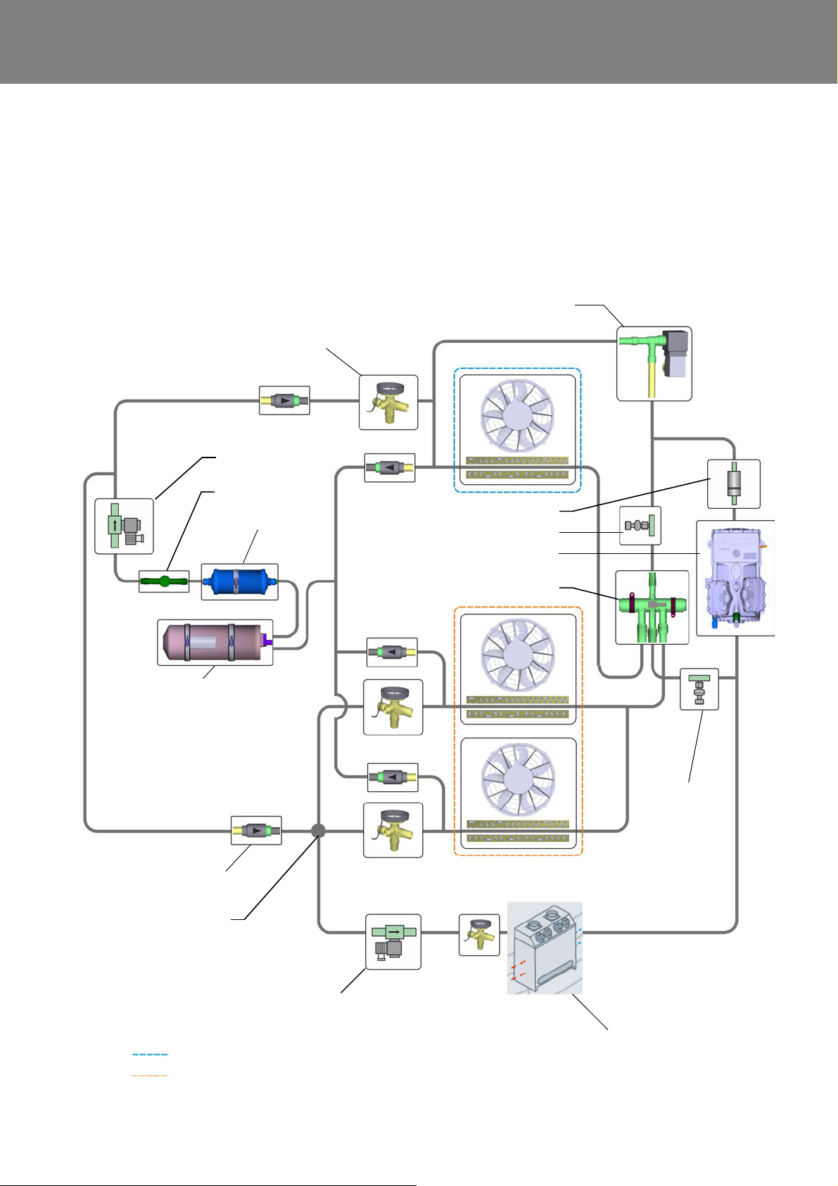
REVO-E Heat pump 4 Function and functional schematics
Outer heat exchanger
Inner heat exchanger (passenger compartment)
Expansion valve
Filter dryer
Receiver
Check valve
4-way reversing valve
Compressor
(ADA 11123865_only)
Muffler
Solenoid valve
Sight glass
3-way distributor
Solenoid valve
Suction
sensor
High pressure sensor
pressure
Solenoid valve hot gas de-icing
Front box
4.5 Refrigerant circuit function schematic of the heat pump
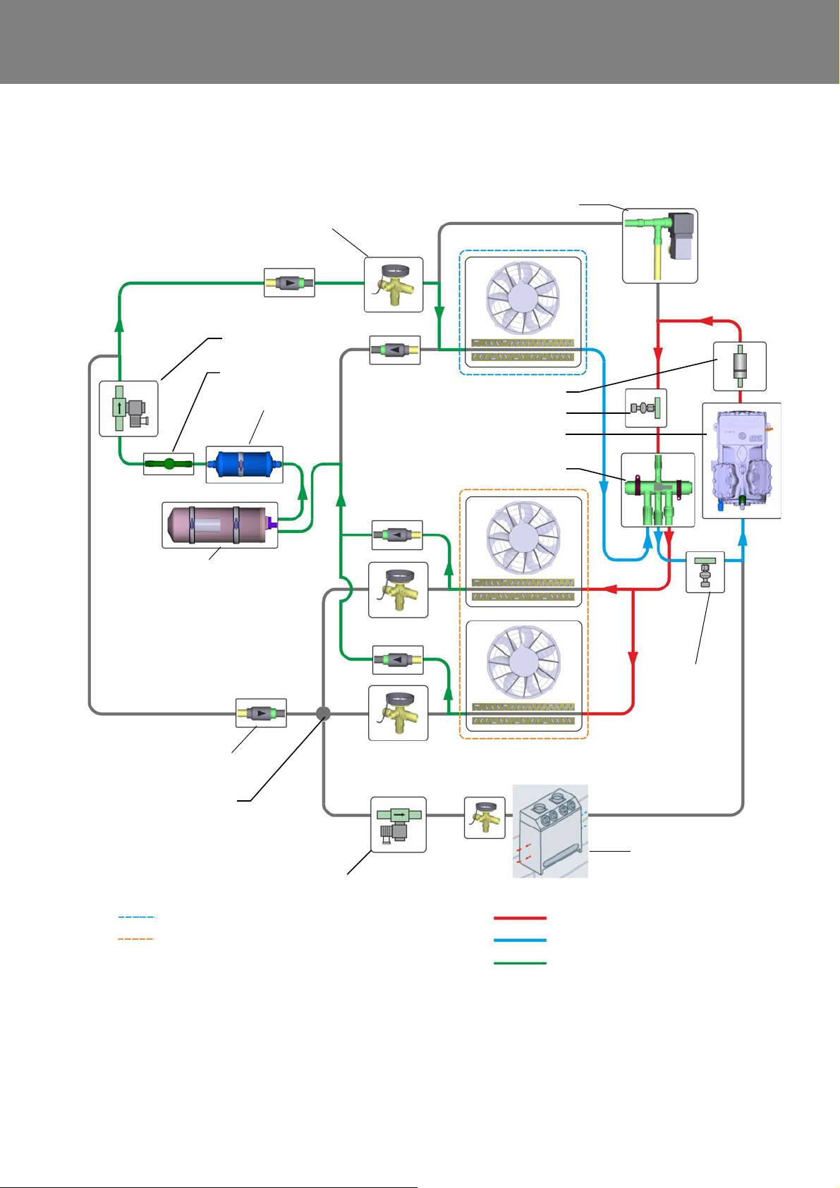
The refrigerant circuit of the REVO-E heat pumps can b e
reversed via a 4-way reversing valve. This changes the
function of the evaporator and the condenser, as they are
known from the REVO-E air conditioning.
Die Verdampfer arbeiten im Wärmepumpen-Modus als
The evaporators work in the heat pump mode as a
condenser and the condenser works as an evaporator.
Additional components such as a modified pipe circuit,
various check valves and a further expansion valve
support the circulation reversal.
Fig. 412 Refrigerant circuit function schematic of the heat pump
417
Page 33
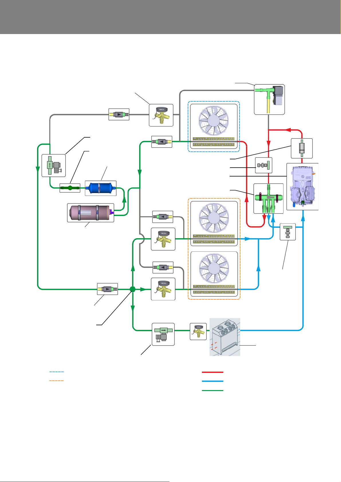
REVO-E Heat pump 4 Function and functional schematics
High pressure area / charging phase
Low pressure area / suction side
Liquid phase
Outer heat exchanger
Inner heat exchanger (passenger compartment)
Expansion valve
Filter dryer
Receiver
Check valve
4-way reversing valve
Compressor
(ADA 11123865_only)
Muffler
Solenoid valve
Sight glass
3-way distributor
Solenoid valve
Suction
sensor
High pressure sensor
pressure
Solenoid valve hot gas de-icing
Front box
4.5.1 Refrigerant circuit function schematic of the heat pump in the Cooling Mode
Fig. 413 Refrigerant circuit function schematic of the heat pump in the Cooling Mode
418
Page 34
REVO-E Heat pump 4 Function and functional schematics
High pressure area / charging phase
Low pressure area / suction side
Liquid phase
Outer heat exchanger
Inner heat exchanger (passenger compartment)
Expansion valve
Filter dryer
Receiver
Check valve
4-way reversing valve
Compressor
(ADA 11123865_only)
Muffler
Solenoid valve
Sight glass
3-way distributor
Solenoid valve
Suction
sensor
High pressure sensor
pressure
Solenoid valve hot gas de-icing
Front box
4.5.2 Refrigerant circuit function schematic of the heat pump in the Heat Pump Mode
Fig. 414 Refrigerant circuit function schematic of the heat pump in the Heat Pump Mode
419
Page 35
REVO-E Heat pump 4 Function and functional schematics
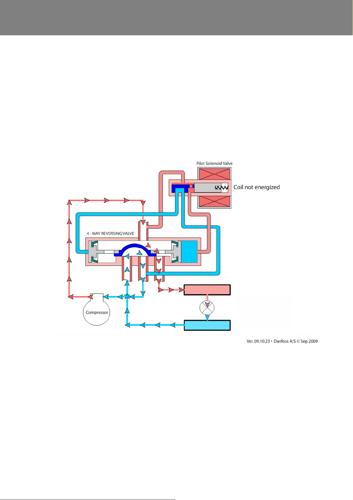
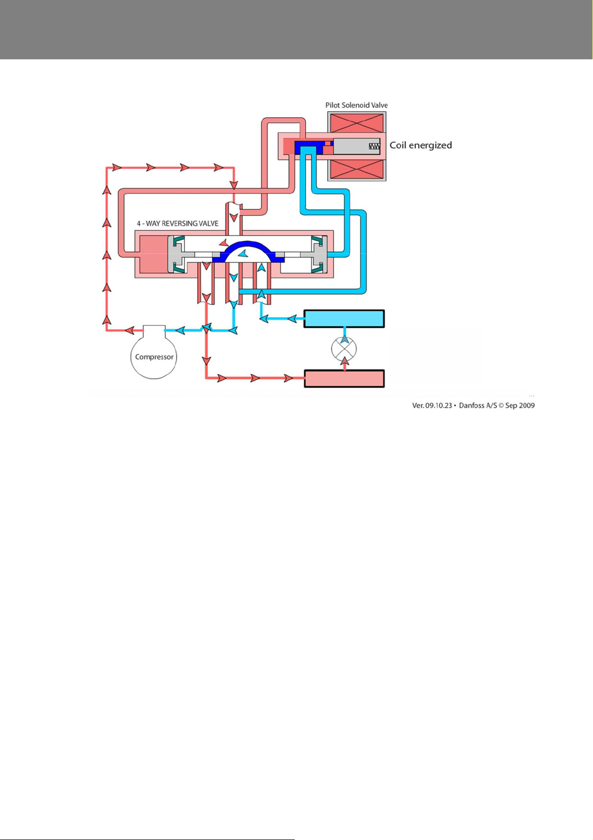
4.5.3 4-way reversing valve function schematic
Depending on the position, the 4-way reversing valve
activates air conditioning or heat pump opera tion .
4.5.3.1 Air conditioning mode
See Fig. 415.
The 4-way reversing valve is in zero position (not swit-
ched). The system is working in air-conditioning mode.
4.5.3.2 Heat Pump Mode
See Abb. 416.
The 4-way reversing valve is in heat pump mode (swit-
ched). The system is in heat pump mode. The refrigerant
circuit works in reverse.
Fig. 415 Function of the 4-way reversing valve - air condtioning
420
Page 36
REVO-E Heat pump 4 Function and functional schematics
Abb. 416 Function of the 4-way reversing valve - Heat Pump Mode
421
Page 37
REVO-E Heat pump 4 Function and functional schematics
High pressure area / charging phase
Outer heat exchanger
Inner heat exchanger (passenger compartment)
Expansion valve
Filter dryer
Receiver
Check valve
4-way reversing valve
Compressor
(ADA 11123865_only)
Muffler
Solenoid valve
Sight glass
3-way distributor
Solenoid valve
Suction
sensor
High pressure sensor
pressure
Solenoid valve hot gas de-icing
Front box
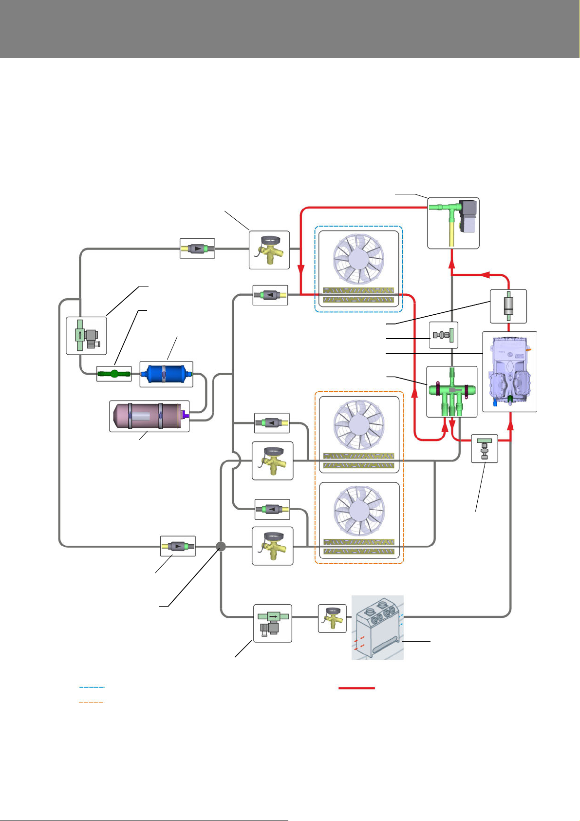
4.5.4 Refrigerant circuit function schematic of the heat pump with hot gas de-icing
(11123865_ only)
This mode is only available with the 11123865_ (additional solenoid valve) and allows the use of the system up
to an outside temperature of -5°C.
Abb. 417 Refrigerant circuit function schematic of the heat pump with hot gas de-icing (11123865_)
422
Page 38
REVO-E Heat pump 5 Troubleshooting
Potential risk to health
and life!
Warning!
High voltage!
Caution
Mortal danger!
Warning!
5 Troubleshooting
5.1 General
Follow the safety information and conditions from
Chapter 1 (see 1.6 ).
This section describes how to look for and eliminate errors
in the REVO-E air-conditioning system.
In the event of doubt, Chapters 3 and 4 contain the functional relationships.
When searching for errors and how to eliminate them, a
systematic procedure is required. The corresponding
measures for malfunctions of a general type or for deviations from desired conditions are to be implemented as
described below.
5.2 Malfunctions in the air-conditioning
circuit
5.2.3 Why the desired conditions are not
reached when testing pressure
If deviations from the desired conditions are determined
when testing the pressure, the following may have caused
this.
Pressure is too high at the high-pressure manometer
– too low air flow rate at the heat exchanger (AC opera-
tion of outer heat exchanger / HP operation => inner
heat exchanger)
– too much refrigerant
Pressure is too low at the high-pressure manometer
– too little refrigerant
– compressor speed too low (system in regular opera-
tion, maximum speed can be forced with the DCT
component test)
– defective compressor
Verify and localize these causes, service or replac e, as
needed, defective parts.
5.3 Malfunctions in the electrical system
5.2.1 Causes of malfunctions in the airconditioning system
– defective double radial blower or axial fan
– dirty or blocked air filter, dirty condenser or compres-
sor fins
– refrigerant quantity not according to specification
– defective solenoid valve ADA or solenoid valve in the
front box
– malfunctions in the expansion valve
– foreign gas in the refrigerant circuit
– insufficiently evacuated refrigerant circuit (final
vacuum <10 mbar)
5.2.2 What to do for malfunctions in the
refrigerant circuit
If errors in the refrigerant circuit appear, the system must
be inspected by a specialist and properly serviced. Do not
allow the refrigerant to release into the atmosphere under
any circumstances.
Only conduct installation, maintenance and repair
work if the motor is still and the 24V DC power s upply
as well as the high-voltage has been switched off.
Before starting work on the air-conditioning system,
ensure that the system is voltage free and make sure
it remains so for the duration of the work.
In certain cases, the following safety rules must be
followed:
– ensure the system is voltage free
– ensure system will not be reactivated
– verify system is voltage free
– ground and short-circuit
– cover or block off neighboring voltage-carrying
parts
Electrical work may only commence if protective
measures against electrical shock, short-circuits and
electric arcs have been taken.
501
Page 39

REVO-E Heat pump 5 Troubleshooting
Chapter 4 contains the functional relationships when
searching for errors.
Recognizing errors is normally limited to localizing the
defective components. The following causes of malfunctions are not considered and should be verified and eliminated if a malfunction occurs for these reasons:
• corrosion on the plugs
• loose contact
• crimping errors on the plugs or pins
• corrosion on lines and fuses
• corrosion on the battery poles
• damage to the line insulation
ATTENTION:
Search for malfunctions before replacing a fuse.
Separate the air-conditioning system from the
vehicle’s wiring system and replace the fuse while the
system is powered down.
Install a fuse of the correct size (see Chapt er 6 Wiring
plan).
Inspect the system’s functionality after elimination of a
malfunction in the vehicle.
502
Page 40
REVO-E Heat pump 5 Troubleshooting
5.4 Table of error codes
Table 501 Error codes
Valeo
codes
01 10911 ECU internal error
02 10912 PWM axial fan defective
03 10913 PWM double radial blower defective
04 10914 24V power supply too low
05 11554 External temperature signal not received >10s
06 11555 600V system status not received >10s
07 10917 Temperature of air duct / outlet temperature too high (T≥ 105°C)
08 10918 Temperature of air duct / outlet temperature too low (T≤ -40°C)
09 10919 Temperature of recirculated air / passenger cabin too high (T≥ 105°C)
10 10920 Temperature of recirculated air / passenger cabin too low (T≤ -40°C)
11 10921 Sensor value high pressure implausible high
Volvo ID Error description
12 11573 Sensor value high pressure implausible low
14 11536 Sensor value suction pressure implausible low
15 11542 System locked due to too many instances of high pressure
16 11569 System locked due to too many instances of low pressure
17 11543 Icing on heat exchanger (calculated via d etermination of suction pressure) *
18 10928 Common EDS (common error in electrical drive system)
20 11563 “Alternate charging status” signal not re ceived
23 11560 “Maxpowerallowed” signal not received
24 11548 Inverter error
32 11325 HVIL error
* In air conditioning mode only
In principle, we recommend the use of the diagnostic case
with the diagnosis software Diagnosis Control Test DCT
(see BA REVO-E Diagnostic). To diagnose the REVO-E
heat pumps SW version 3.0 must be used. It is available
for download on the website www.valeo-thermalbus.com.
Conceptually, inactive errors are only stored in the Volvo
BEA-Body error memory and can only be read out or
deleted there.
When using the Diagnosis Control Test DCT diagnostic
software, ONLY active errors in the system are emphasized in red (e.g. F01 – ECU internal).
Below is a detailed description of the errors, with the associated test procedure and possible causes.
503
Page 41

REVO-E Heat pump 5 Troubleshooting
5.5 Error codes
F01 ECU internal error
System behavior
– System not functioning & display off (GH) / LED not
blinking
or
– Display shows 'boot’ and ‘Err code’
Necessary inspections
– Test system using DCT
– Inspect the power supply of the SC620
Actions
–Replace SC620
F02 PWM axial fan defective
System behavior
– Refrigerant compressor stops during Cooling
Mode
– Axial fans do not run despite Cooling Mode being
activated
– System in Ventilation Mode despite cooling
demand from vehicle active
F04 24V power supply too low
System behavior
– double radial blowers not functioning
– Cooling Mode not functioning
– Power supply < 22V/ >10s
Necessary inspections
– Inspect 24V power supply (error active up to power
supply >28V)
Actions
– Bus servicing necessary
F05 External temperature signal not received >10s
System behavior
– Limited cooling function
– Sy stem in Cooling Mode
Necessary inspections
– Inspect external temperature sensor of bus
– Inspect CAN bus communication
Necessary inspections
– Inspect axial fans. Use the DCT from the diagnos-
tic case.
– Inspect cable harnesses according to wiring plan
– Force control of system via DCT test mode "Active
with cooling”
Actions
–Replace SC620
– Replacing axial fans NOT necessary
F03 PWM double radial blowers defective
System behavior
– Failu r e of all doub le rad ial blo we rs in sys tem
– Refrigerant compressor stops during Cooling Mode
– System in Ventilation Mode despite cooling being re-
quired in vehicle
Necessary inspections
– Inspect double radial blowers. Use the DCT from the
diagnostic case.
– Inspect cable harnesses according to wiring plan
– Force control of system via DCT test mode "Active
with cooling”
Actions
– Replace SC620
– Replacing double radial blowers NOT necessary
Actions
– a cco rd ing to Volvo do cum en tatio n
F06 600V system status not received >10s
System behavior
– Limited cooling functionality
– Sy stem in Cooling Mode
Necessary inspections
– Inspect system with DCT component test
– Inspect CAN bus communication
Actions
– a cco rd ing to Volvo do cum en tatio n
F07 Temperature of air duct / outlet temperature too
high (T≥ 105°C)
System behavior
– Limited heating functionality
Necessary inspections
– Sensor values using DCT
– Sensor resistance on the sensor / to the SC620 plug
(SC620 not connected) according to wiring plan
10kOhm 12.5kOhm 15.7kOhm
25°C 20°C 15°C
– Voltage present on sensor when SC620 and sensor
plug connected
1.36V 1.5V 1.7V
25°C 20°C 15°C
504
Page 42

REVO-E Heat pump 5 Troubleshooting
Actions
– Measured values on sensor NOK => replace sensor
– Measured values on cable harness (SC620 side)
NOK => inspects pin / replace cable harness
– Measured values on cable harness (SC620 side) OK
=> replace SC620
F08 Temperature of air duct / outlet temperature too
low (T<= -40°C)
System behavior
– Limited heating functionality
Necessary inspections
– Sensor values using DCT
– Sensor resistance on the sensor / to the SC620 plug
(SC620 not connected) according to wiring plan
10kOhm 12.5kOhm 15.7kOhm
25°C 20°C 15°C
– Voltage present on sensor when SC620 and sensor
plug connected
1.36V 1.5V 1.7V
25°C 20°C 15°C
Actions
– Measured values on sensor NOK => replace sensor
– Measured values on cable harness (SC620 side)
NOK => inspects pin / replace cable harness
– Measured values on cable harness (SC620 side) OK
=> replace SC620
F09 Temperature of recirculated air / passe nger cabin
too high (T≥ 105°C)
F10 Temperature of recirculated air / passenger cabin
too low (T<= -40°C)
System behavior
– Limited cooling functionality
– Sy stem in Cooling Mode
Necessary inspections
– Sensor values using DCT
– Sensor resistance on the sensor / to the SC620 plug
(SC620 not connected) according to wiring plan
10kOhm 12.5kOhm 15.7kOhm
25°C 20°C 15°C
– Voltage present on sensor (SC620 / sensor plug con-
nected)
1.36V 1.5V 1.7V
25°C 20°C 15°C
Actions
– Measured values on sensor NOK => replace sensor
– Measured values on SC620 plug NOK => inspect pins
/ replace cable harness
– Measured values on cable harness SC620 side OK
=> replace SC620
F11 Sensor value high pressure implausible high
(evaluation of sensor signal)
(measured value Pabs > 26bar)
System behavior
– E r ror occurs after multiple switching of the high-pres-
sure safety switch
– only in combination with F18
System behavior
– Limited heating functionality
– Limited cooling functionality
Necessary inspections
– Sensor values using DCT
– Sensor resistance on the sensor / to the SC620 plug
(SC620 not connected) according to wiring plan
10kOhm 12.5kOhm 15.7kOhm
25°C 20°C 15°C
– Voltage present on sensor (SC620 / sensor plug con-
nected)
1.36V 1.5V 1.7V
25°C 20°C 15°C
Actions
– Measured values on sensor NOK => replace sensor
– Measured values on SC620 plug NOK => inspect pins
/ replace cable harness
– Measured values on cable harness SC620 side OK
=> replace SC620
In Cooling Mode:
– default value high pressure 20bar
– axial fans maximum speed
In Heat Pump Mode:
– radial blowers maximum speed
– compressor minimum speed
Necessary inspections
– Sensor values using DCT
– Check pressure with pressure gauge and calibrate
with sensor values
(Attention: sensor values are absolute va lue s)
– Sensor resistance 5.4kOhm on the sensor / to the
SC620 plug (SC620 not connected) according to
wiring plan when compressor has not been functioning for long period of time
– Voltage present on sensor (SC620 / sensor plug con-
nected) when system running
~7.4bar ~6.4bar
1.36V 1.5V
When compressor has been off for a longer time
1.7V at 15°C
505
Page 43

REVO-E Heat pump 5 Troubleshooting
Actions
– Measured values on sensor NOK => replace sensor
– Measured values on SC620 plug NOK => inspect pins
/ replace cable harness
– Measured values on cable harness SC620 side OK
=> replace SC620
F12 Sensor value high pressure implausible low
(evaluation of sensor signal)
(measured value Pabs < 0bar)
System behavior
– Error occurs after multiple switching of the low-pres-
sure safety switch (at 11123865_ virtual via software)
– only in combination with F18
In Cooling Mode:
– default value high pressure 20bar
– axial fans maximum speed
In Heat Pump Mode:
– radial blowers maximum speed
– compressor minimum speed
Necessary inspections
– Sensor values using DCT
– Check pressure with pressure gauge and calibrate
with sensor values
(Attention: sensor values are absolute va lu e s)
– Sensor resistance 5.4kOhm on the sensor / to the
SC620 plug (SC620 not connected) accordin g to
wiring plan when compressor has not been function-
ing for long period of time
– Voltage present on sensor (SC620 / sensor plug con-
nected) when system running
~7.4bar ~6.4bar
1.36V 1.5V
When compressor has been off for a longer time
1.7V at 15°C
Actions
– Measured values on sensor NOK => replace sensor
– Measured values on SC620 plug NOK => inspects pin
/ replace cable harness
– Measured values on cable harness SC620 side OK
=> replace SC620
– Check pressure with pressure gauge and calibrate
with sensor values
(Attention: sensor values are absolute va lue s)
– Plug connection to sensor
– Measurements on X854 plug
– Sensor power supply (5V)
– Sensor voltage (feedback) when compressor de-
activated
– Sensor voltage (feedback) when compressor de-
activated (2V-4V)
Note: Compressor controllable using DCT components test.
Actions
– Replace cable harness or SC620
– Replace sensor
F15 System locked due to too many instances of high
pressure
System behavior
– System locked due to too many instances of high
pressure (5x)
– Error only in combination with F18
Necessary inspections
– Sensor values using DCT (after first unlocking
system)
– If high pressure error + axial fan speed high
– Air flow at condenser (dirty condenser)
– Amount of refrigerant (according to Volvo docu-
mentation)
– If high pressure error + axial fan speed low
– Comparison of sensor value DCT with high-pres-
sure system measured with manometer
Actions
– To unlock the system, press the Gas Charging button
(above driver) for at least 15 s. System can th en be in-
spected.
– Clean heat exchanger fins
– Refill according to Volvo documentation
– Replace sensor
F16 System locked due to too many instances of low
pressure
F14 Sensor value suction pressure implausible low
(evaluation of sensor signal)
(measured value Pabs < 0bar)
System behavior
– default value 0.5bar => compressor off
– that means below the threshold low pressure
– error entry F12 + F18
Necessary inspections
– Sensor values using DCT (operating >2 bar)
System behavior
– SW low-pressure safety switch triggers => P<1.2bara
for >22 s
– After 3 times low pressure event, system locked
– Error only in combination with F18
Necessary inspections
– Sensor values using DCT (after unlocking the system
first)
– Solenoid valve with DCT components test (acoustic)
506
Page 44

REVO-E Heat pump 5 Troubleshooting
– Voltage at the solenoid valve 0V= closed / 24V open
– Pressure level in low pressure range using manome-
ter when compressor >2 bar - expansion valve OK
– Suction pressure sensor on X854 plug
– Power supply of the connected sensor (5V)
– Sensor voltage (feedback) when compressor de-
activated
– Sensor voltage (feedback) when compressor de-
activated (2V-4V)
Note: Compressor controllable using DCT compo-
nents test.
Actions
– Unlocking the system: Press and hold for at least 15
sec. the gas charging button (above the drive r). See
vehicle documentation.
System can then be inspected.
– Replace solenoid valve
– Replace expansion valve or refill according to Volvo
documentation
– Replace suction pressure sensor
F17 Icing on the inner heat exchangers in Cooling
Mode
System behavior (in Air-conditioning Mode possible
only)
– Cooling functionality temporarily limited / air-condi-
tioning system in Ventilation Mode
– Compressor turned off until deiced (<2 bar absolute
pressure for at least 15s)
Necessary inspections
– Sensor values using DCT
– Visually inspect icing on the evaporator
– Visually inspect contamination of fresh air filter
– Expansion valve (suction pressure >2 bar)
– Refrigerant level
Actions
– Defrost evaporator
– Replace fresh air filter
– Replace expansion valve(s)
– Refill according to Volvo documentation
– Inspect low pres sure safety switch
– Read off from error memory of frequency converter
(handheld reader / PC diagnostic)
– Insulation test signal line frequency converter against
its housing
Actions
– Eliminate error depending on other errors entered
– Eliminate error in frequency converter according to
EPA description (see OI REVO-E Diagnostics)
F20 “Alternate charging status” signal not received
System behavior
– Limited cooling functionality - Ventilation Mode
Necessary inspections
– Vehicle sys tem
– CAN bus communication
Actions
– Eliminate error according to vehicle documentation
F23 “Maxpowerallowed” signal not received
System behavior
– Compressor runs without limitations, sometimes very
high power usage
Necessary inspections
– Vehicle sys tem
– CAN bus communication
Actions
– Eliminate error according to vehicle documentation
F24 Frequency converter / inverter error
System behavior
– System locked - system in Ventilation Mode
Error entry after 10x F18 (Common EDS)
Note: without simultaneous high or low pressure event
(other FS)
F18 Common error in EDS (Electrical Drive System)
System behavior
– Compressor does not start
– Red LED of frequency converter is blinking
Note: No common problem of the frequency converter
Necessary inspections
– Sensor values using DCT
– Only relevant in connection with other errors
– Inspect high pressure safety switch
Necessary inspections
– Sensor values using DCT
– Read off from error memory of frequency converter
(handheld reader / PC diagnostic)
– S a fe ty ch ain (high / low pr es sure safety switch / fre-
quency converter)
– Continuity test of X854 plug Pin3 and Pin11
– Individual components of safety chain (pressure
switch)
Actions
– Replace pressure switch
507
Page 45

REVO-E Heat pump 5 Troubleshooting
– Eliminate error in frequency converter according to
EPA description (see operating instructions of diag-
nostics case)
Unlock - ignition off and wait 1 min
F32 HVIL error
System behavior
– Cooling Mode not available
Necessary inspections
– HVI L po we r usin g DCT (1 3- 19 mA)
– Other high-voltage components affected in vehicle
– HVIL "loop" in the air-conditioning system according
to wiring plan
– HVIL resistance in the system (~10 Ohm)
– HVIL resistance of system + cable harness (SC620
separated) ~11 Ohm
– HVIL power supply for vehicle according to vehicle
documentation
Actions
– Replace cable harness
– Replace SC620
– Repair according to Volvo documentation
There are two options for the diagnosis of the frequency
converter:
1. MMI handheld control device
This is sufficient for reading the fault memory, but
without precise information about the time.
=> Read out current errors of the frequency converter
=> Read out error memory (inactive errors) of the
frequency converter
2. Analysis via PC (recommended)
The expert-level diagnosis (detailed information of the
frequency converter control) can be carried out by
means of the manufacturer diagnostic software.
This is part of the DCT setup file (data CD).
=> Read out current errors
=> Read out the last 20 errors of the frequency
converter (“Time course” field)
=> All errors over lifetime incl. counter (“Counter” field)
=> Read out operating hours (600V DC power supply)
=> Possible to record data
In both cases, the frequency converter must be provided
with 600V DC. Hybrid system must be active.
508
Page 46

REVO-E Heat pump 5 Troubleshooting
5.6 Inspecting functionality of individual
components
The inspection of individual components may take the
form of a visual inspection or manual electric inspection.
In addition, electrical components can be inspected using
the DCT components test. A compilation of these can be
found in Table 503.
Details can be found in “OI REVO-E Diagnostics“ Chap.
3.5 Diagnosis Control Test.
Table 503
Components
Axial fans Speed 0 %/ 50%/ 80%/ 100%
Double radial
blowers
Compressor
Solenoid valve Position Open / closed
Low pressure
switch
High pressure
switch
1)
1), 2)
1), 3)
Measured
values
Speed 0%/ 50%/ 80%/ 100%
Speed 32%/ 50%/ 100%
Position Switched off
Position Switched off
Measurement steps
5.6.1 General visual inspection
– Inspect components for damage (cracks, deforma-
tion, seal, discoloration, etc.) and replace, as needed.
– Inspect plugs and lines for corrosion, (loss of) contact,
crimping errors, etc. and repair, as needed.
– Inspect plug contacts for corrosion and proper seat-
ing, repair as needed.
– Visually examine all electric lines (high and low volt-
age) for abrasion
5.7 Diagnosing the REVO-E units using
the Diagnosis Control Test – DCT
diagnostic software
Information about this can be found in the operating
instructions “OI REVO-E Diagnostics“, Chap. 4.
5.8 Diagnosing the frequency converter
Information about this can be found in the operating
instructions “OI REVO-E Diagnostics“, Chap, 5 / Attachment EPA instructions for searching for errors.
Position of air
valves
4-way reversing
valve
Valve de-icing Position Open / closed
1)
When switching off compressor, error F18 will be
Position Fresh air / recirculat-
ing air
Position Heat Pump / Cooling
marked for 1 min.
2)
Adjustment forces system into low pressure range
until shut off.
3)
Adjustment forces system into high pressure range
until shut off.
509
Page 47

REVO-E Heat pump 6 Wiring plan
6 Wiring diagrams
The chapter contains the wiring diagram and fuse assignment for the following systems:
• REVO-E Heat Pump
• Electrical connections electrical components
NOTE:
For the wiring diagram, keep in mind:
• All lines without information on the cross-section have
A=0.75mm
• Lines without color information = white
• Illustrations are generally without power or pressure
6.1 Electrical fuses
REVO-E Heat Pump:
2
Secured components Fuse Fuse value
Double radial blower right F1 15
Double radial blower right F2 15
Double radial blower right F3 15
Double radial blower left F4 15
Double radial blower left F5 15
Double radial blower left F6 15
Axial fan F7 20
Axial fan F8 20
Axial fan F9 20
6.2 Wiring diagram REVO-E HP
(11120816*)
Fig. 601 (pages 1 - 6) includes the wiring diagram for the
REVO-E HP
601
Page 48
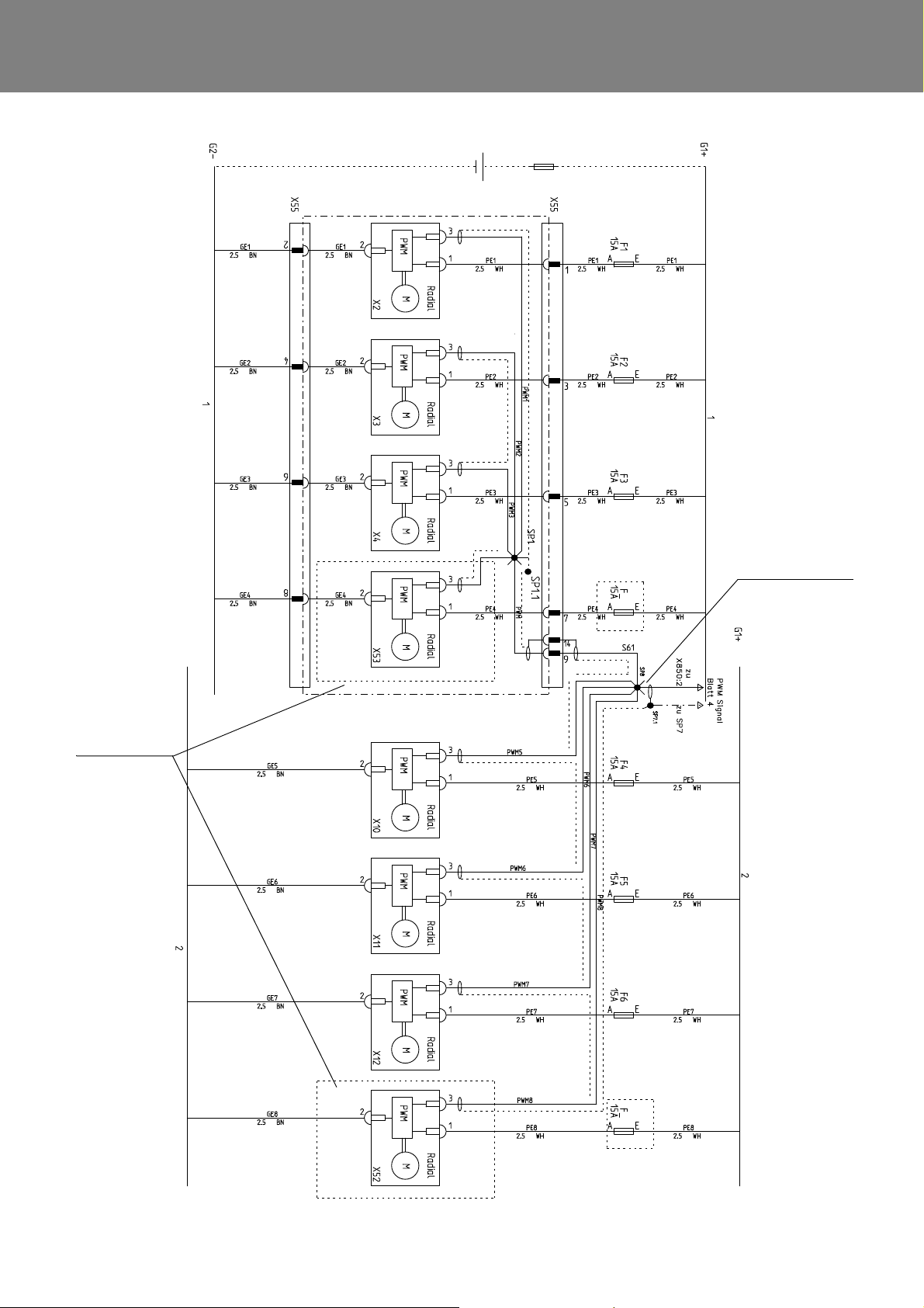
REVO-E Heat pump 6 Wiring plan
These fans will
not be used in short
run
from SP7 and SP8
PWM signal see sheet 5
Fig. 601 Wiring diagram for REVO-E HP (Sheet 1)
602
Page 49
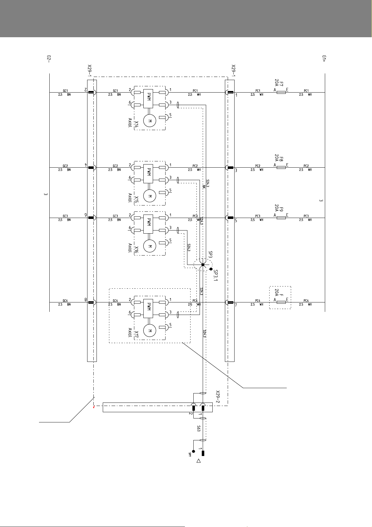
REVO-E Heat pump 6 Wiring plan
from X850 / 1 and SP7
PWM signal see sheet 5
Condenser
cable harness
This fan will not be used
in short run
Fig. 601 Wiring diagram for REVO-E HP (Sheet 2)
603
Page 50
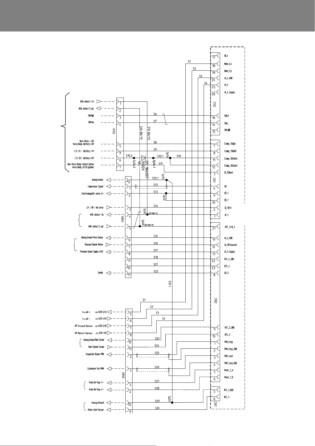
REVO-E Heat pump 6 Wiring plan
SC600
Interface X133:6
with =<10A Fuse
SC620
Fig. 601 Wiring diagram for REVO-E HP (Sheet 3)
604
Page 51
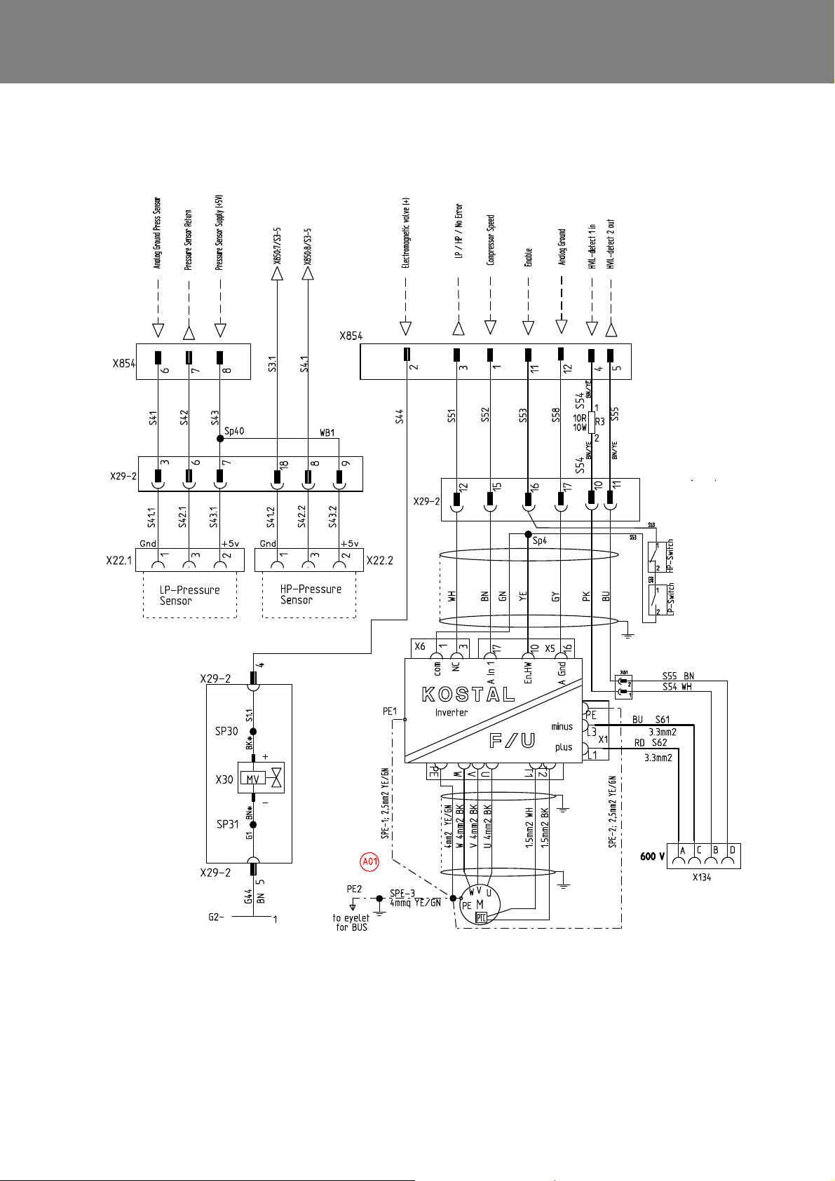
REVO-E Heat pump 6 Wiring plan
Fig. 601 Wiring diagram for REVO-E HP (Sheet 4)
605
Page 52
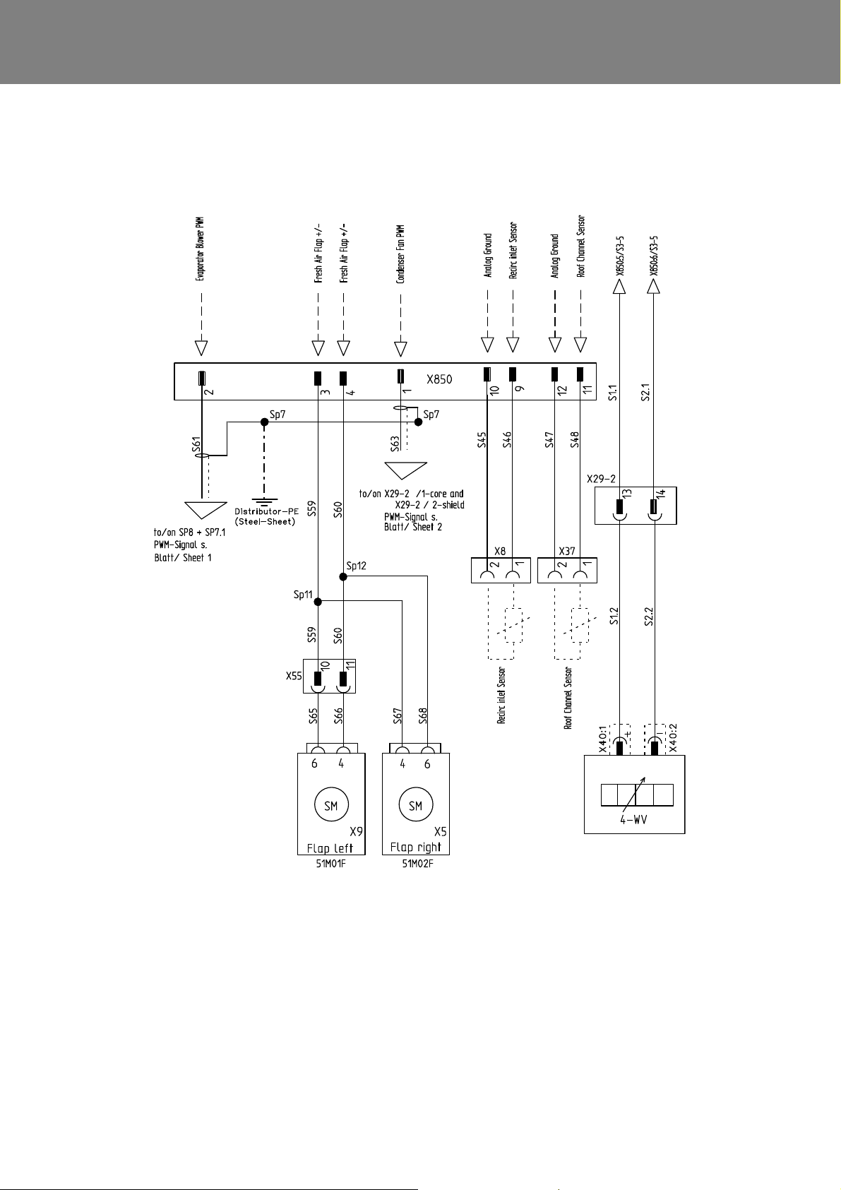
REVO-E Heat pump 6 Wiring plan
Fig. 601 Wiring diagram for REVO-E HP (Sheet 5)
606
Page 53
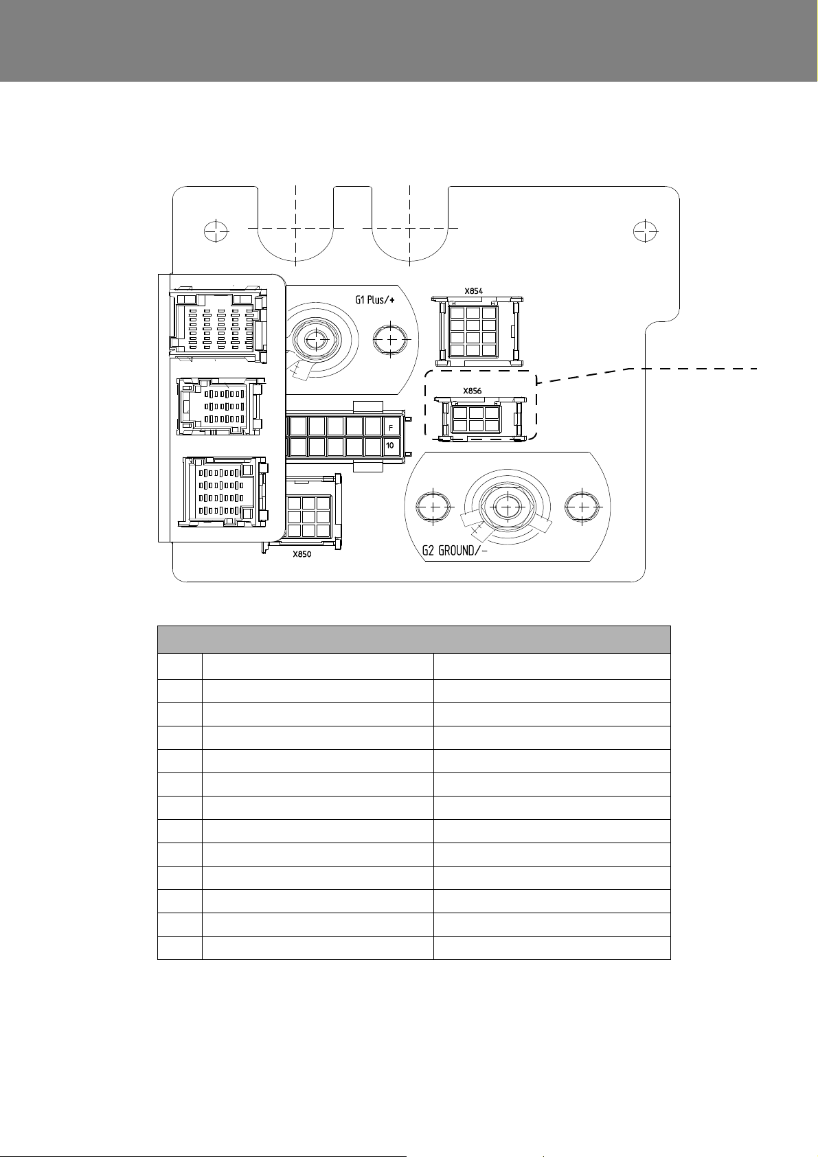
REVO-E Heat pump 6 Wiring plan
Connector will not be
used in this application
(REVO-E HP)
Connector pin assignment
Pin X854 X850
1 Compressor Speed Condenser Fan PWM
2 Electromagnetic valve (+) Evaporator Blower PWM
3 LP/HP/Drive Error Fresh Air Flap +/4 HVIL - detect 1 in Fresh Air Flap +/5 HVIL detect 2 out WV+
6 Analog Ground Press Sensor WV7 Pressure Sensor Return HP GND
8 Pressure Sensor Supply (+5V) HP Return
9 Analog Ground Recirc inlet Sensor
10 Cooling Liquid Temp Sensor Analog Ground
1 1 Enable Roof Channel Sensor
12 Analog Ground Analog Ground
Fig. 601 Wiring diagram for REVO-E HP (Sheet 6)
607
Page 54

REVO-E Heat pump 6 Wiring plan
6.3 Wiring diagram REVO-E HP+
(11123865*)
Fig. 602 (pages 1 - 6) includes the wiring diagram for the
REVO-E HP+.
.
608
Page 55
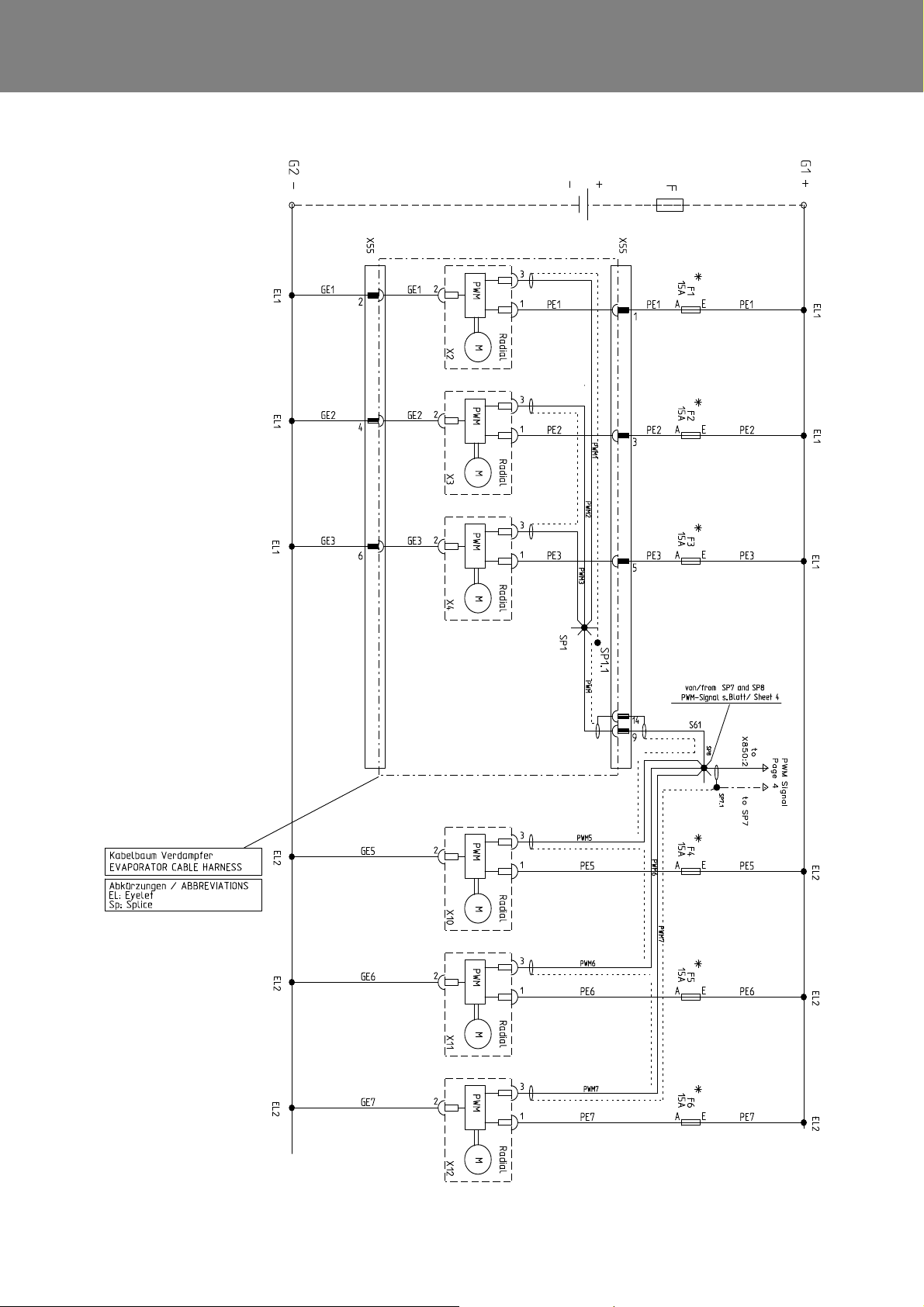
REVO-E Heat pump 6 Wiring plan
Fig. 602 Wiring diagram for REVO-E HP+ (Sheet 1)
609
Page 56
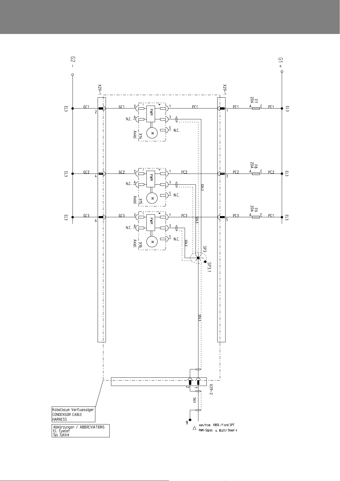
REVO-E Heat pump 6 Wiring plan
Fig. 602 Wiring diagram for REVO-E HP+ (Sheet 2)
610
Page 57
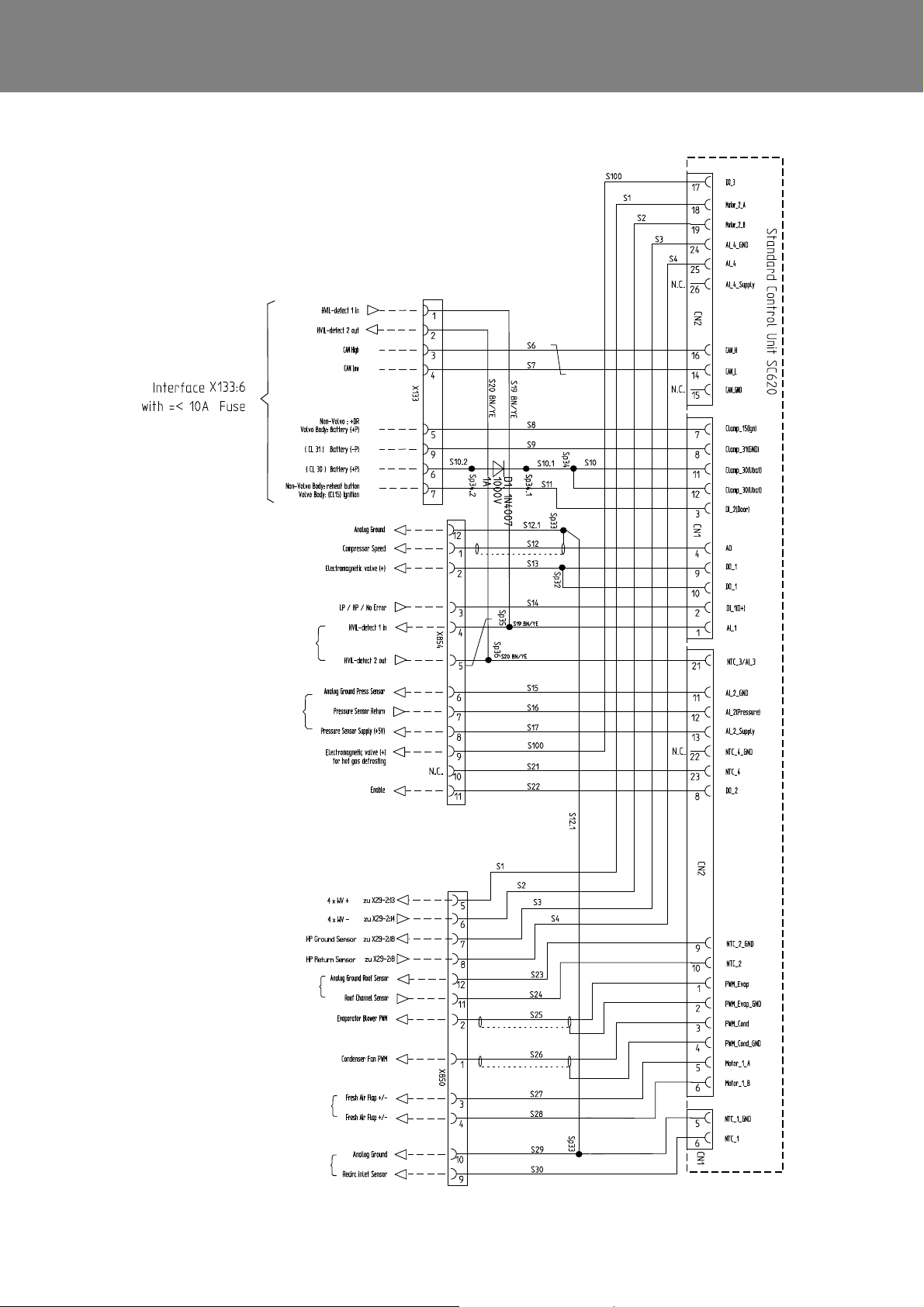
REVO-E Heat pump 6 Wiring plan
Fig. 602 Wiring diagram for REVO-E HP+ (Sheet 3)
611
Page 58
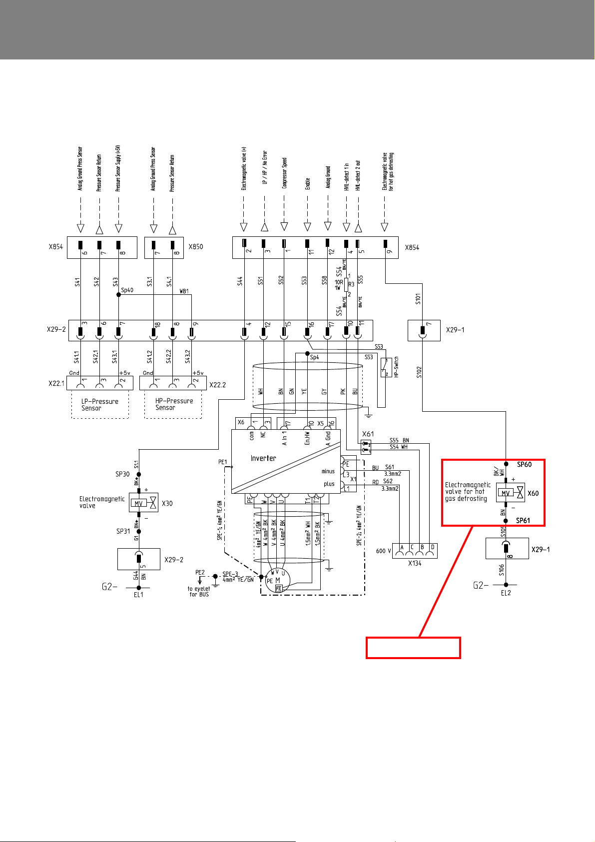
REVO-E Heat pump 6 Wiring plan
In REVO-E HP+ only!
Fig. 602 Wiring diagram for REVO-E HP+ (Sheet 4)
612
Page 59
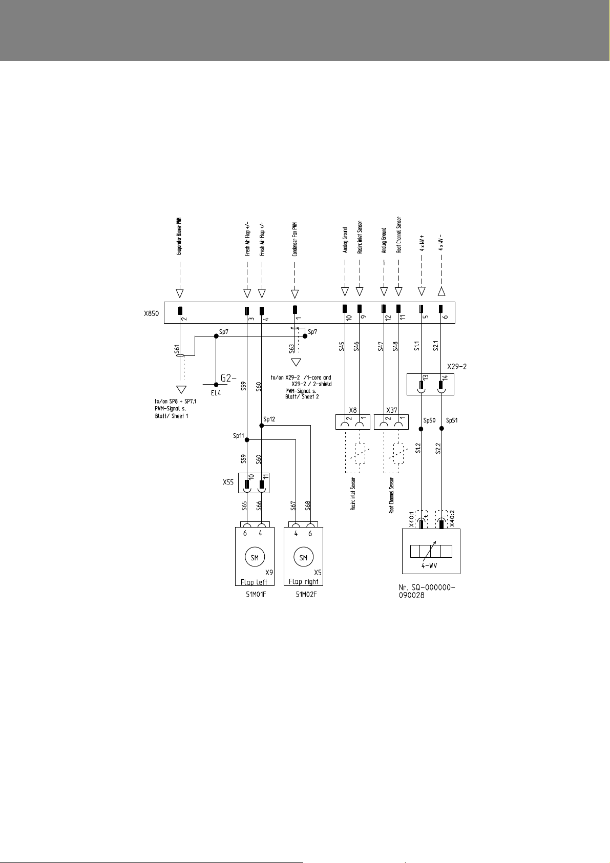
REVO-E Heat pump 6 Wiring plan
Fig. 602 Wiring diagram for REVO-E HP+ (Sheet 5)
613
Page 60
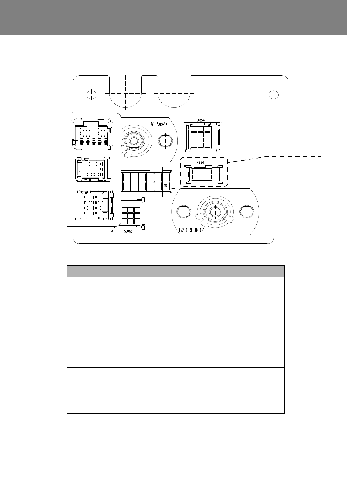
REVO-E Heat pump 6 Wiring plan
X55M
X29-1
X29-2
Connector will not be
used in this application
REVO-E HP+
Connector pin assignment
Pin X854 X850
1 Compressor Speed Condenser Fan PWM
2 Electromagnetic valve (+) Evaporator Blower PWM
3 LP/HP/No Error Fresh Air Flap +/4 HVIL - detect 1 in Fresh Air Flap +/5 HVIL detect 2 out 4WV+
6 Analog Ground Press Sensor 4WV7 Pressure Sensor Return HP Sensor GND
8 Pressure Sensor Supply (+5V) HP Sensor Return
9 Electromagnetic valve (+) for
hot gas defrosting
Recirc inlet Sensor
10 NTC4 Analog Ground
11 F/I Enable Roof Channel Sensor
12 Analog Ground Analog Ground
Fig. 602 Wiring diagram for REVO-E HP+ (Sheet 6)
614
Page 61
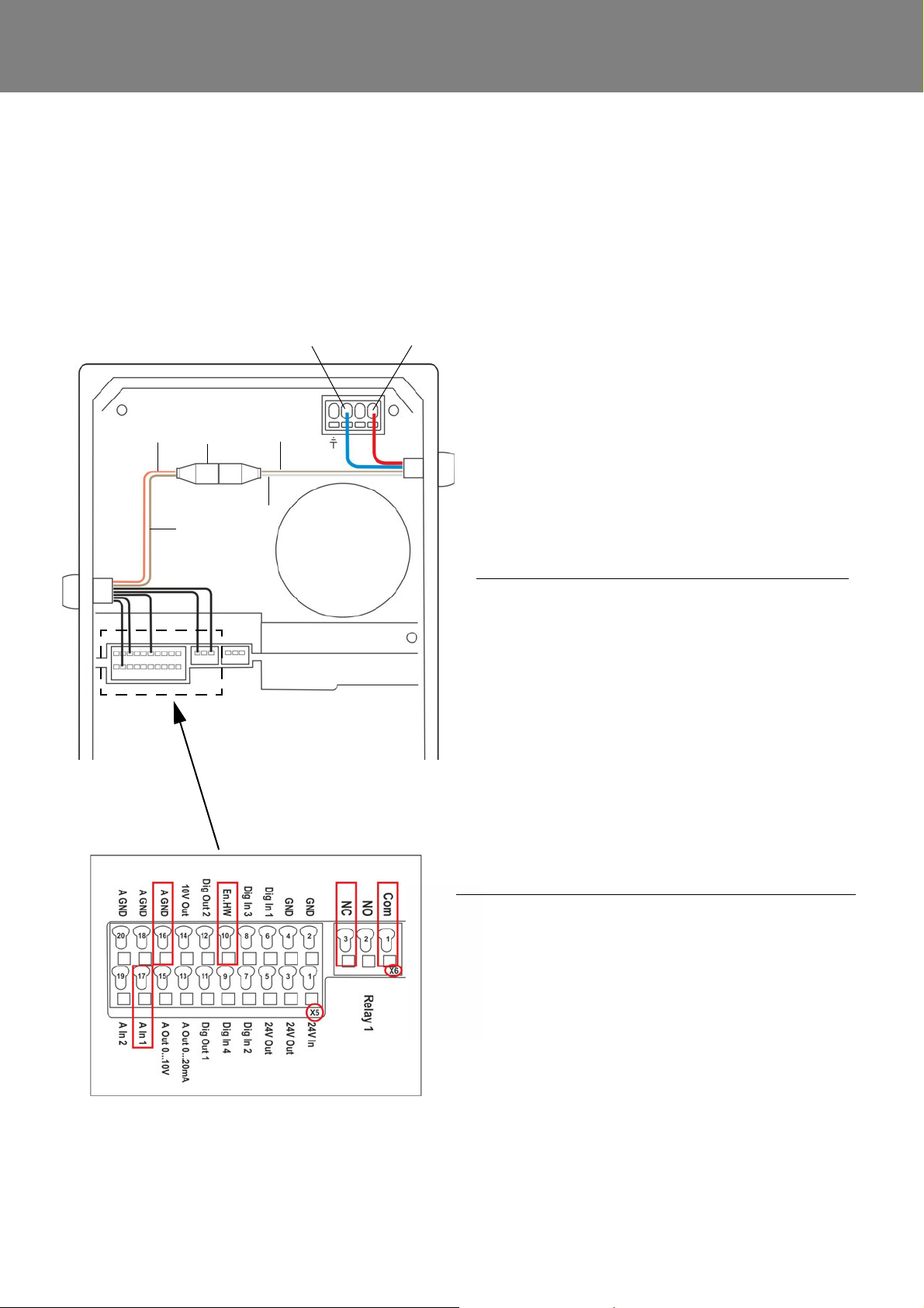
REVO-E Heat pump 6 Wiring plan
No. Designation Configura-
tion
Cable color
1 L1 DC network
(+)
Red
2 L3 DC network (-)Blue
3 HVIL in vehicle X61 Pin 1 White
4 HVIL out of vehicle X61 Pin 2 Brown
5 HVIL in system X61 Pin 1 Pink
6 HVIL out of system X61 Pin 2 Brown
4
3
5
6
7
1(L1)2(L3)
Strip No. Designation Configura-
tion
Cable
color
Cable
no.
X5 10 EN-HW Approval Yellow 4
16 A GND
(Ground 10V)
Ground Gray 3
17 A. In 1 Desired
speed of
compressor
Brown 6
X6 1 Com Center con-
tact of relay 1
Green 5
3 NC Break con-
tact of relay 1
White 7
Application map
Cable assignment for application map
6.4 Frequency converter - electrical connections
6.4.1 600V DC power supply including HVIL connector
The air-conditioning system is linked to the HVIL monitoring system via the 600V DC wiring harne ss.
Inspect the operating voltage at the connections L1 (Pos1) and L3 (Pos2) with the designated voltage tester
(CAT IV), see Fig. 603.
Fig. 603
Power supply 600V DC including HVIL connector
615
Page 62
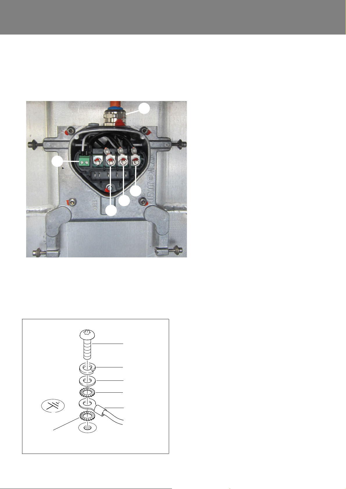
REVO-E Heat pump 6 Wiring plan
1 Connection for PTC sensor e-motor for
compressor
2 Cable connection for 400V AC cable
3 U – connection
4 V – connection
5 W – connection
6 PE (within connection plate)
Phase designations on the individual cables
must correspond to the designations on the
compressor (cover graphic).
U <-> U
V <-> V
W <-> W
2
1
3
4
5
Screw
Spring lock
Washer
Serrated lock
Ground cable
washer
washer
Serrated lock
washer
6.4.2 400V AC voltage output
The PE line as well as the lines to monitor the PTC sensor of the e-motor for the compressor are integrated into this
cable in addition to the live wires.
Fig. 604 Voltage output 400V AC
6.4.3 PE connection (potential equalizing)
In order to guarantee a secure electrical connection wh en
connecting the PE line, the order of the individual parts
must be maintained (Fig. 605).
Fig. 605
616
Page 63
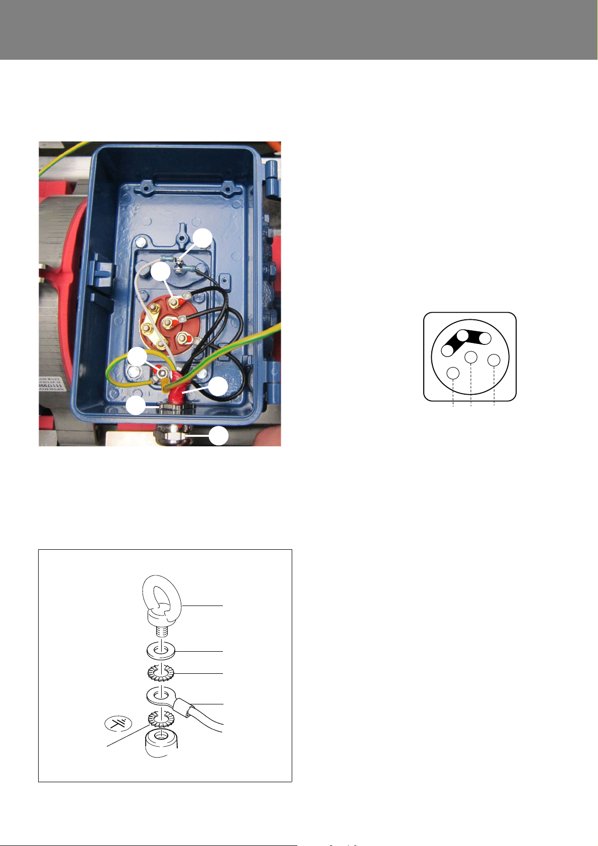
REVO-E Heat pump 6 Wiring plan
1 PE connection
2 Cable gland
3 Cable gland lock nut
4 Position marking cable
5 Phase connections for 400V AC (3)
6 Connection for PTC sensor for electrical
motor
The position marking cable must be secured
with lock nut during assembly.
Phase designations on the individual cables
must correspond to the designations on the
compressor (cover graphic).
U <-> U
V <-> V
W <-> W
PE line is connected.
Cable for PTC sensor for e-motor is plugged in.
6
5
4
3
2
1
W2
U2
V2
U1
L1 L2
L3
V1
W1
Eye bolt
Washer
Ground cable
Serrated lock
washer
Serrated lock
washer
6.5 Compressor - electrical connections
6.5.1 400V AC voltage supply
6.5.2 PE connection (potential equalizing)
Fig. 606 Voltage supply 400V AC
In order to guarantee a secure electrical connection wh en
connecting the PE line, the order of the individual parts
must be maintained (Fig. 607).
Fig. 607
617
Page 64
REVO-E Heat pump 7 Maintenance
Potential risk to health
and life!
Warning!
High voltage!
Caution
Mortal danger!
Warning!
7 Maintenance
7.1 Safety information
Follow the safety information and conditions from
Chapter 1 (see 1.6 ).
The work described in the following requires proof of
the following qualificatio ns :
See 1.6.1.
7.2 Versions of ADA
NOTE:
Most of the work described below is identical for HP and
HP + systems. Wherever there are differences, this is
explicitly stated. The information of some graphics apply
for both versions. These graphics are marked as "exemplarily".
7.3 Maintenance and upkeep
Details can be found in the REVO-E maintenance and
service plan (for the download link, see 1.5).
7.4 Inspection and maintenance
– Open the side covers of the air-conditioning syst em
and prop up with rods (attached to cover)
– Remove the coil of the solenoid valve and replace with
permanent magnet
– Siphon refrigerant via high and low pressure connec-
tions on the compressor
– As soon as the system is open, always plug the open-
ings with designated stoppers (prevents water absorption via refrigerator oil)
Follow-up work
– Exchange filter dryers
– Evacuation the air-conditioning system
– Check tightness
ATTENTION:
The maximum pressure is 17 bar, the suction pressure sensor will become damaged otherwise!
– Fill the air-conditioning system with R134a
– Remove the permanent magnet from the magnet
valve and install the coil
– Mount / close the cover
– Test functionality
– Inspect oil level after 10 minutes of running system.
7.4.1 Changing the fresh air filter
– Remove filter
– Clean filter area carefully
– Inspect heat exchanger for contamination / damages
– Insert filter
The rules in the evacuating and filling instructions for the
REVO-E apply (for the download link, see 1.5).
For work from this chapter where opening the refrigerant
circuit is required, carry out the following pr eparatio n an d
follow-up work.
Preparation work
– Vehicle / air-conditioning system powered off (primary
switch / battery disconnection switch)
– If necessary, remove protective cover for the com-
pressor / frequency converter
ATTENTION!
Note the position / direction of air flow exactly. Arrow
marks on the upper edge of the filter in the direction
of the heat exchanger.
7.4.2 Changing the filter dryer
The replacement intervals for the filter dryer are found in
the maintenance and service plan.
For removal and insertion, see Chapter 9.5.
701
Page 65
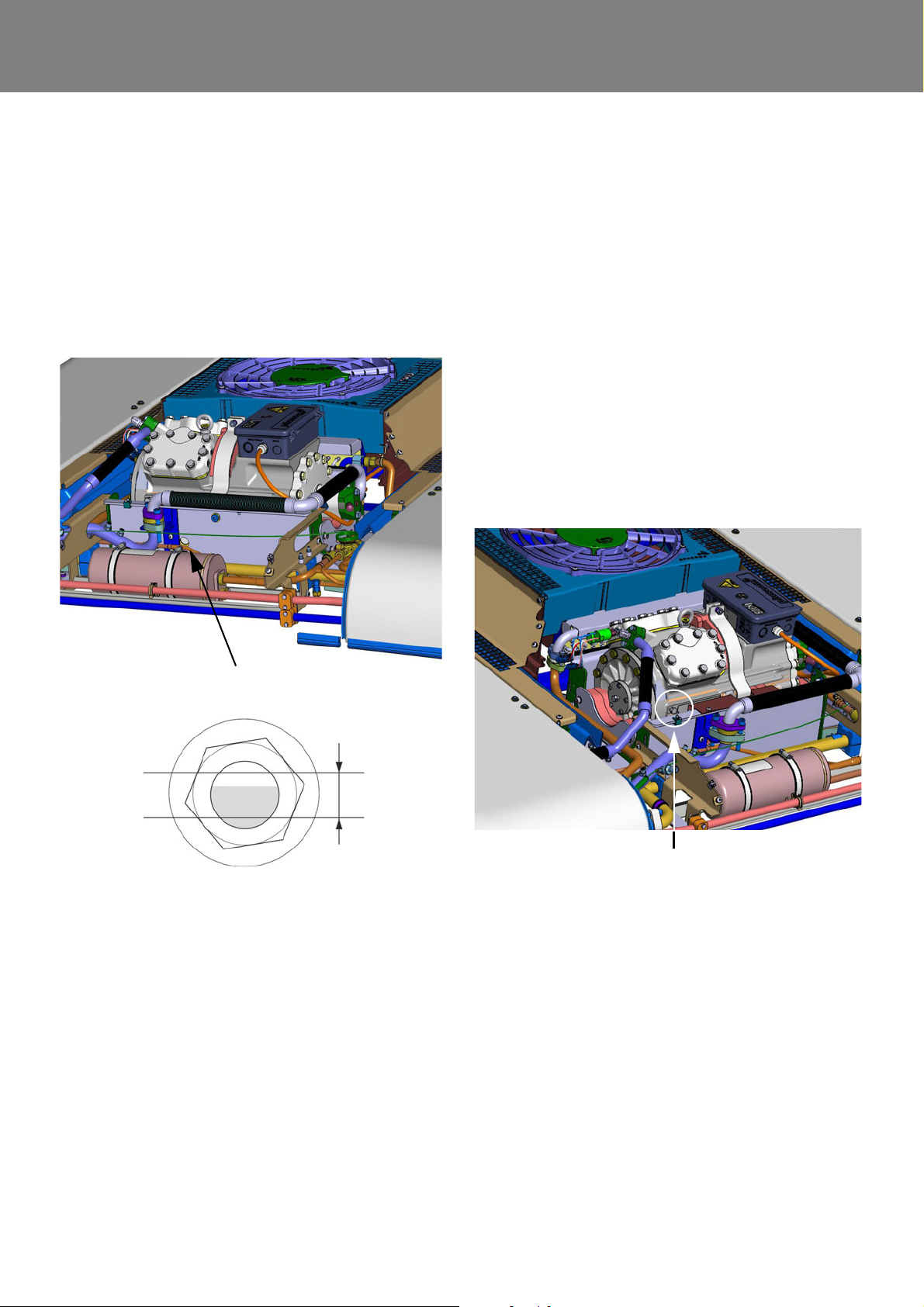
REVO-E Heat pump 7 Maintenance
Oil level
max.
min.
ca. 0.8 l
Opening for sight glass
Sight glass
Filling screw
Compressor oil
7.4.3 Inspecting the oil level of the compressor
Inspect the oil level after at least 10 minutes of running the
system.
Inspect the oil level by opening the rear side of the
compressor pan (Fig. 701).
The correct oil level is between the minimum and
maximum display Fig. 701. For deviations, see Chapter
7.4.4.
7.4.4 Changing the compressor oil
NOTE:
For this procedure, follow the preparation and follow-up
work described in 7.4.
Always change the compressor oil when conducting
servicing or repair work on the compressor.
Open the oil filling screw (Fig. 702), siphon out the old oil
and feed in the new oil.
The amount of oil to put in corresponds to the amount
taken out. The oil level, however, must be verified using
the sight glass after running the system for 10 min.
The following refrigerator oils are approved for use in th e
compressor:
– Fuchs Reniso Triton SE55
– Fuchs SEZ 32
– ICI Emkarate RL 46 S
– Mobil Arctic AL46
– Shell Clavus R 46
Fig. 701 (exemplarily)
Fig. 702 (exemplarily)
702
Page 66
REVO-E Heat pump 8 Removal/ installation of components (high-volt. syst.)
Potential risk to health
and life!
Warning!
High voltage!
Caution
Mortal danger!
Warning!
Risk of injury from falling
components of the air-conditioning system!
Warning!
8 Removal and installation
of components
(high-voltage system)
8.1 Safety information
Follow the safety information and conditions from
Chapter 1 (see 1.6 ).
The work described in the following requires proof of
the following qualificatio ns :
See 1.6.1.
It is strictly forbidden to work on high-voltage components that are under voltage! MORTAL DANGER !!
8.2 Versions of ADA
NOTE:
Most of the work described below is identical for HP and
HP + systems. Wherever there are differences, this is
explicitly stated. The information of some graphics apply
for both versions. These graphics are marked as "exemplarily".
Before beginning any work on the high-voltage
system, always make sure there is no voltage present
at the power supply of the frequency converter, using
a voltage tester (CAT IV) suitable for HV systems ( Fig.
603 Chap. 6.4)!
8.3.2 Refrigeration section
When working on the refrigerant circuit, the rules for evacuating and filling the REVO-E apply. Replace the sealing
rings from the opened connections and oil them before
replacing (refrigerator oil). If opening the refrigerant circui t
is required, the following preparation and follow-up work
must be completed.
Preparation work
– Vehicle / air-conditioning system powered off (primary
switch / battery disconnection switch)
– If necessary, remove protective cover for the com-
pressor / frequency converter
– Open the side covers of the air-conditioning syst em
and prop up with rods (attached to cover)
– Remove the coil of the solenoid valve and replace with
permanent magnet
– Siphon refrigerant via high and low pressure connec-
tions on the compressor
– Close openings of components of the refrigerant
circuit with suitable plugs (presents water absorption
by the refrigerant oil)
8.3 Preparation/follow-up
The use of a suitable and secure lifting device is required
when lifting heavy components.
Use only suitable and technically secure lifting
devices (>100kg).
Do not stand under suspended loads!
8.3.1 High-voltage system
The vehicle’s battery system must be separated by an
authorized (by the vehicle manufacturer) and trained
specialist of high-voltage systems (decommissioning). The rules provided by the vehicle manufacturer
must be followed precisely.
Follow-up work
– Exchange filter dryers
– Evacuation the air-conditioning system
– Check tightness
ATTENTION:
The maximum pressure is 17 bar, the suction pressure sensor will become damaged otherwise!
– Fill the air-conditioning system with R134a
– Remove the permanent magnet from the magnet
valve and install the coil
– Mount / close the cover
– Test functionality
Torque table, see Attachment A.
801
Page 67
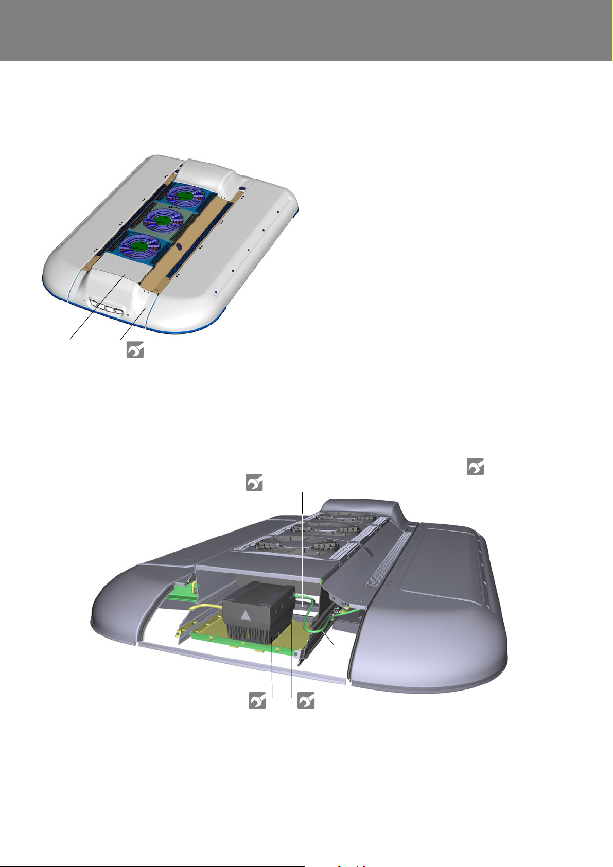
REVO-E Heat pump 8 Removal/ installation of components (high-volt. syst.)
1
2
1 Cover of the frequency converter
2 Torx screws (6)
1 Frequency converter Cover screws (4x)
2 400V AC cable
3 Diagnostic cable
4 Mount for grounding cable
5 Screws (4x) with centering cone
6 600V DC cable for power supply
See torque table
Attachment A
1
2
356
4
8.4 Frequency converter removal/ installation
8.4.1 Remove the frequency converter
Fig. 801
1. Prepare to remove the frequency converter
• Loosen the mount for th e gr ou nd in g ca ble (4) .
• Loosen the diagnostic cable (3).
• Loosen the with sealing wax secured captive cover
screws (1).
• Lift the cover, remove the grounding cable.
2. Disconnect the electrical connections of the frequency
converter.
• Check the connections L1 and L3 (Fig. 603) are
voltage free using a suitable voltage tester (CAT
IV).
• Remove power supply from the terminal strip.
• Remove the HVIL plug .
Fig. 802
802
Page 68
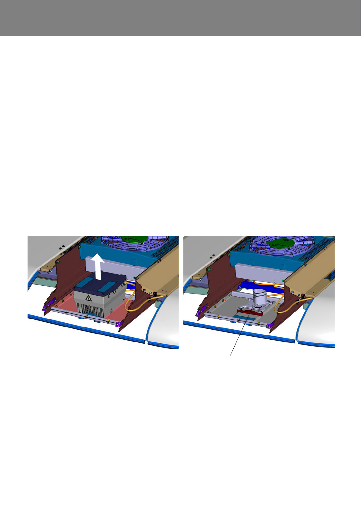
REVO-E Heat pump 8 Removal/ installation of components (high-volt. syst.)
Mounting plate of the frequency converter
• Remove cable screw for 600V DC cable (tension
relief), remove from housing.
• Remove control line s fro m term inal str i p of the
application board (Fig. 603).
• Remove cable screw for signal cable (tension
relief), remove from housing.
• Disconnect grounding cable from housing of
frequency converter.
• Loosen cone screw Fig. 802, Pos 5.
• Disassemble the frequency converter.
• Pull the frequency converter firmly up and off the
mounting plate (Fig. 803).
8.3.2 Install the frequency converter
• Ensure that connection terminals U / V / W (Fig. 604)
of the 400V AC cable for the mounting plate are
securely fastened.
• Set the frequency converter on the mounting plate
(Fig. 803), the collar of the plate will dip into opening
in the bottom of the heat sink of the frequency
converter.
• Inspect the positioning of the centering cone of the
fastening screws.
• Attach the frequency converter.
• Pull the control line cable into the housing and attach
cable gland.
• Connect control lines according to wiring diagram
Fig. 603 (chapter 6).
• Pull the 600V DC cable of the power supply into the
housing and attach cable gland.
• Connect power supply according to wiring diagram
Fig. 603 (chapter 6).
• Connect the HVIL plugs.
• Inspect the internal grounding cable to see if there is
contact with the cover.
• Install the cover using screws and secure it against
unauthorized access using sealing wax.
• Connect grounding cable according to Fig. 604.
• Connect diagnostic cable and tighten by hand.
• Install protective cover.
• Test functionality (using diagnostic as needed).
Fig. 803 (exemplarily)
803
Page 69
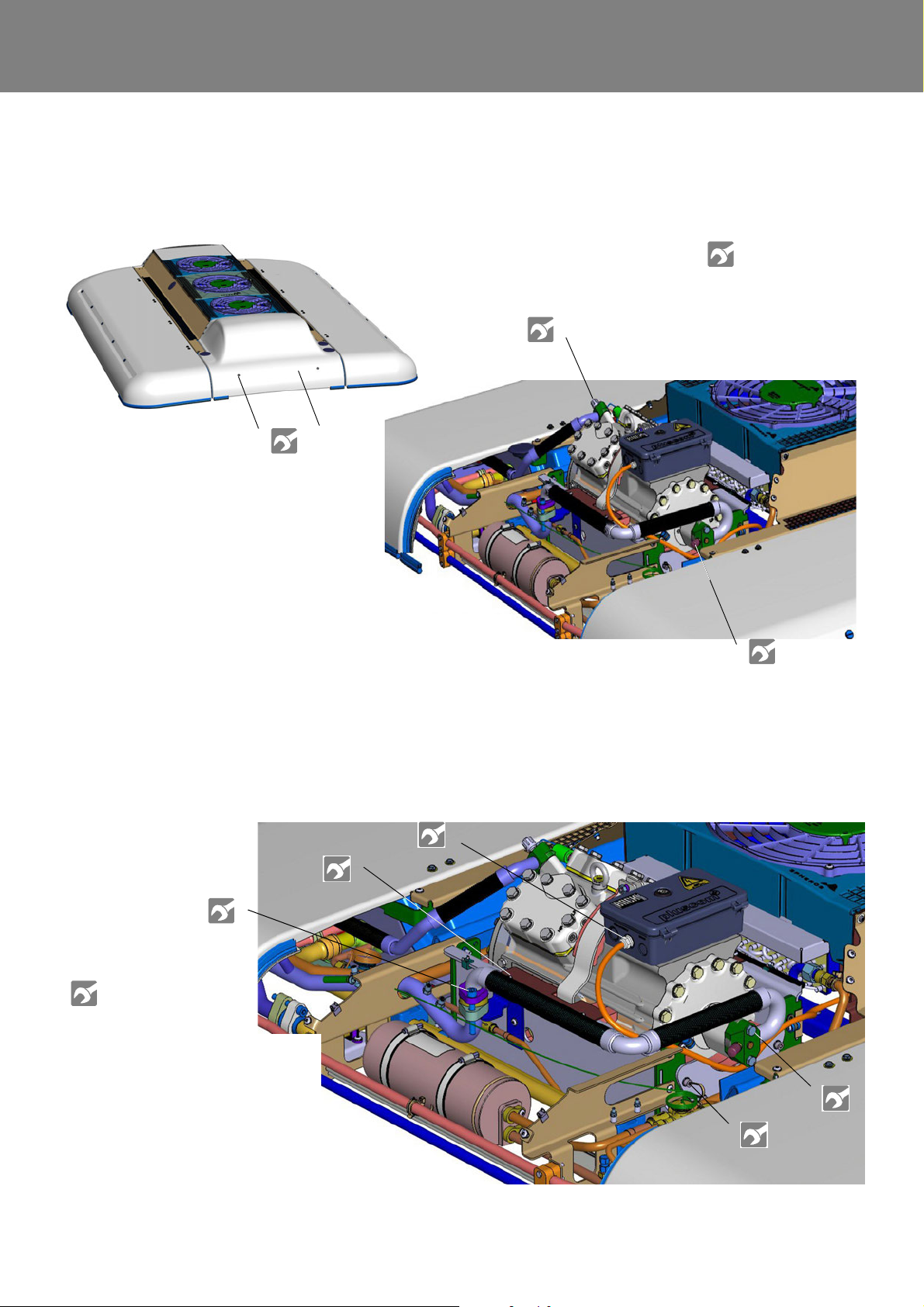
REVO-E Heat pump 8 Removal/ installation of components (high-volt. syst.)
1
2
3
4
1 Protective cover of compressor
2 Torx screws (6)
3 High-pressure / fluid connection
4 Low-pressu re / suction connection
See torque table
Attachment A
1 Cable gland for 400V AC
cable
2 Screws for retaining plate of
compressor pan (4x)
3 Screws for suction supply for
compressor (2x)
4 Screws for pressure plate on
compressor pan (4x)
5 Screws for suction pipe (2x)
1
2
3
4
5
See torque table
Attachment A
8.4 Refrigerant compressor removal/ installation
8.4.1 Remove the compressor
1. Preparation work, see 8.3.
2. Disconnecting the electrical lines
• Open the terminal box of the compressor using the
special key (attached to the compressor).
• Loosen electrical conne ctions, see Fig. 606.
Fig. 804 (exemplarily)
• Loosen lock nuts (3, Fig. 606) of the cable glands
for the 400V AC cable and pull the cable out o f the
terminal box.
Fig. 805 (exemplarily)
804
Page 70
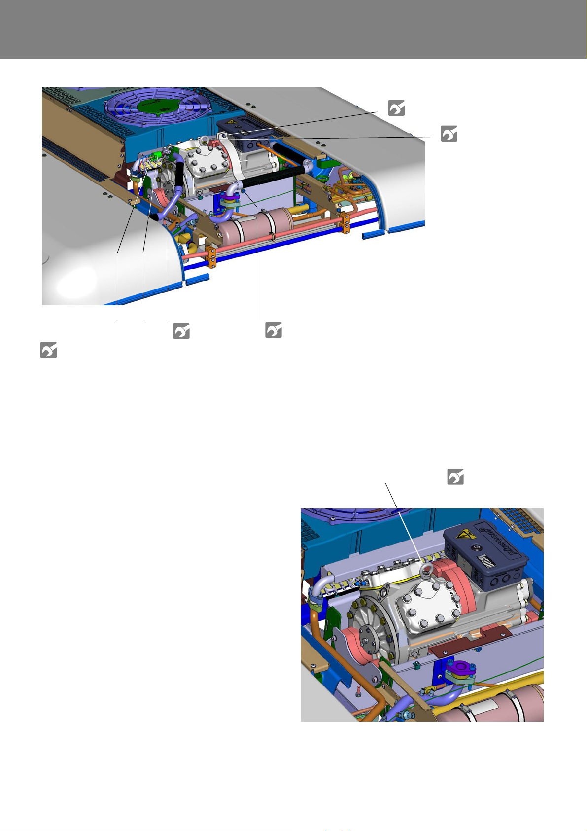
REVO-E Heat pump 8 Removal/ installation of components (high-volt. syst.)
6 Screw + locknut of mounting bracket
7 Ring screw / transport lug / grounding
8 Screws for compressor fluid lines
9 Low pressure switch (not at 11123865_)
10 Screws for mounting bracket of compressor
(both sides)
11 High pressure switch
6
7
8
9
1011
See torque table
Attachment A
Ring screw / transport lug
3. Remove attachments / connections
• Remove 24V cables from compressor pan (not
pictured).
• Remove screws (2) that attach the retaining clamp
to the compressor pan and remove retaining clamp.
• Suction line (see 9.13).
• Remove screws (4) that hold the pressure plate on
the compressor and remove pressure plates.
• Fluid line (see 9.13).
• Low / high pressure switch (see 9.12).
• Remove screws (6 and 10) that hold the mounting
bracket and remove mounting bracket.
• Separate grounding cable by pulling out ring
screws (7) from compressor housing, screw ring
screws back in.
4. Removing compressor
• Lift compressor at the ring screw (7) from
compressor pan with suitable lifting device.
Fig. 806
Ensure components of the compressor mounting do
not fall.
NOTE:
Fig. 807
805
Page 71
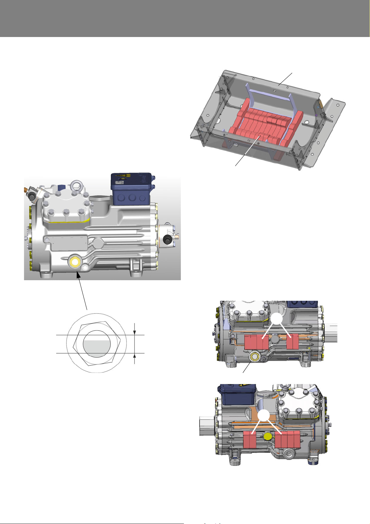
REVO-E Heat pump 8 Removal/ installation of components (high-volt. syst.)
Oil level
max.
min.
ca. 0.8 l
sight glass
1
2
1 Compressor pan
2 Absorption foam of compressor
Sight glass
3
3
8.4.2 Comparing the old/new oil level
While the air-conditioning system is being operated, some
of the compressor oil will spread in the refrigerant circuit.
The replacement compressor is already filled with 1.3 l of
compressor oil. Before replacement, compare the oil
levels of both refrigerant compressors via the sigh t gla ss
and adjust the replacement compressor as needed in
order to avoid overfilling the air-conditioning system (see
7.4.4). Note the minimum and maximum oil level.
Check, and adjust as needed, the oil level of the air-conditioning system after commissioning.
.
Fig. 809
• Lift the compressor on the ring screw with suitable
lifting device and place into compressor pan with
side foam (3, Fig. 810).
Fig. 808
8.4.3 Install the compressor
1. Set into the compressor pan
• Inspect the positioning of the foam in the
compressor pan (Fig. 809).
2. Insert and attach the compressor.
NOTE:
The sight glass oil level must be well visible when
opening the compressor pan.
Fig. 810
806
Page 72
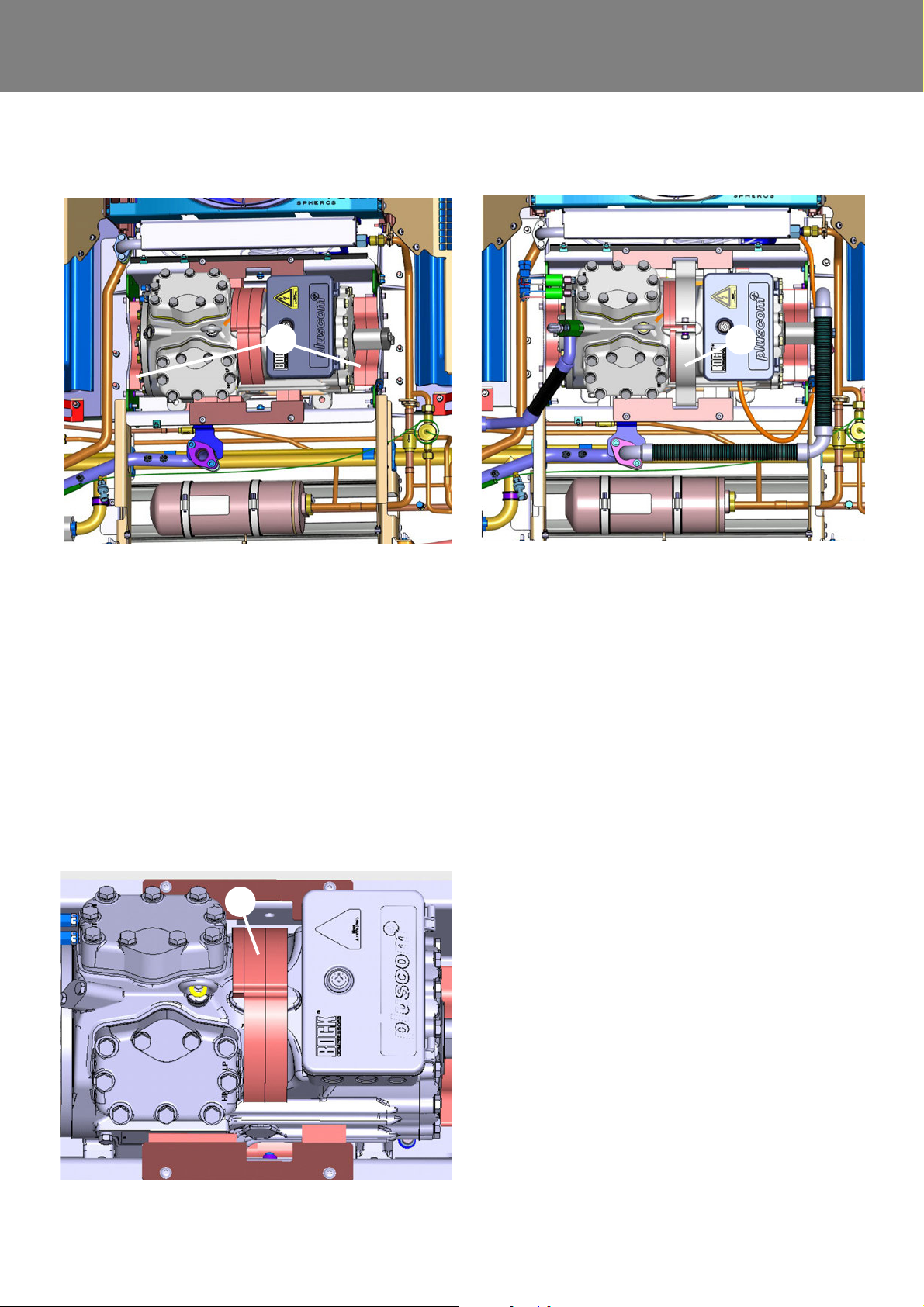
REVO-E Heat pump 8 Removal/ installation of components (high-volt. syst.)
4
5
6
• Insert foam (4, Fig. 811) on both long sides in the
compressor pan and affix with compressor pressure plate.
Fig. 811
Fig. 813
• Align foam (5, Fig. 812) on the upper side of the
compressor and reaffix compressor with mounting
bracket (6, Fig. 813). Secure screw with sealing
wax against unauthorized access.
NOTE:
Please always comply with given torque. Otherwise, the foam will lose its absorbent affect. This
causes the transference of vibration to the bus roof.
• Install mounting parts of the compressor in the
opposite order (Removing compressor, point 3.).
Use new seals when removing the refrigerant
cables.
• Lead the 400V AC cable through the opening in the
terminal box of the compressor.
• Connect the compressor to the electrical system
(see 6.5).
• Close the cap of the terminal box with the key.
Reattach the key to the compressor.
Fig. 812
807
Page 73
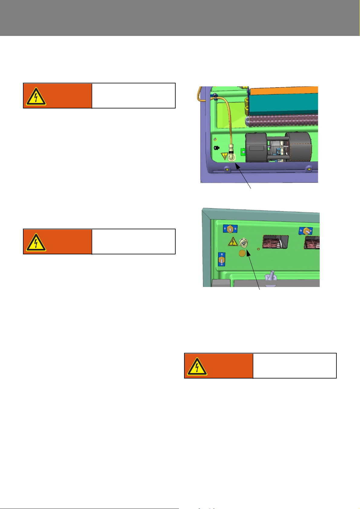
REVO-E Heat pump 8 Removal/ installation of components (high-volt. syst.)
High voltage!
Caution
Mortal danger!
Warning!
High voltage!
Caution
Mortal danger!
Warning!
600V DC plug connector in the
air-conditioning system pan: View from above
View from below (cable unplugged)
High voltage!
Caution
Mortal danger!
Warning!
8.5 600V DC/ 400V AC high-voltage cable
removal/ installation
Follow the safety information in 1.6.
8.5.1 Remove the 600V AC cable
The cable's path is described in 3.3, Fig. 3.
NOTE:
Do not replace individual components, for reasons of
safety.
1. Preparation
• Remove protect i ve cover of th e fre q ue n cy
converter, open right side cover of the air-conditioning system and prop open with bar (attached to
cover).
• Conduct work in accordance with 8.3.1 (highvoltage system).
2. Removal
• Separate vehicle connections to the REVO-E in the
vehicle’s interior.
• Uncover and disconnect the 600V DC cable on the
frequency converter (8.4.1 point 2.).
• Dismount connector of plug from pan by loosening
the lock nut on the lower side of the REVO-E (Fig.
814).
• Loosen cable clamps in the compressor pan and
pull out 600V DC cable.
8.5.2 Install the 600V DC cable
• Install cable in the opposite order. Connecting the
clamps, see 6.4.
The cable must not touch any sharp edges - abrasion hazard!
ATTENTION:
8.5.3 Remove the 400V AC cable
The cable's path is described in 3.3, Fig. 3.
NOTE:
The 400V AC cable is only preinstalled as a replacement
part on the mounting plate of the frequency converter. Do
not replace individual components.
Fig. 814 (exemplarily)
1. Preparation
• Removing the compressor (see 9.4).
• Conduct work in accordance with 8.3.1 (high-
voltage system).
2. Removal
• Disconnect the 400V AC cable from the
compressor(see 8.4.1, point 2.).
• Remove cable clamps (Fig. 815) on the
compressor pan.
• Removing the frequency converter (see 8.3.2).
• Remove the screws of the frequency converter
mounting plate.
• Loosen the attachments of the 400V AC cable to
the crossbars and remove the cable.
808
Page 74
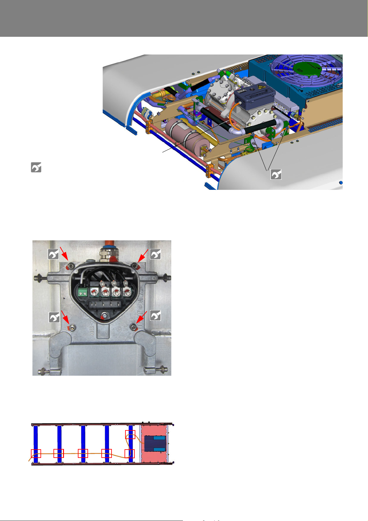
REVO-E Heat pump 8 Removal/ installation of components (high-volt. syst.)
2
1
1 400V AC cable
2 Clamps for 400V AC cable
See torque table
Attachment A
Fig. 816 Screws of the mounting plate
Fig. 815 (exemplarily)
8.5.4 Install the 400V AC cable
• Replace the plug-in holder for the 400V AC cable to
the crossbars (Fig. 817).
• Screw on the mounting plate of the frequency
converter (Fig. 816).
• Lay the 400V AC cable according to Fig. 815 and Fig.
817 and attach to the traverses and compressor pan.
ATTENTION:
The cable cannot touch any sharp edges - abrasion hazard!
• Connect the 400V AC cable to the compressor (see
6.5).
• Install the condenser (see 9.4).
Fig. 817 Moving the 400V AC cable with fixing points
809
Page 75
REVO-E Heat pump 9 Removal/ installation of components
Potential risk to health
and life!
Warning!
High voltage!
Caution
Mortal danger!
Warning!
9 Removal and installation
of components
9.1 Safety information
Follow the safety information and conditions from
Chapter 1 (see 1.6 ).
The work described in the following requires proof of
the following qualificatio ns :
See 1.6.1 under working on the refrigeration section
of the air-conditioning system.
9.2 Versions of ADA
NOTE:
Most of the work described below is identical for HP and
HP + systems. Wherever there are differences, this is
explicitly stated. The information of some graphics apply
for both versions. These graphics are marked as "exemplarily".
9.3 Preparation/follow-up
Follow-up work
– Exchange filter dryers
– Evacuation the air-conditioning system
– Check tightness
ATTENTION:
The maximum pressure is 17 bar, the suction pressure sensor will become damaged otherwise!
– Fill the air-conditioning system with R134a
– Remove the permanent magnet from the magnet
valve and install the coil
– Mount / close the cover
– Test functionality / SCT components test
Torque table, see Attachment A.
9.4 Condenser module removal/
installation
9.4.1 Removal of the condenser module
Observe the safety instructions in Cha. 8!
1. Preparation
NOTE:
The condenser module as spare part is only available as
pre-assembled unit. Replacement of individual parts is not
possible. Minimum of 2 persons is required.
When working on the refrigerant circuit, the rules for evacuating and filling the REVO-E apply. Replace the sealing
rings from the opened connections and oil th em before
replacing (refrigerator oil). If opening the conditioning
circuit is required, the following preparation and follow-up
work is required.
Preparation work
– Vehicle / air-conditioning system powered off (primary
switch / battery disconnection switch)
– If necessary, remove protective cover for the com-
pressor / frequency converter
– Open the side covers of the air-conditioning system
and prop up with rods (attached to cover)
– Remove the coil of the solenoid valve and replace with
permanent magnet
– Siphon refrigerant via high and low pressure connec-
tions on the compressor
– Close openings of components of the refrigerant
circuit with suitable plugs (presents water absorption
by the refrigerant oil)
• Do the preparation work according to 9.3.
2. Removal (Fig. 901)
• Protective grille (3)
• Refrigerant line collector - condenser (7)
• Pressure line compressor (5)
• Refrigerant line condenser - dryer (6)
• Disconnect electrical connections X29-2 condenser
wiring harness at terminal board (see Abb. 601,
Blatt 6).
• Remove wiring harness from clips.
• Remove the 24V wiring harness of the frequency
converter (see Cha. 8.4.1, step 1/2).
• Remove screws (4) securing the condenser
module.
• Lift out the condenser module by two persons.
• Close the openings of the refrigerant circuit and the
condenser module.
• Remove the axial fan (se e 9.7.3).
• Remove the wiring harness from the condenser
module.
901
Page 76
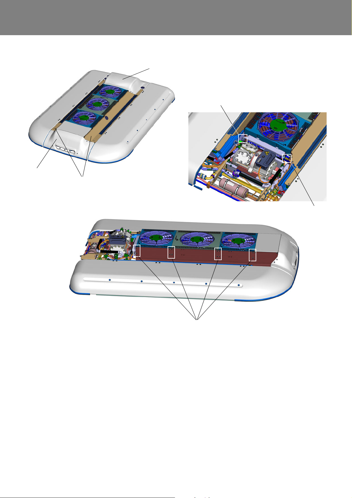
REVO-E Heat pump 9 Removal/ installation of components
1 Frequency inverter design cover
2 Compressor design cover
3 Protective grille
4 Attachment condenser module
5 Pipe pipe group 4-way reversing valv e - outer heat exchanger
6 Pipe collector - outer heat exchanger
1
3
2
5
6
4
Fig. 901 (exemplarily)
9.3.2 Installation of the condenser module
• The installation of the condenser module is carried out
in reverse order.
Thereby the gaskets of the refrigerant circuit are to be
replaced!
• Do the final work according to 9.3.
902
Page 77
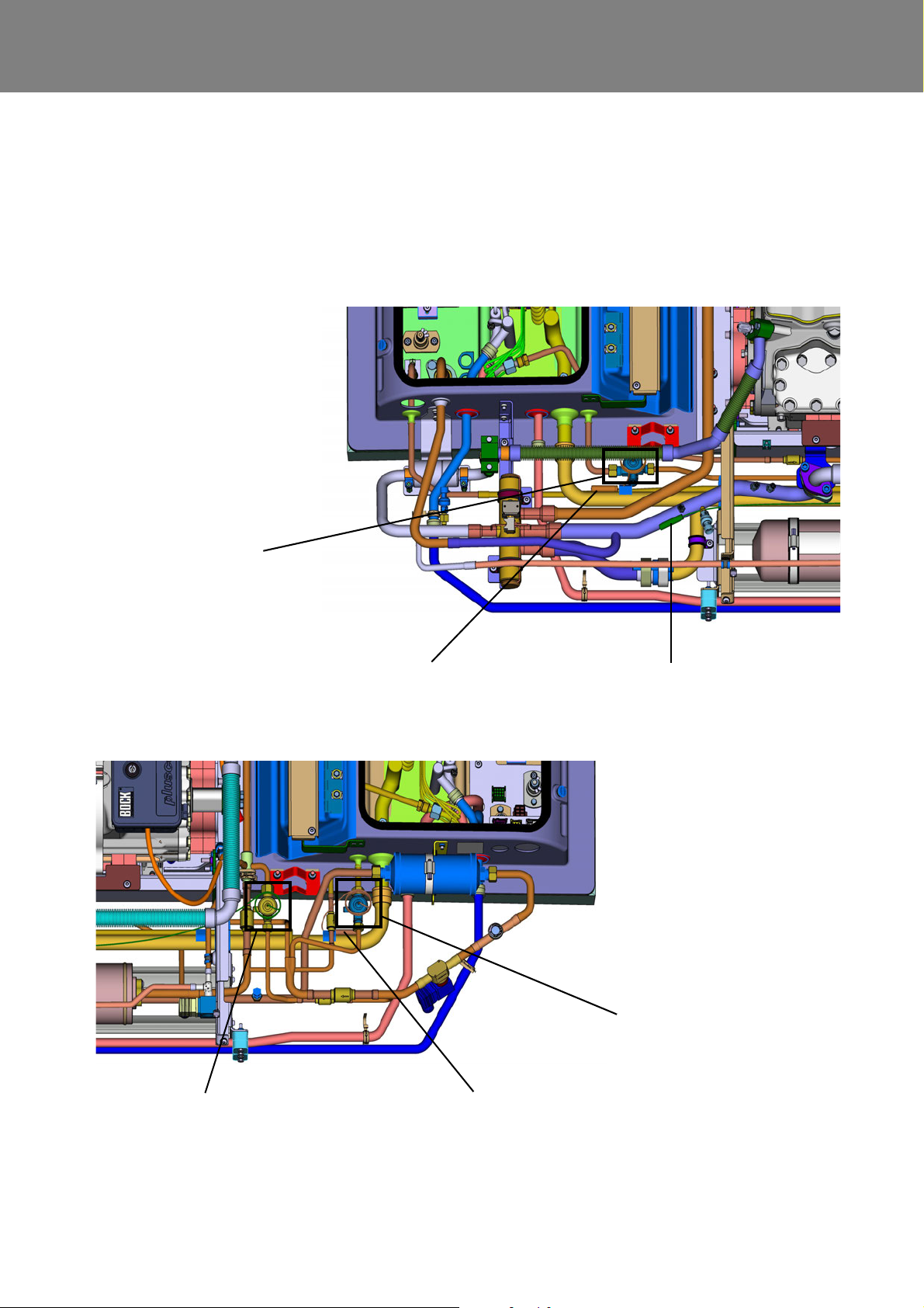
REVO-E Heat pump 9 Removal/ installation of components
Contact sensor expansion
valve outer heat exchanger
Contact sensor expansion
valve left-hand inner heat
exchanger
Expansion valve
left-hand inner
heat exchanger
Expansion valve right-hand
inner heat exchanger
Contact sensor expansion
valve right-hand inner heat
Expansion valve outer
heat exchanger
exchanger
9.4 Expansion valves removal/
installation
9.4.1 Positions of the expansion valves and the
associated contact sensors
Fig. 902 Positions of expansion valves and the associated contact sensors
903
Page 78
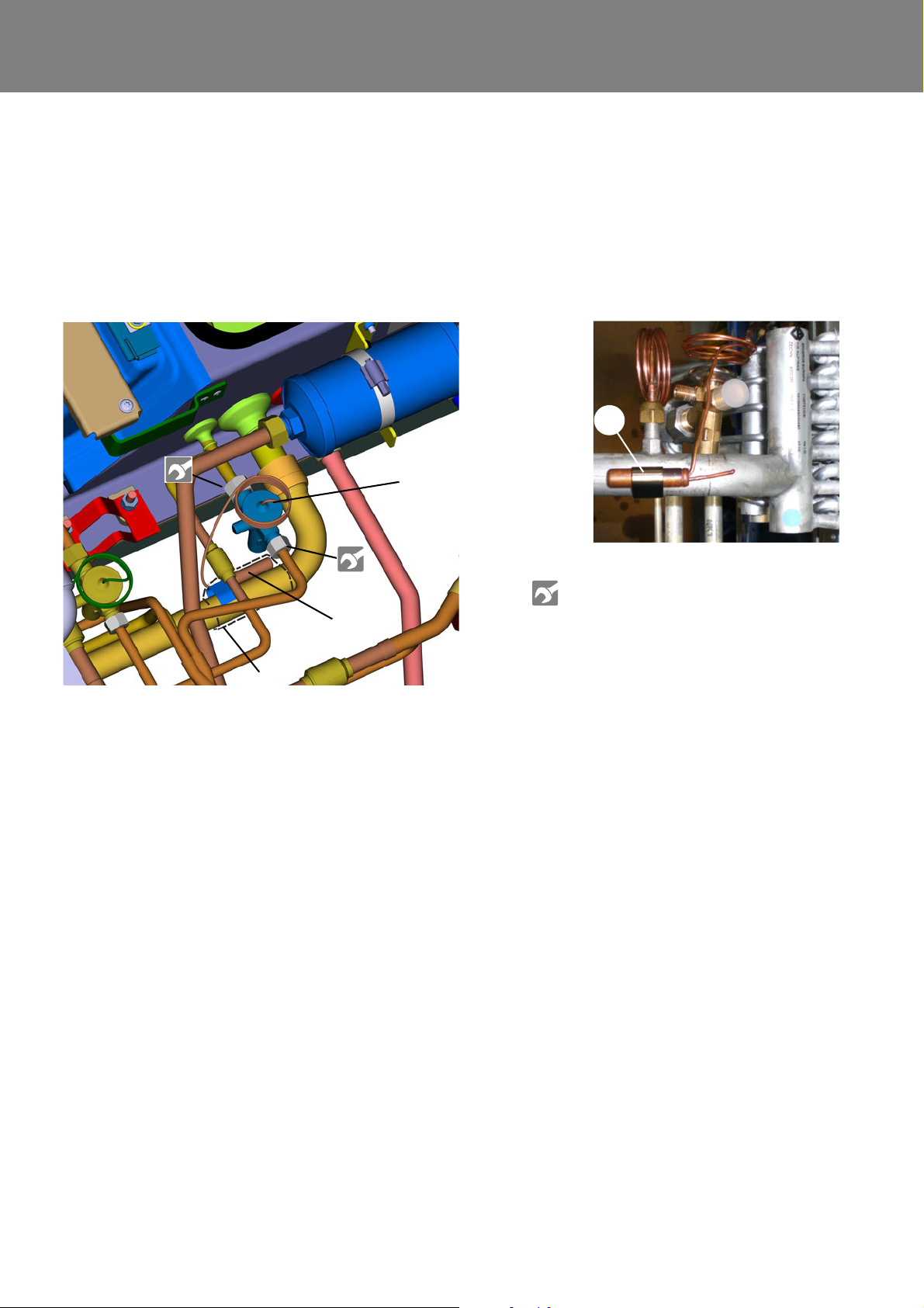
REVO-E Heat pump 9 Removal/ installation of components
1 Thermostat senso r with safety clamp
2 Expansion valve
3 Holding clamp for thermostat sensor
4 Tar binding (dashed)
3
See torque table
Attachment A
1
4
2
Fig. exemplarily
9.4.2 Remove an expansion valve
• Conduct preparation work according to 9.3.
• Remove tar binding (4) and holding clamp (3) from
thermostat sensor (1).
• Remove cap nuts from the expansion valve (2) and
remove expansion valve.
9.4.3 Install an expansion valve
• Apply refrigerator oil to sealing rings.
• Place the expansion valve (2) into the location of
installation and attach with cap nuts.
• Attach thermostat sensor (1) with holding clamp (3,
Fig. 903) and wrap with tar binding (4).
• Conduct follow-up work according to 9.3.
Fig. 903
904
Page 79
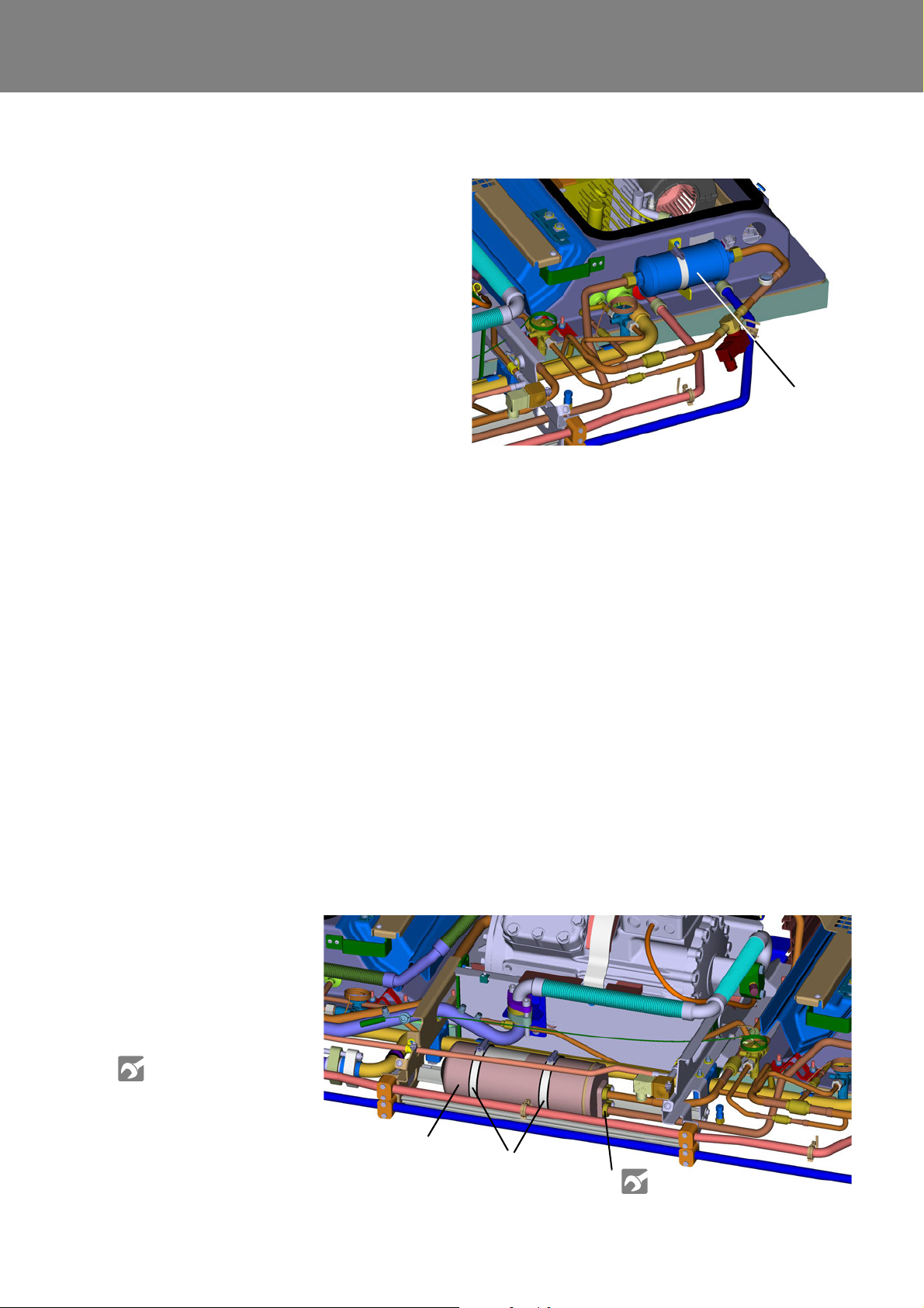
REVO-E Heat pump 9 Removal/ installation of components
Filter dryer
1
2
3
1 Receiver
2 Retaining clamps
3 SMA conne ction refrigerant tubes
See torque table
Attachment A
9.5 Filter dryer removal/ installation
9.5.1 Remove the filter dryer
• Conduct preparation work according to 9.3.
• Loosen cap nuts on filter dryer. While doing so,
prevent dryer filter from twisting with suitable tool.
• Loosen retaining clamp.
• Remove filter dryer.
9.5.2 Install the filter dryer
ATTENTION:
The arrow mark on the filter dryer (Fig. 904) must be in the
flow through direction of the refrigerant (right)!
• Apply refrigerator oil to sealing rings.
• Place the filter dryer into the location of installation
and attach with cap nuts. While doing so, prevent
dryer filter from twisting with suitable tool.
• Attach retaining clamp.
• Conduct follow-up work according to 9.3.
Fig. 904
9.6 Receiver removal/ installation
9.6.1 Remove the receiver
• Conduct preparation work according to 9.3.
• Loosen SMA connection (3, Fig. 905) of the refrigerant tube.
• Loosen retaining clamp (2).
• Remove receiver (1).
9.6.2 Install the receiver
• Replace the o-rings of the line connectors and apply
refrigerator oil
• Place the new receiver into location of installation and
orient around the position of the SMA connections.
• Attach SMA connections (3).
• Attach retaining clamp (2).
Fig. 905
905
Page 80
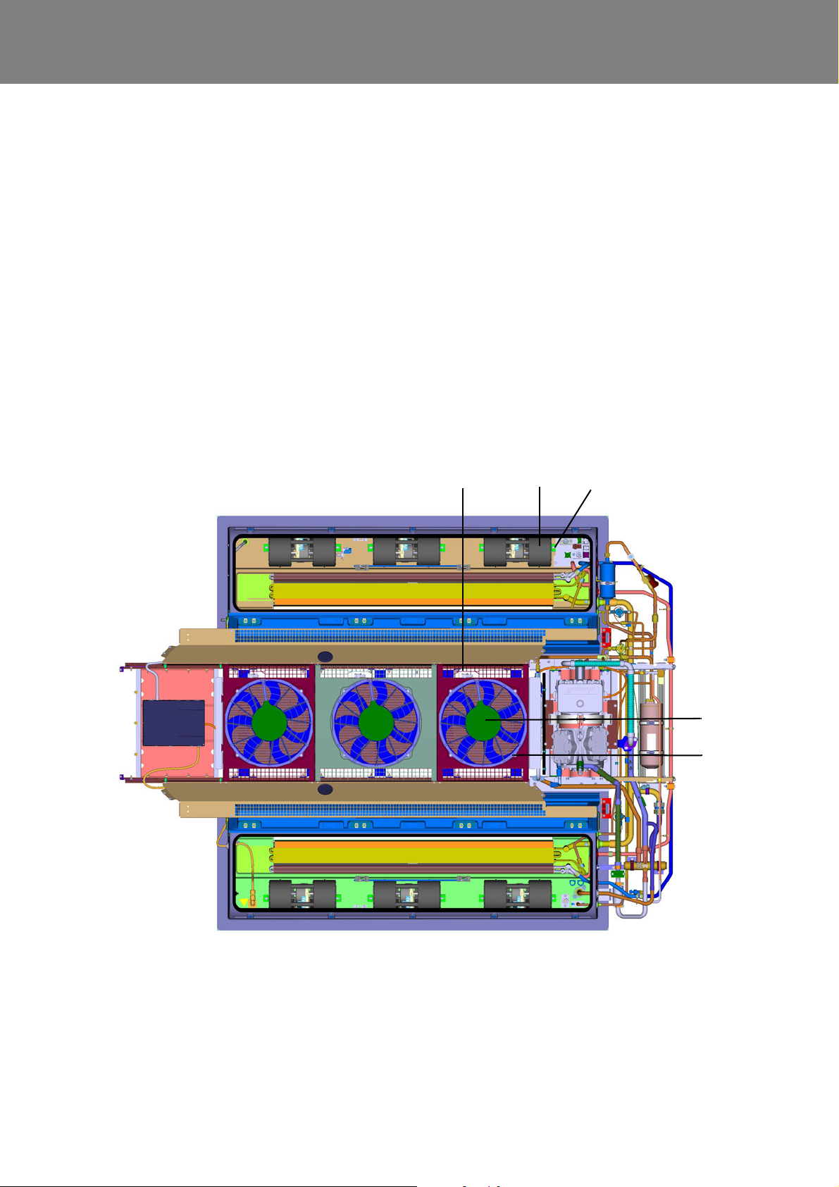
REVO-E Heat pump 9 Removal/ installation of components
1 Double radia l blower inner heat exchanger
2 Holder + screw double radial blower
3 Electric connection for double radial blower
(no figure)
4 Axial fan outer heat exchanger
5 Attachment screws axi al fan
6 Electrical connection axial fan in holder
126
4
5
9.7 Double radial blowers / axial fans
removal/ installation
9.7.1 Remove a double radial blower
• Disconnect electrical connection to the hou sing
(1, Fig. 906)
• Loosen side holders of the housing (2).
• Remove housing.
9.7.2 Install a double radial blower
• Insert housing (1) and orient.
• Attach holder (2) with screws.
• Reattach electric connection.
• Test functionality using SCT components test
9.7.3 Remove an axial fan
• Remove the electrical connection to the housing (4)
from the holder (6).
• Remove attachment screws (5).
• Remove housing (4).
9.7.4 Install an axial fan
• Insert housing (4).
• Attach housing with attachment screws (5).
• Reattach electric connection and attach in holder (6).
• Test functionality using SCT components test
Fig. 906
906
Page 81
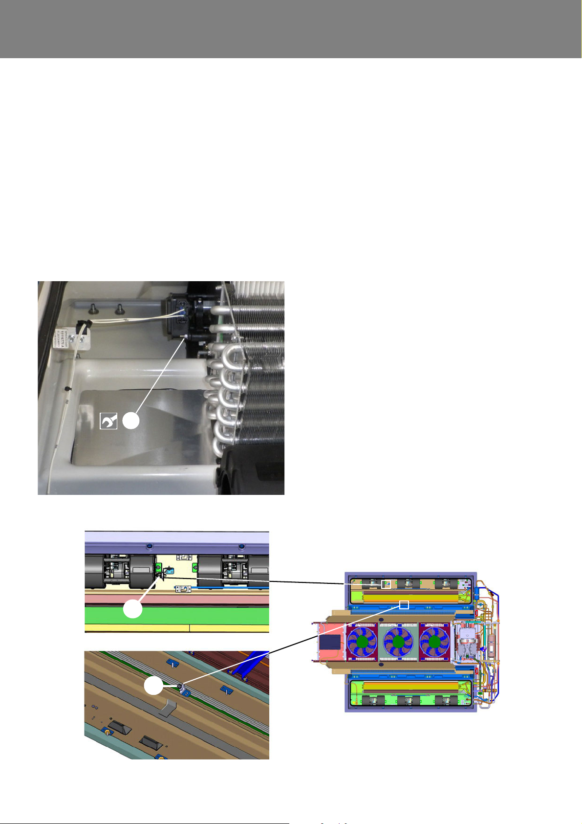
REVO-E Heat pump 9 Removal/ installation of components
1
1
2
1 - Temperature sensor, blow-out temperature
2 - Temperature sensor, passenger compartment
9.8 Recirculating air flap actuator motor
removal/ installation
9.8.1 Remove the actuator motor
• Disconnect electric connection to the motor by
removing the plug.
• Remove 3 nuts that were attached to damper mo tor
and remove damper motor (1, Fig. 907).
9.8.2 Install the actuator motor
• Place the motor into the location of installation and
attach with 3 nuts (1, Fig. 907).
• Reconnect electric connection to the motor / insert
plug.
9.9 Temperature sensor (duct / recirculating air suction) removal/ installation
Position: to the right side before the first double radial
blower.
9.9.1 Remove the duct temperature sensor
(blow-out temperature)
Position: to the right side before the first double radial
blower (1, Fig. 908).
• Loosen electrical connection on the plug.
• Unscrew sensor from holder.
9.9.2 Install the duct temperature sensor (blowout temperature)
• Screw sensor to holder.
• Reconnect electrical connection on the plug.
9.9.3
Position: in middle, right recirculating air suction inside of
air-conditioning system (2, Fig. 908).
• Remove fresh air filter, see 7.4.1.
• Loosen electrical connection on the plug.
• Unscrew sensor from holder.
Remove the recirculating air su ction temperature sensor (passenger compartment)
9.9.4
Install the recirculating air suction temperature sensor (passenger compartment)
• Screw sensor to holder.
• Reconnect electrical connection on the plug.
Fig. 907
• Insert fresh air filter, see 7.4.1.
Fig. 908
907
Page 82
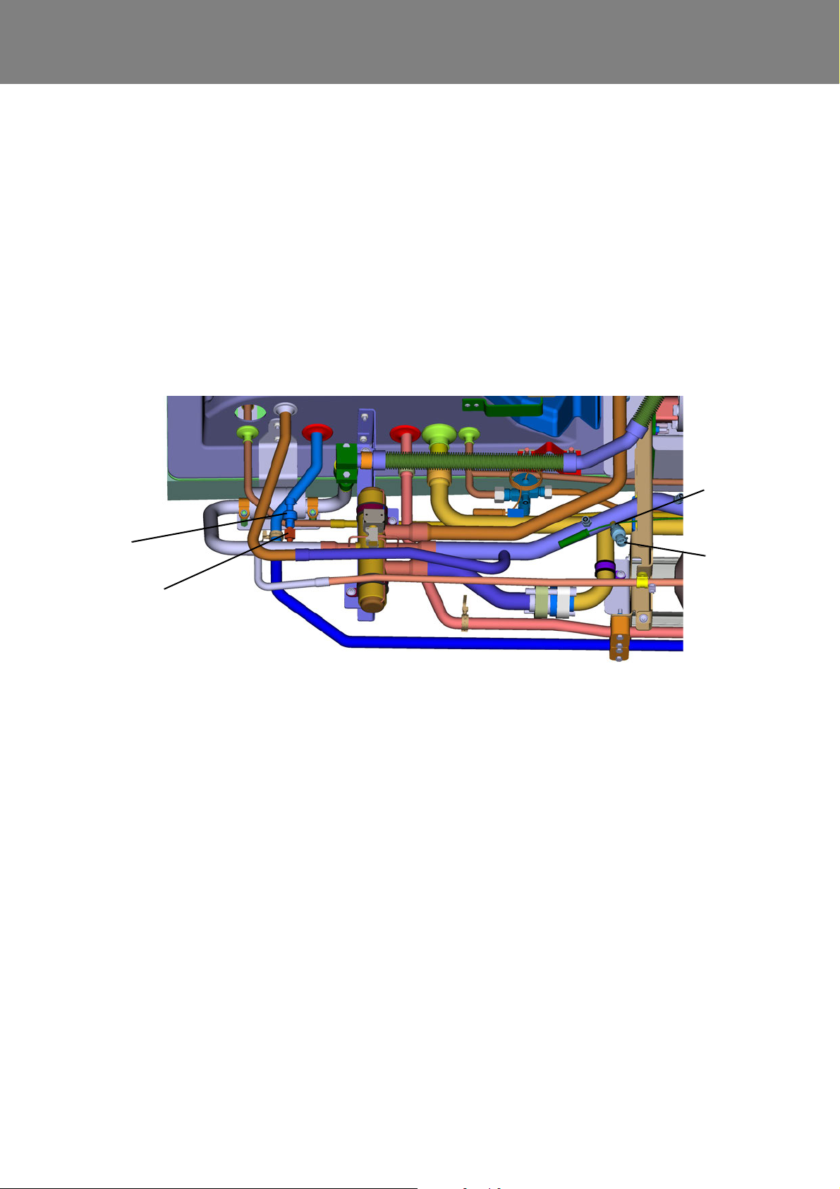
REVO-E Heat pump 9 Removal/ installation of components
1 High-pressure sensor
2 Suction pressure sensor
2 Soldering support with valve insert
1
3
3
2
9.10 Suction pressure sensor removal/
installation
There is a valve insert built into the soldering support of
the suction pressure sensor (2, Fig. 909) that automatically closes when the sensor is removed from the support.
9.10.1 Remove the suction pressure sensor
• Loosen electrical connection on the plug.
• Unscrew the sensor, holding the soldering support
with a suitable tool.
9.10.2 Install the suction pressure sensor
• Moisten sealing ring with refrigerator oil.
• Screw on the sensor, holding the soldering support
with a suitable tool.
• Reconnect electrical connection on the plug.
ATTENTION:
The maximum pressure of the leak test is 17 bar,
since otherwise the suction pressure sensor will
become damaged!
Fig. 909
9.11 High-pressure sensor removal/
installation
There is a valve insert built into the soldering support of
the high-pressure sensor (1, Fig. 909) that automatically
closes when the sensor is removed from the support.
9.11.1 Remove the high-pressure sensor
• Loosen electrical connection on the plug.
• Unscrew the sensor, holding the soldering support
with a suitable tool.
9.11.2 Install the high-pressure sensor
• Moisten sealing ring with refrigerator oil.
• Screw on the sensor, holding the soldering support
with a suitable tool.
• Reconnect electrical connection on the plug.
ATTENTION:
The maximum pressure of the leak test is 17 bar,
since otherwise the suction pressure sensor will
become damaged
908
Page 83
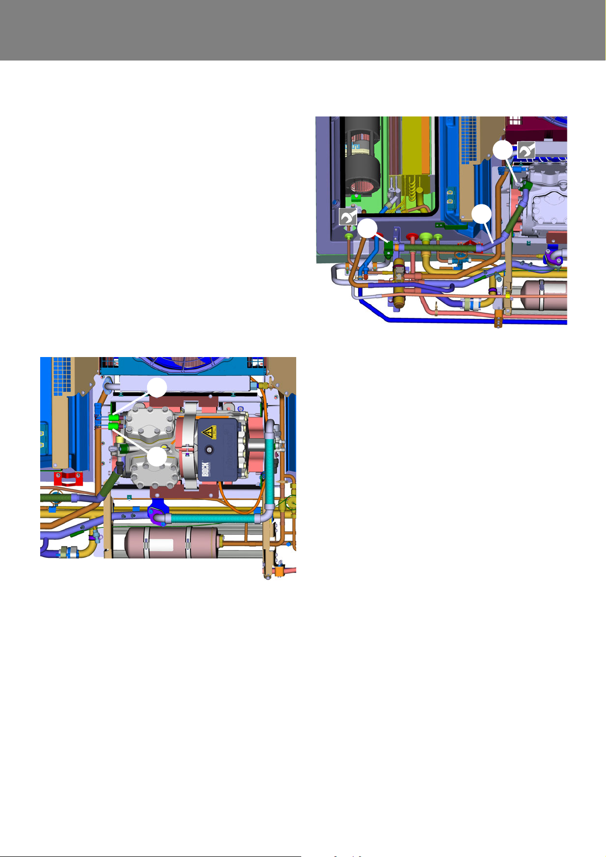
REVO-E Heat pump 9 Removal/ installation of components
1
2
1 High pressure switch
2 Low pressure switch (not at 11123865_)
1
3
2
9.12 Pressure switch removal/ installation
There are valve inserts built into the screw neck of the
pressure switch that automatically close when the sensor
is removed from the support.
9.12.1 Remove the pressure switch
• Disconnect electric connection.
• Unscrew pressure switch, holding onto the screw-in
connector with suitable tool.
9.12.2 Install the pressure switch
• Screw in new pressure switch with new copper
sealing ring, holding onto screw-in connector with suitable tool.
• Reattach electric connection.
• Lay cable, making sure there are no points of abrasion.
Fig. 910
9.13 Compressor suction and pressure
lines removal/ installation
9.13.1 Remove the pressure line
• Conduct preparation work according to 9.3.
• Unscrew filler valve (2, Fig. 911) from the pressure
line.
• Disconnect the pressure line at the SMA connection
(3) from the 4-way valve.
• Disconnect the pressure line at the SMA connection
from the compressor and remove pressu re line.
1 Pressurized ga s line
2 Filler valve, pressure side
3 SMA connection pressurized gas line - 4-way valve
Fig. 911
9.13.2 Install the pressure line
• Put pressure line including new seals (refrigerator oil
applied) into installation position and align.
• Connect pressure line onto the compressor with SMA
connection.
• Connect pressure line onto the 4-way valve with SMA
connection (3).
• Screw filler valve (2, Fig. 911) into pressure line.
• Conduct follow-up work according to 9.3.
9.13.3 Remove the suction line
• Conduct preparation work according to 9.3.
• Unscrew filler valve (2, Fig. 912) from the suction line.
• Separate connections of the suction line (1) and
remove suction line.
9.13.4 Install the suction line
• Put suction line (1) including new seals (refrigerator oil
applied) into installation position and align.
• Connect both sides of the suction line.
• Screw filler valve (2) into the suction line.
• Conduct follow-up work according to 9.3.
909
Page 84
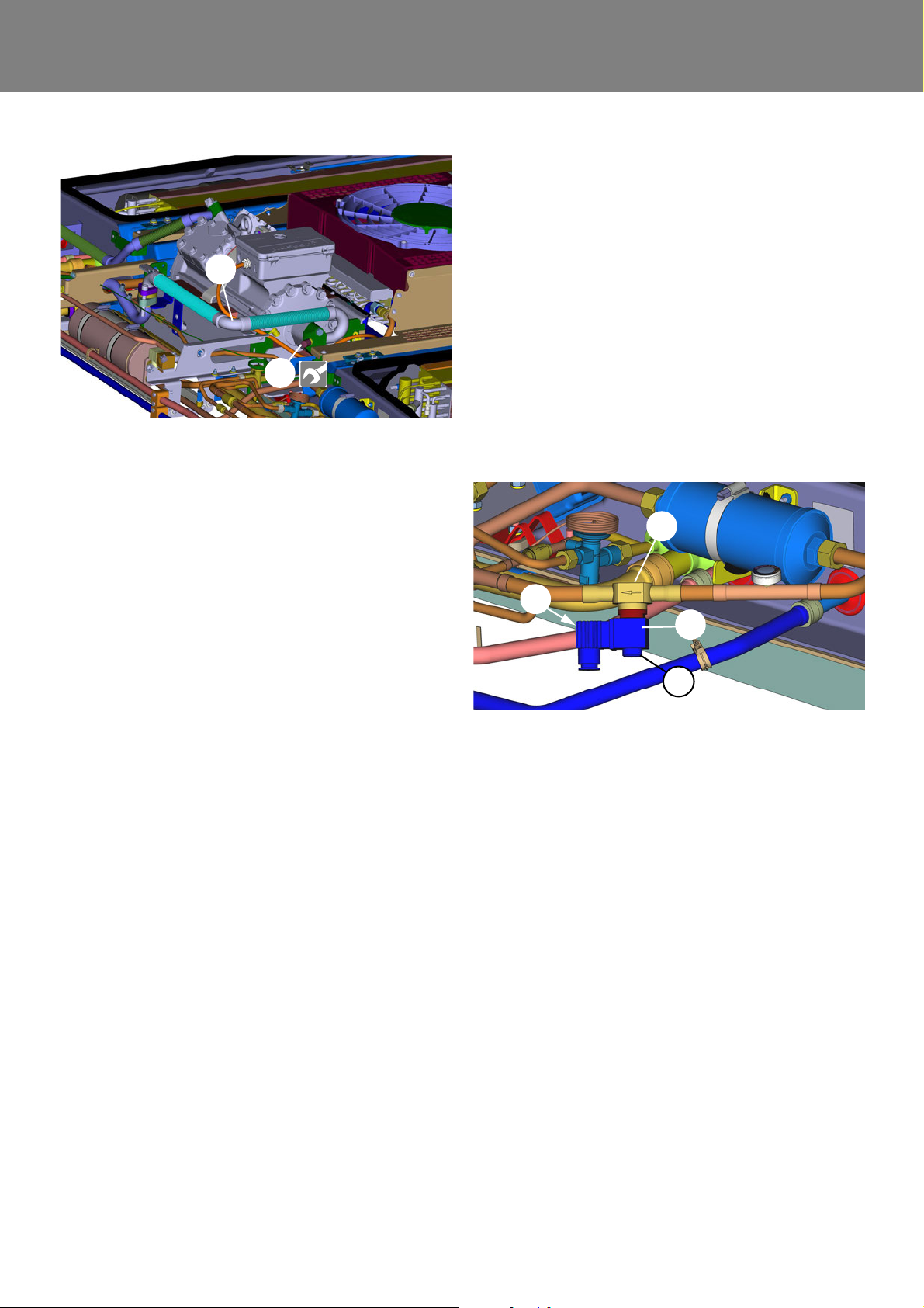
REVO-E Heat pump 9 Removal/ installation of components
1
2
1 Suction line
2 Filler valve, suction side
1 Solenoid valve with sight glass
2 Coil of solenoid valve
3 Knurled nut for coil
4 Screw for connecto r housing
1
2
3
4
ATTENTION:
Always ensure the plug points with the cable side
down in order to avoid water entry into the pl ug !
9.14.3 Remove the screw-in valve
• Conduct preparation work according to 9.3.
• Remove coil, see 9.14.1.
• Loosen screw-in valve, attaching the housing with
suitable tool.
• Remove screw-in valve.
9.14.4 Install the screw-in valve
• Screw on screw-in valve.
• Install coil, see 9.14.2.
• Conduct follow-up work according to 9.3.
Fig. 912
9.14 Solenoid valve removal/ installation
9.14.1 Remove the coil
• Unscrew knurled nuts (3, Fig. 913).
• Pull the coil (2) down.
• Pull out screw of the plug housing (4) and separate the
housing from the coil.
9.14.2 Install the coil
• Plug the plug into coil (2) and attach with screw.
NOTE:
Verify seal fits correctly.
• Place coil (2) into position and secure with knurled nut
(3).
Fig. 913
910
Page 85
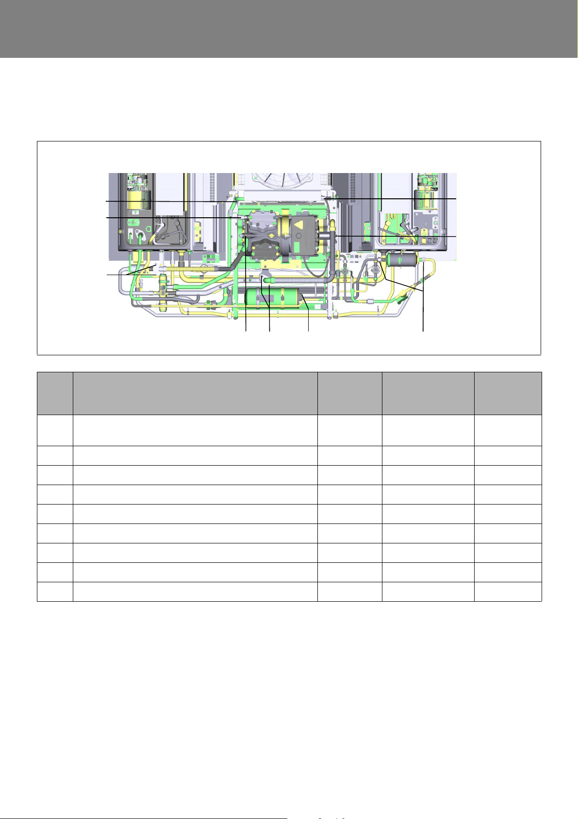
REVO-E Attachment
9
1
2
3
4
5
6
7 8
Attachment A
Tightening torques / Sealings
Item Designation Tightening
torque
in Nm
1 union nut, pressure guard, low pressure guar d ( as per
11120816_) not shown
2 screw M8x50, pressure line compressor 34 ± 10% flange seal oval 11117795A
3 screw M10x110, suction gas line compressor 50 ± 10% flange seal oval 11117795A
4 union nut SW27, outer heat exchanger 25 ± 10% O-ring 14 x 1,78 80641A
5 union nut SW27, filter drier 40 ± 10% O-ring 14 x 1,78 80641A
6 screw M6x50 9 ± 10% O-ring 26 x 2 69052A
7 nut M10, attachment suction gas line 25 ± 10% flange seal round 24632A
8 SMA connection receiver 9 ± 10% O-ring 11 x 2,5 11117038A
9 screw M8x50, outer heat exchanger 34 ± 10% flange seal round 11121059A
8 ± 10% - -
Sealing
(R134a-resistant)
Valeo ID
A-1
Page 86
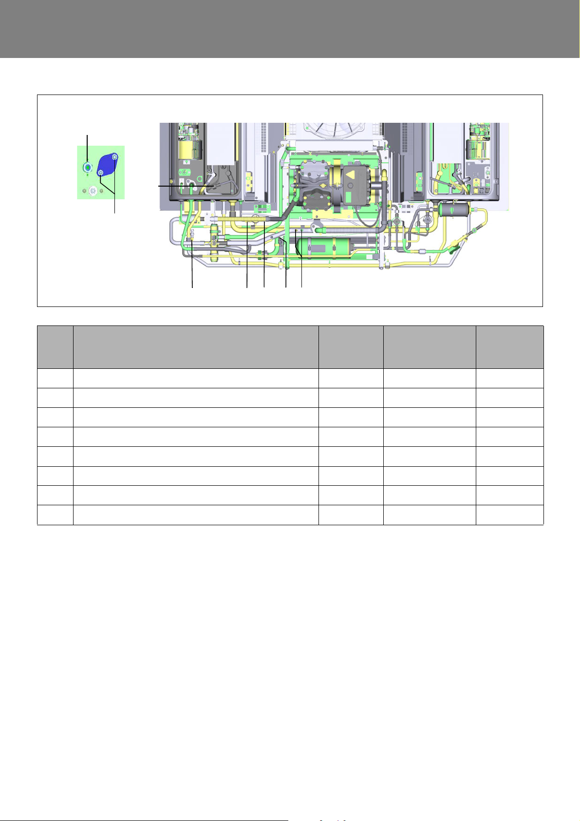
REVO-E Attachment
10 111213
14
15
16
17
Item Designation Tightening
torque
in Nm
10 union nut SW19, expansion valve inlet 17 ± 10% O-ring 7,65 x 1,78 80812A
11 union nut SW17, expansion valve compensation line 10 ± 10% O-ring 4,48 x 1,78 1103522B
12 union nut SW22, expansion valve outlet 25 ± 10% O-ring 10,6 x 1,78 80640A
13 union nut SW14, sensor high pressure 10 ± 10% O-ring 7,65 x 1,78 80812A
14 union nut SW27, liquid line front box 17 ± 10% O-ring 14 x 1,78 80641A
15 nut M10, lid suction gas line front box 50 ± 10% flange seal round 24632A
16 union nut SW27, inner heat exchanger 25 ± 10% O-ring 10,6x1,78 80640A
17 union nut SW16, sensor suction pressure 10 ± 10% - -
Sealing
(R134a-resistant)
Valeo ID
A-2
Page 87

memos
Page 88

© Valeo Thermal Commercial Vehicles Germany GmbH 2019
Valeo Thermal Commercial Vehicles Germany GmbH
Friedrichshafener Str. 7 - Tel. +49 (0)8105 7721-0 - Fax +49 (0)8105 7721-88982205 Gilching - Germany www.valeo-thermalbus.com - [email protected]
 Loading...