

Valeo ClimFill Maxi Use And Maintenance Manual
ClimFill® Maxi
Service station for air conditioning systems of
vehicles with refrigerant gas R-134a.
Use and maintenance manual
Ver. 2.0

ClimFill Maxi
CAP. 1 - CONTENTS
CAP. 1 - CONTENTS .................................................................................................................. 2
CAP. 2 - GENERAL INSTRUCTIONS............................................................................................ 4
2.1 GENERAL NOTES...................................................................................................................4
2.2 GENERAL INSTRUCTIONS .....................................................................................................4
2.3 MANUFACTURER IDENTIFICATION ......................................................................................4
2.4 MARKING ..............................................................................................................................5
CAP. 3 - SAFETY CONDITIONS.................................................................................................. 6
3.1 PERSONAL SAFETY INFORMATION ......................................................................................6
3.1.1
Definitions........................................................................................................ 6
3.1.2
Personal safety information ........................................................................... 6
3.2 IMPORTANT INFORMATION ON SERVICE EQUIPMENT SAFETY .......................................11
3.3 SAFETY DEVICES..................................................................................................................11
CAP. 4 - LAYOUT AND USE OF THE MANUAL ......................................................................... 12
4.1 USE OF THE MANUAL ..........................................................................................................12
4.2 SYMBOLS .............................................................................................................................12
4.2.1
Safety ............................................................................................................ 12
4.3 GLOSSARY...........................................................................................................................13
4.4 GUIDELINES FOR HANDLING REFRIGERANT .....................................................................14
4.4.1
Precautions for refrigerant storage............................................................. 14
4.4.2
Refrigerant conditions.................................................................................. 14
4.4.3
Recycling capacity...................................................................................... 14
CAP. 5 - GENERAL DESCRIPTION............................................................................................ 15
5.1 FRONT VIEW (EXTERIOR).....................................................................................................16
5.2 FRONT VIEW (INTERIOR) .....................................................................................................17
5.3 REAR VIEW (EXTERIOR).......................................................................................................18
5.4 REAR VIEW (INTERIOR)........................................................................................................19
5.5 RIGHT SIDE VIEW .................................................................................................................20
5.6 LEFT SIDE VIEW.....................................................................................................................21
5.7 FRONT SIDE VIEW ................................................................................................................22
5.8 TOUCHSCREEN ...................................................................................................................23
5.9 STATUS BAR..........................................................................................................................24
5.10
FUNCTION KEYS............................................................................................................26
5.11
CLIMFILL®-LOCK PATENTED TECHNOLOGY QUICK COUPLERS ...............................28
5.12
INCLUDED ACCESSORIES............................................................................................28
5.13
OPTIONAL ACCESSORIES............................................................................................29
CAP. 6 - TECHNICAL FEATURES .............................................................................................. 30
CAP. 7 - INSTALLATION........................................................................................................... 32
7.1 EQUIPMENT INSTALLATION ................................................................................................32
7.1.1
Unpacking ClimFill® Maxi.............................................................................. 32
CAP. 8 - COMMISSIONING .................................................................................................... 34
8.1 CONNECTIONS...................................................................................................................34
8.2 P
8.3 FIRST TANK FILLING..............................................................................................................36
8.4 NEW OIL BOTTLE FILLING ....................................................................................................37
8.5 DETECTION DYE BOTTLE FILLING........................................................................................38
CAP. 9 - SETUP......................................................................................................................... 39
CAP. 10 - A/C SYSTEM RECHARGE ........................................................................................ 42
10.1
10.2
OSITIONING AND ELECTRIC CONNECTIONS
REMARKS ......................................................................................................................42
NON-CONDENSABLE GAS DISCHARGE VALVE........................................................43
..............................................................................34
ENGLISH 2 / 74 CAP. 1 - CONTENTS

ClimFill Maxi
10.3
RECHARGE Q-MODE AND S-MODE...........................................................................44
CAP. 11 - AUTOMATIC CYCLES.............................................................................................. 45
11.1
AUTOMATIC A/C SYSTEM SERVICE.............................................................................45
11.2
AUTOMATIC CYCLE (BUSES) .......................................................................................45
11.2.1
Last cycle ...................................................................................................... 45
11.2.2
User-defined cycles...................................................................................... 45
11.2.3
Search parameters by vehicle registration plate number........................ 45
11.3
AUTOMATIC CYCLE (OTHER VEHICLES).....................................................................45
11.3.1
Vehicle selection from database ............................................................... 45
11.3.2
Last cycle ...................................................................................................... 45
11.3.3
User-defined cycles...................................................................................... 46
11.3.4
Search parameters by vehicle registration plate number........................ 46
11.3.5
Automatic cycle parameters configuration.............................................. 46
11.3.6
OIL TYPE REPLACEMENT................................................................................ 47
CAP. 12 - MANUAL CYCLES ................................................................................................... 48
12.1
PRELIMINARY OPERATIONS.........................................................................................48
12.2
RECOVERY....................................................................................................................48
12.3
VACUUM PHASE ..........................................................................................................48
12.4
INJECTION ....................................................................................................................49
12.5
OPERATION CONTROL (EXCLUDING BUSES).............................................................50
12.6
EMPTYING HOSES.........................................................................................................50
12.7
FLUSHING......................................................................................................................50
12.8
NITROGEN TEST.............................................................................................................51
CAP. 13 - MAINTENANCE....................................................................................................... 52
13.1
SELF LEAK TEST...............................................................................................................53
13.2
PUMP MONITORING SYSTEM SPECIAL FUNCTION - VACUUM PUMP OIL CHANGE
53
13.3
13.3.1
13.4
13.5
13.6
13.7
13.8
13.9
13.10
CAP. 14 - DISPOSAL................................................................................................................ 63
14.1
14.2
14.3
CAP. 15 - SPARE PARTS........................................................................................................... 64
CAP. 16 - MESSAGE AND ALARM CODES.............................................................................. 65
CAP. 17 - MAINTENANCE FORMS .......................................................................................... 71
DRYER FILTER CHANGE................................................................................................55
MESSAGE FOR FILTER ALMOST EXHAUSTED ................................................. 58
COUNTERS ....................................................................................................................58
VESSEL FILLING (A/C SERVICE STATION TANK) ..........................................................58
NON-CONDENSABLE GAS DISCHARGE ....................................................................59
TANK REFRIGERANT INTERNAL RECYCLING...............................................................59
SYSTEM INFORMATION ................................................................................................60
MAINTENANCE OF PRINTER ........................................................................................60
PERIODIC CHECKS.......................................................................................................60
A/C SERVICE UNIT DISPOSAL ......................................................................................63
RECYCLED MATERIALS DISPOSAL...............................................................................63
PACKAGING DISPOSAL ..............................................................................................63
CAP. 1 - CONTENTS 3 / 74 ENGLISH

ClimFill Maxi
CAP. 2 - GENERAL INSTRUCTIONS
2.1 GENERAL NOTES
All rights reserved.
This manual may not be reproduced, in part or entirely, either in printed or digital form.
It may be printed out solely for use by the user and operators of the equipment to
which it refers.
VALEO SERVICE and resources used for the drawing up of this manual will not be held
responsible for the incorrect use of the manual while they guarantee that information in
the manual have been duly checked.
The product can be subject to changes and improvements. VALEO SERVICE reserves
the right to change without notice the information contained in the manual.
2.2 GENERAL INSTRUCTIONS
Pressure equipment undergoes checks before commissioning and periodical checks
during operation in compliance with rules and law provisions in force in the country
where the equipment is used.
The operator is responsible for operating the equipment in conformity with local
legislation.
The equipment is designed for recovering and recycling R134a refrigerant fluid from
A/C systems of buses, cars and similar vehicles.
The equipment is intended to be used by repair and service garages for buses, cars
and similar vehicles.
This equipment is intended solely for use by professionally trained operators familiar with
the basics of refrigeration, refrigeration systems, refrigerants and the hazards associated
with pressurised equipment.
Careful reading of the present manual by the owners, the users and the operators is
required for a correct and safe use of the equipment.
The user shall not be entitled to open the product since maintenance operations are
reserved to the authorised service centre.
2.3 MANUFACTURER IDENTIFICATION
The ClimFill® Maxi equipment is manufactured by:
VALEO SERVICE
70 rue Pleyel Cedex
93285 Saint Denis (France)
CAP. 2 - GENERAL INSTRUCTIONS 4 / 74 ENGLISH
ClimFill Maxi
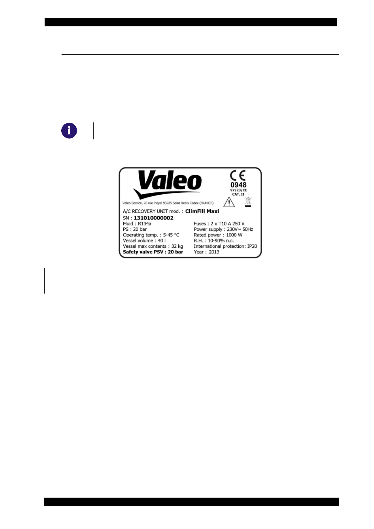
2.4 MARKING
The ClimFill® Maxi equipment has been manufactured in compliance with the European
Union directives listed in the Declaration of Conformity supplied with the pressure
equipment.
The equipment is a PED risk class III device (97/23/EC).
The characteristic data of the equipment are indicated on the specific data plate
applied onto the equipment side part.
It is prohibited to remove, damage or tamper with the equipment
NAMEPLATE
“data plate”.
Fac-Simile
CE MARKING: The present CE declaration is enclosed to the equipment. Store correctly
and provide on request.
ENGLISH 5 / 74 CAP. 2 - GENERAL INSTRUCTIONS

ClimFill Maxi
CAP. 3 -
SAFETY CONDITIONS
3.1 PERSONAL SAFETY INFORMATION
3.1.1 Definitions
DANGEROUS AREAS:
Any area within or close to the equipment implying risk for the safety and health of
exposed persons.
EXPOSED PERSON:
Any person completely or partially standing in a dangerous area.
OPERATOR:
The person/s charged with operating the machine for its intended purpose.
CLASSIFICATION OF OPERATORS
The operator can be classified according to two main categories, which, in some
cases, refer to one single person:
• The operator charged with the equipment operation has the duty to:
o Start up and monitor the machine's automatic cycle;
o Carry out simple setting operations;
o Remove the causes of equipment stop not implying breakings of
members but simple operating anomalies.
• Maintenance technician: a technician trained by an authorised VALEO SERVICE
centre, capable of working on the machine’s mechanical and electrical
components with its guards open to make adjustments and to service and repair
it.
USER
Body or person legally responsible for the equipment.
3.1.2 Personal safety information
The VALEO SERVICE ClimFill® Maxi A/C service station is particularly simple and reliable
due to its adjustments and functions. When used correctly it presents no hazard for the
operator, provided he observes the following general safety instructions and that the
service station is regularly serviced (incorrect maintenance/use compromise the
equipment's safety).
Before operating the service station for the first time, read these instructions carefully. If
any part of the instructions is unclear, contact your reseller or VALEO SERVICE. This
service station may be used by only one equipment operator, familiar with A/C and
refrigeration systems and the hazards associated with refrigerants and high pressure
equipment.
CAP. 3 - SAFETY CONDITIONS 6 / 74 ENGLISH
ClimFill Maxi
WORKPLACE: The equipment must be operated outdoor or in a well-ventilated location
(at least 1 air change per hour). The workshop has to be equipped with ventilation
systems able to ensure air change in every environment area or carry out a periodical
ventilation by opening the areas. Use the equipment away from heat sources or hot
surfaces . The equipment must not be used in explosion risk environments (potentially
explosive atmospheres). Before using it, put the equipment on a levelled plane and
secure position, blocking it with suitable wheel stops.
Do not expose the tool to direct sunrays, heat sources, rain and jets of water. Do not
smoke close to the equipment and during operations (keep at a distance of at least 1
m).
The work area must be monitored by the operator while the equipment is operating.
ATTENTION: the R134a refrigerant fumes/gases are heavier than air and can gather on
the floor or inside cavities/holes and cause choke by reducing the oxygen available for
breathing.
At high temperatures, the refrigerant breaks down releasing toxic and aggressive
substances, harmful for the operator and the environment.) Avoid inhaling the system
coolants and oils. Exposure can irritate eyes and the respiratory tract.
ELECTRICAL CONNECTION: Connect the power cord solely to a mains supply which
conforms with the ratings on the machine's nameplate (mounted on its side). Make sure
the mains socket is grounded.
Maximum impedance allowed in the point of connection to the mains shall comply
with standard EN 61000-3-11. Starting currents can cause short voltage drops, which
may affect other equipments under unfavourable conditions. If impedance in the point
of connection to the mains is not compliant, this may lead to interference so please
consult the electrical power network operator before connecting the equipment.
Never use the service station with a defective power cord or a different one from that
supplied with the machine. If damaged, immediately have it replaced with an original
spare part or equivalent by a VALEO SERVICE centre. Before opening the service
station, extract completely the supply cable from the plug, or you can get an electric
shock.
Do not tamper with or bypass the safety equipment and settings.
Do not leave the machine powered up when not in use; shut off the power supply
before leaving the equipment unused for a long time. Do not forget that the tool
(pressure tool) must always be protected.
ENGLISH 7 / 74 CAP. 3 - SAFETY CONDITIONS

ClimFill Maxi
REFRIGERANTS AND LUBRICANTS – PERSONAL PROTECTION EQUIPMENT AND
PRECAUTIONS: The refrigerants and the pressure vessels have to be handled with care,
otherwise there will be possible health risks.
The operator must wear safety glasses, gloves and protective clothing suitable to the
work. Contact with the refrigerant can cause blindness (eyes) and other physical
damage (freezing) to the operator. Avoid contact with the skin; the low boiling
temperature (about –26 °C for R134a) may cause burns.
Further information about safety can be obtained from the safety sheets of lubricant
and refrigerant producers.
Do not inhale refrigerant or oil vapour. Keep away from the vent valves and ventilation
coupling, especially when non-condensable gas is being vented.
Never direct the quick couplings (taps) towards your face or other persons or animals.
OTHER PROHIBITIONS AND USE LIMITATIONS: Use only pure R134a refrigerant, and do not
use it on vehicles containing other types of refrigerants. The mixture with other types of
refrigerant produces serious damage to the conditioning and cooling systems. Mixed
gases have to be disposed of according to current regulations. Do not use the ClimFill®
Maxi station with compressed air systems, R134a and air mixtures can be potentially
explosive.
Do not modify calibration of safety devices. Do not remove seals of safety valves and
of control systems. Do not use external tanks or other storage containers that are not
type-approved or without safety valves.
Make sure the equipment's aeration and ventilation ports are not obstructed or
covered while the equipment is operating.
CAP. 3 - SAFETY CONDITIONS 8 / 74 ENGLISH
ClimFill Maxi
HOSE CONNECTIONS: Hoses may contain pressurised refrigerant. Before changing the
service couplers, check the respective pressures in the hoses (pressure gauge).
Before connection to a car A/C system, to an external tank/vessel, check that the
quick couplers are closed (unscrewed HP and LP valves).
Scrupulously follow the instructions on the equipment's display.
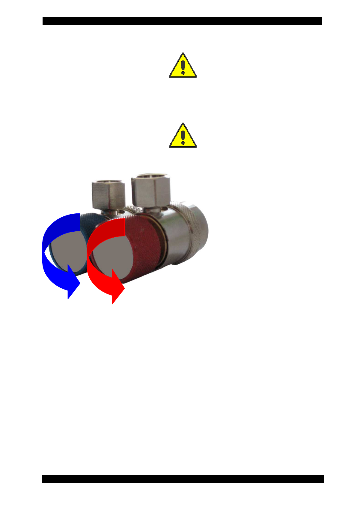
QUICK COUPLERS CLOSING/OPENING:
Opening (connect to the
vehicle):
clockwise
Closing (detach from the
vehicle):
counter clockwise
MAINTENANCE/GENERAL CLEANING: The equipment has to be serviced at the intervals
indicated by the equipment itself. These controls include also a leak self-test that the
equipment performs automatically.
The service station maintenance has to be performed according to the procedures
described in this manual and to the current safety regulations.
Use only VALEO SERVICE original parts.
When the equipment requires the dryer filter and the vacuum pump oil to be changed,
you have to be careful in the replacement.
A/C service station maintenance can be carried out exclusively by a trained operator
or by a service man of a VALEO SERVICE certified seller. If the maintenance is not
performed according to the expected schedule, the equipment will be blocked.
Do not use chemical agents for the service station cleaning, as they could attack the
material or the surface.
ENGLISH 9 / 74 CAP. 3 - SAFETY CONDITIONS
ClimFill Maxi
STOP FOR LONG PERIOD: Store the equipment in a safe place, disconnected from the
mains, away from excessive temperatures, humidity and the risk of damaging impact.
Contact the Technical Service to run a safety shutdown of the equipment, and if
scrapping the unit, to drain and recycle the R134a gas as required by local legislation.
To resume operation, repeat the installation (there is no need to register the unit anew
on the website) and run the commissioning trials and regular operational checks as
required by local legislation.
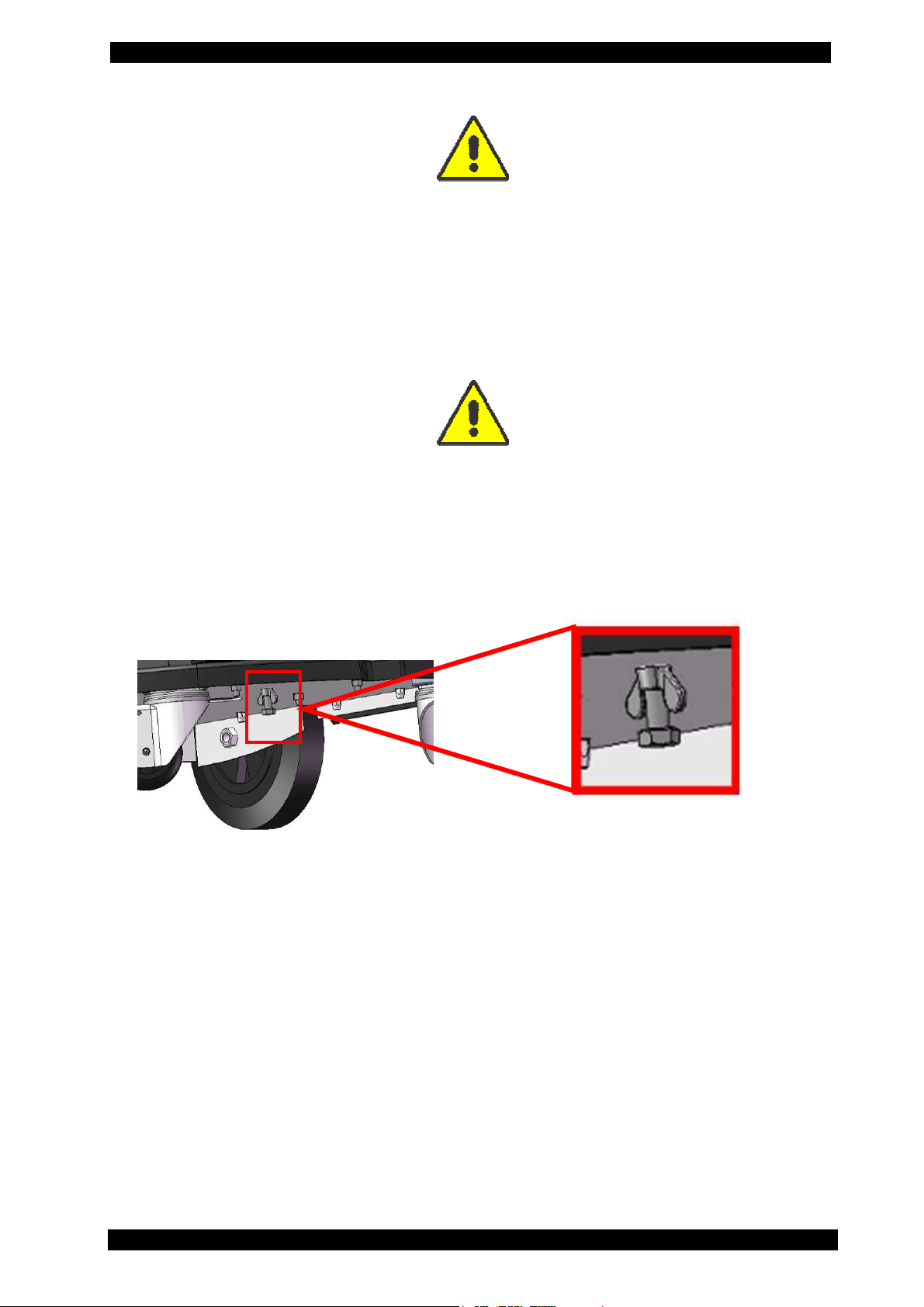
TRANSPORT: If the equipment has to be transported, you have to screw the safety screw
in order to fix the equipment scale. The safety device for transport is on the back of the
equipment and it consists of a bolt with wing-nut. Commissioning: Slacken the wing-nut,
unscrew the screw for about 4 mm. and fix it again with the wing-nut. Transport: slacken
the wing-nut, screw the screw by hand and then fix it again with the wing-nut. For the
transport of the R134a refrigerant, specific regulations are in force in every country.
Therefore, refer to your reseller or your authorised service centre for information.
CAP. 3 - SAFETY CONDITIONS 10 / 74 ENGLISH
ClimFill Maxi
3.2 IMPORTANT INFORMATION ON SERVICE EQUIPMENT
SAFETY
When using the equipment, the following operations are not allowed as they might
cause, under certain circumstances, danger for persons and cause permanent
damage to the equipment itself.
- Do not remove or make unreadable labels, signs and/or dangers signs
placed on the equipment and in the area nearby.
- Do not disable the unit's safety devices.
- Use only fuses identical to the originals as specified on the nameplate;
do not tamper with or attempt to repair the fuses.
If the power supply is known or can be expected to vary beyond the
limits specified for the service equipment, immediately disconnect it.
- The electrical system to which the service equipment is connected
must be configured as provided for by local legislation.
- Only operators or qualified staff instructed or certified for the
equipment maintenance can open the equipment. The equipment
contains parts which can cause electrocution: shut off power to the
equipment before servicing/repairing it.
3.3 SAFETY DEVICES
ClimFill® Maxi is equipped with the following safety devices:
SAFETY PRESSURE SWITCH: It stops the compressor in case of excessive
pressure.
SAFETY VALVE: The safety valve opens when the pressure inside the
Failure to observe any of the above safety instructions voids the equipment's warranty.
system reaches a level higher than the fixed limits.
MAIN SWITCH: Switches the equipment off by interrupting the power
supply. It is advisable to pull the power cord plug out of the mains
socket in any case before starting maintenance work.
ANY TAMPERING WITH THE ABOVE-MENTIONED SAFETY DEVICES IS
PROHIBITED.
ENGLISH 11 / 74 CAP. 3 - SAFETY CONDITIONS

ClimFill Maxi
CAP. 4 - LAYOUT AND USE OF THE MANUAL
4.1 USE OF THE MANUAL
• This manual shall accompany the equipment in case this is passed on to a new
user.
• The content of this manual has been drawn up in compliance with the guide
lines of the UNI standard 10893:2000.
• Diffusion, modification or use of this manual for own aims is forbidden.
• The manual uses symbols which call the reader's attention to specific points to
facilitate its use.
It includes all technical, operating, shutdown, maintenance, spare parts and safety
information.
• In case of doubts on the correct interpretation of the instructions, please contact
our technical service to obtain the required clarifications.
4.2 SYMBOLS
This paragraph describes the safety symbols which may be posted on the service
equipment.
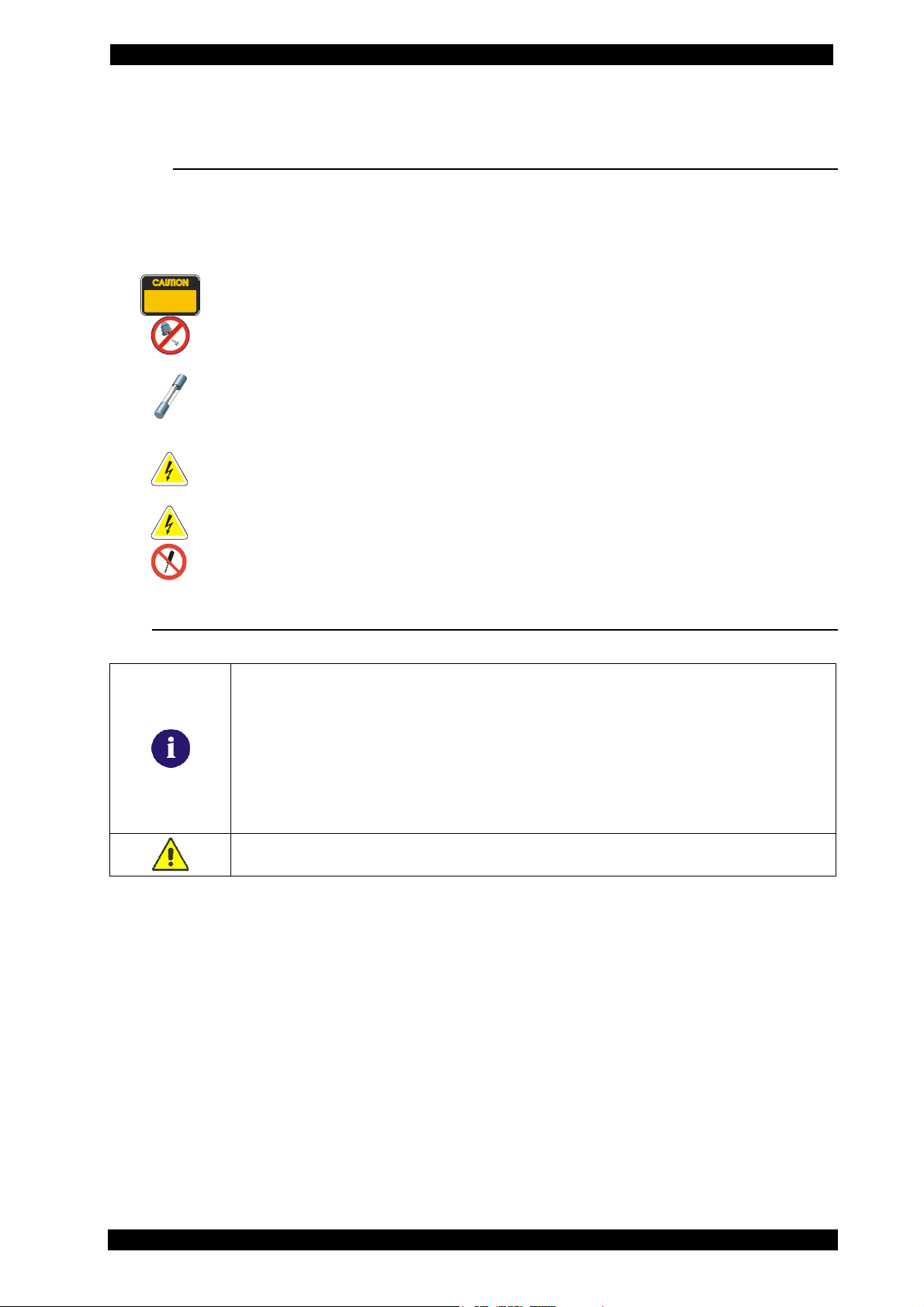
This manual is an integral part of the equipment and must be kept
near the equipment by the purchaser
Operations which are potentially hazardous for the operator are
highlighted with this symbol.
Such operations can cause serious injury.
Operations requiring special attention are highlighted with this symbol.
Such operations shall be carried out correctly to avoid causing
damage to objects or to the surrounding environment. This symbol also
highlights information to which special attention must be paid.
Operations which require careful reading of the manual's instructions
are highlighted with this symbol.
4.2.1 Safety
ALTERNATING CURRENT
CONSULT THE INSTRUCTIONS MANUAL
SAFETY GROUNDING
ATTENTION! ELECTROCUTION HAZARD
CAUTION !: DO NOT REMOVE THE COVER
(maintenance technicians only)
USE PROTECTIVE GLOVES
WEAR PROTECTIVE GOGGLES
USE ANTI-SMASH SAFETY SHOES
CAP. 4 - LAYOUT AND USE OF THE MANUAL 12 / 74
ENGLISH

ClimFill Maxi
4.3 GLOSSARY
To make the reading of this manual easier, we have prepared the list of the most
important technical terms used in the manual.
Refrigerant: Refrigerant fluid used in advanced motor vehicle A/C systems.
The following refrigerant fluids may be used:
o R-134a C2H2F4 - 1,1,1,2-Tetrafluoroethane
A/C system: air conditioning system.
Equipment: ClimFill® Maxi service station for recovering, recycling, draining and
charging the A/C system.
External tank: Refrigerant bottle used to fill the internal vessel.
Internal vessel: vessel for refrigerant storage.
Phase: Performance of a single function.
Cycle: Sequence of steps.
Recovery: Extraction of refrigerant from the vehicle.
Recycling: Cleaning of refrigerant, includes: separating out oils, removal of non-
condensable gas and single/multiple pass through filters to reduce the humidity,
acidity and particulate content of the fluid.
Disposal: disposal of refrigerant for storage followed by destruction/scrapping by an
authorised waste management centre.
Vacuum cycle: Draining out of a motor vehicle A/C system and separation out of
condensed matter and humidity, using only the vacuum pump.
Oil injection: Injection of oil into an A/C system to ensure the correct charge as
specified by the vehicle's manufacturer.
Charge: filling of refrigerant into the A/C system in the amount specified by the
manufacturer.
System flushing: Cleaning phase for the removal of possible polluting substances from
the A/C system or parts of it.
Non condensable gases: Gas stored in the gaseous phase, including air and nitrogen.
ENGLISH 13 / 74 CAP. 4 - LAYOUT AND USE OF THE MANUAL
ClimFill Maxi
4.4 GUIDELINES FOR HANDLING REFRIGERANT
4.4.1 Precautions for refrigerant storage
The refrigerant removed from the A/C system must be handled with care to prevent or
minimise the risk of mixing with other refrigerants.
This equipment is designed to handle refrigerant R134a.
The external vessels used to store the refrigerants must be clearly marked to prevent
mixing different refrigerants.
The vessels must be free of oil and other contaminants.
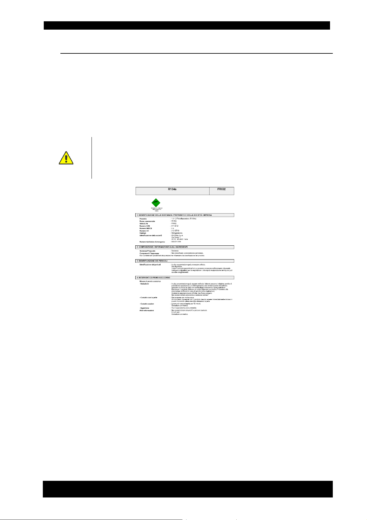
ATTENTION: when handling, using and storing R-134a gas and dealing
with emergency situations, MAKE SURE to refer to the product's safety
sheet.
GET THE SAFETY SHEET FROM YOUR REFRIGERANT SUPPLIER AND FOLLOW
ITS INSTRUCTIONS
Fac-Simile
4.4.2 Refrigerant conditions
The condition of the refrigerant is critical to the operation of the vehicle's A/C system.
Running repairs properly following failure or damage ensures the quality of the
refrigerant itself (particulates, acids and water).
4.4.3 Recycling capacity
The service equipment's filtering systems must be replaced regularly (see maintenance
messages) to ensure effective recycling.
CAP. 4 - LAYOUT AND USE OF THE MANUAL 14 / 74
ENGLISH
ClimFill Maxi
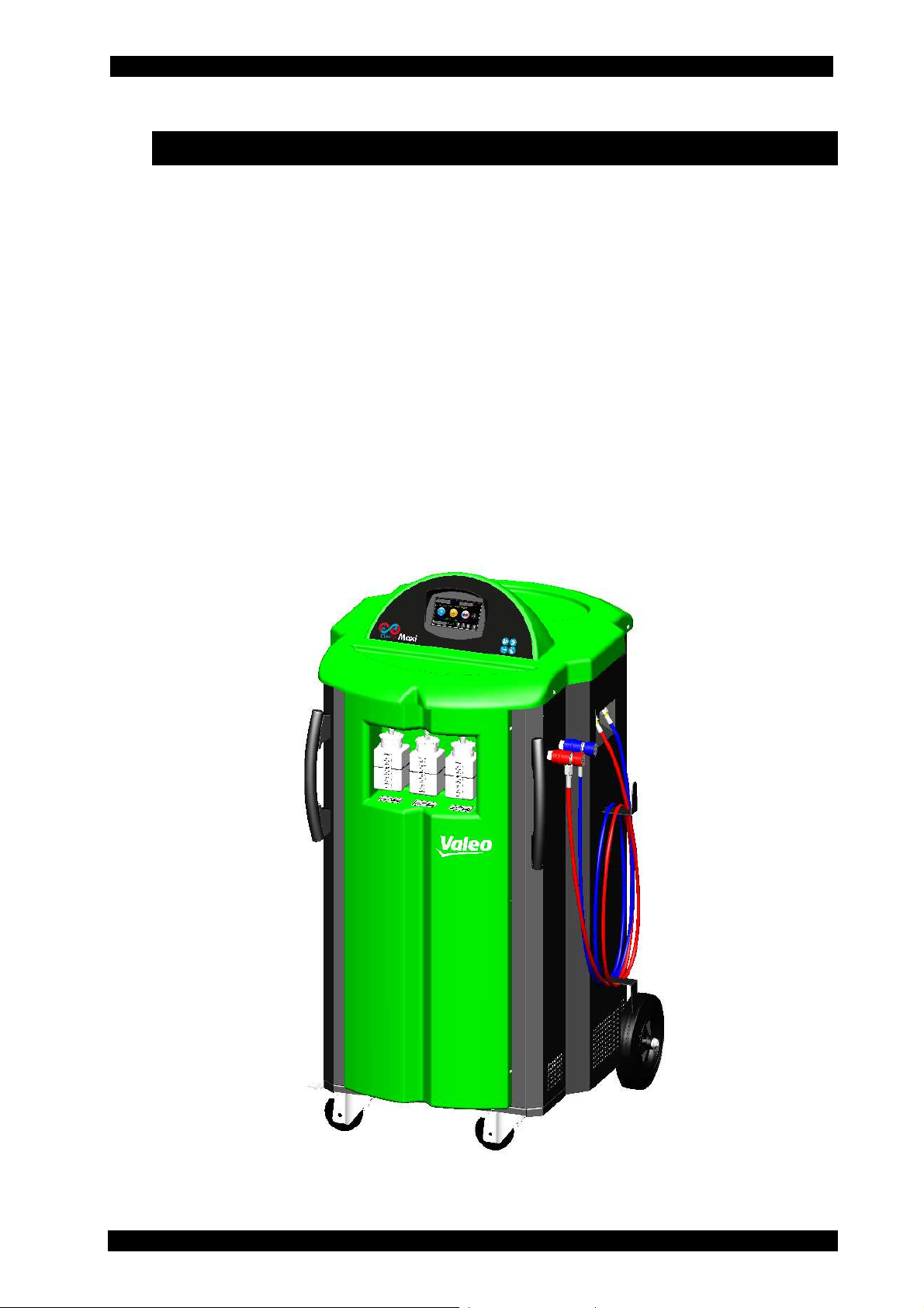
CAP. 5 - GENERAL DESCRIPTION
The advanced technology and innovative concept employed in designing and
fabricating ClimFill® Maxi makes it extremely simple and reliable in operation.
With its vessel holding up to 32 kg of refrigerant, ClimFill® Maxi has been specifically
designed for the maintenance and service of vehicle A/C systems containing large
amounts of refrigerant, particularly buses.
However, it can also be used to recharge vehicles with smaller amounts, such as cars.
ClimFill® Maxi is assembled by the manufacturer according to established EU standards
and undergoes service trials on completion.
The ClimFill® Maxi as recharge methods uses two modes, the Q-Mode (Quick Mode) or
S-Mode (Suction Mode).
The Q-Mode for this model ClimFill® Maxi is based on the patented technology
Supercharge which allows for increasing the refrigerant injection speed by charging
an A/C loop from the HP side while recovering, at the same time, from LP (if available).
The S-Mode (Suction Mode) assure to complete the refrigerant recharge, but needs
always to turn on the vehicle engine and the A/C system to recharge refrigerant from
LP side.
ENGLISH 15 / 74 CAP. 5 - GENERAL DESCRIPTION
ClimFill Maxi
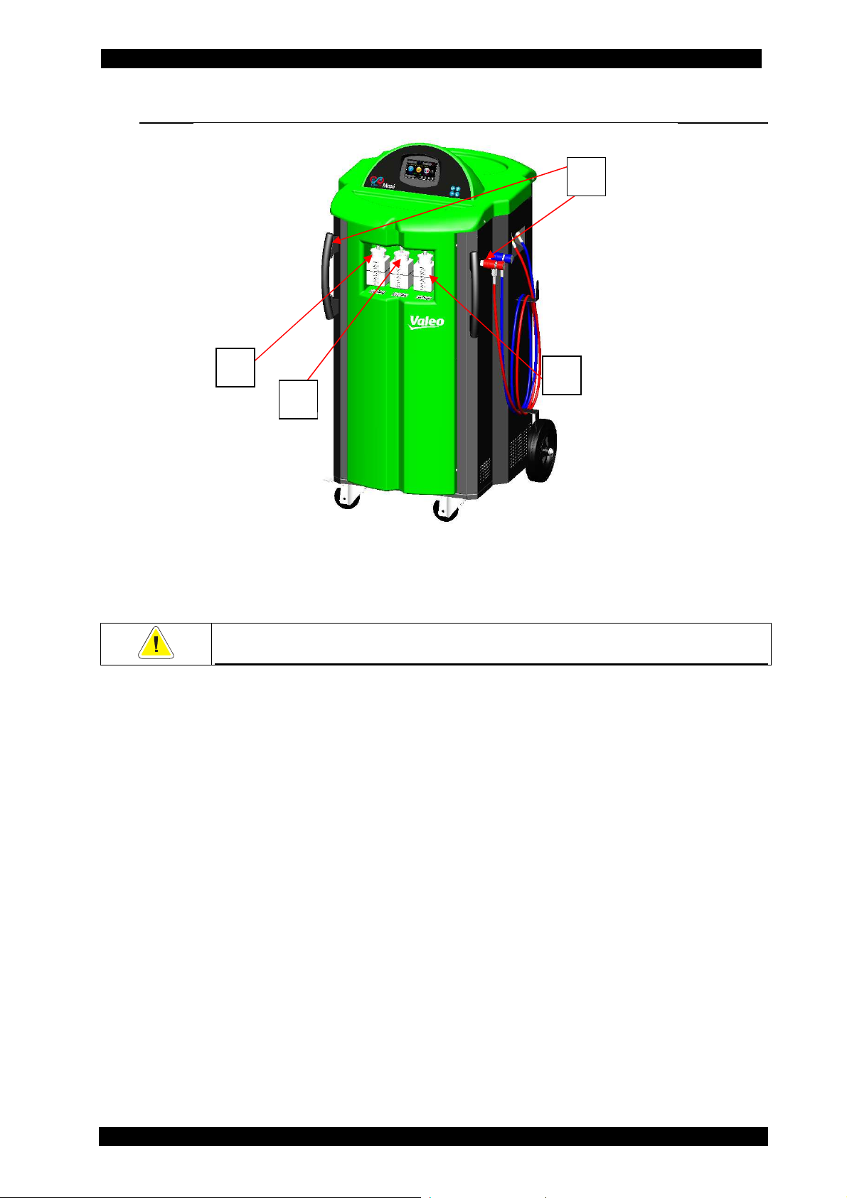
5.1 FRONT VIEW (EXTERIOR)
4
1
2
1. New PAG oil container 250 cc
2. Exhausted oil container 250 cc
3. UV contrast fluid container 250 cc
4. Handles
ONLY MAINTENANCE TECHNICIANS MAY REMOVE THE FRONT AND REAR
DOORS OR THE TOP COVER
3
CAP. 5 - GENERAL DESCRIPTION 16 / 74 ENGLISH
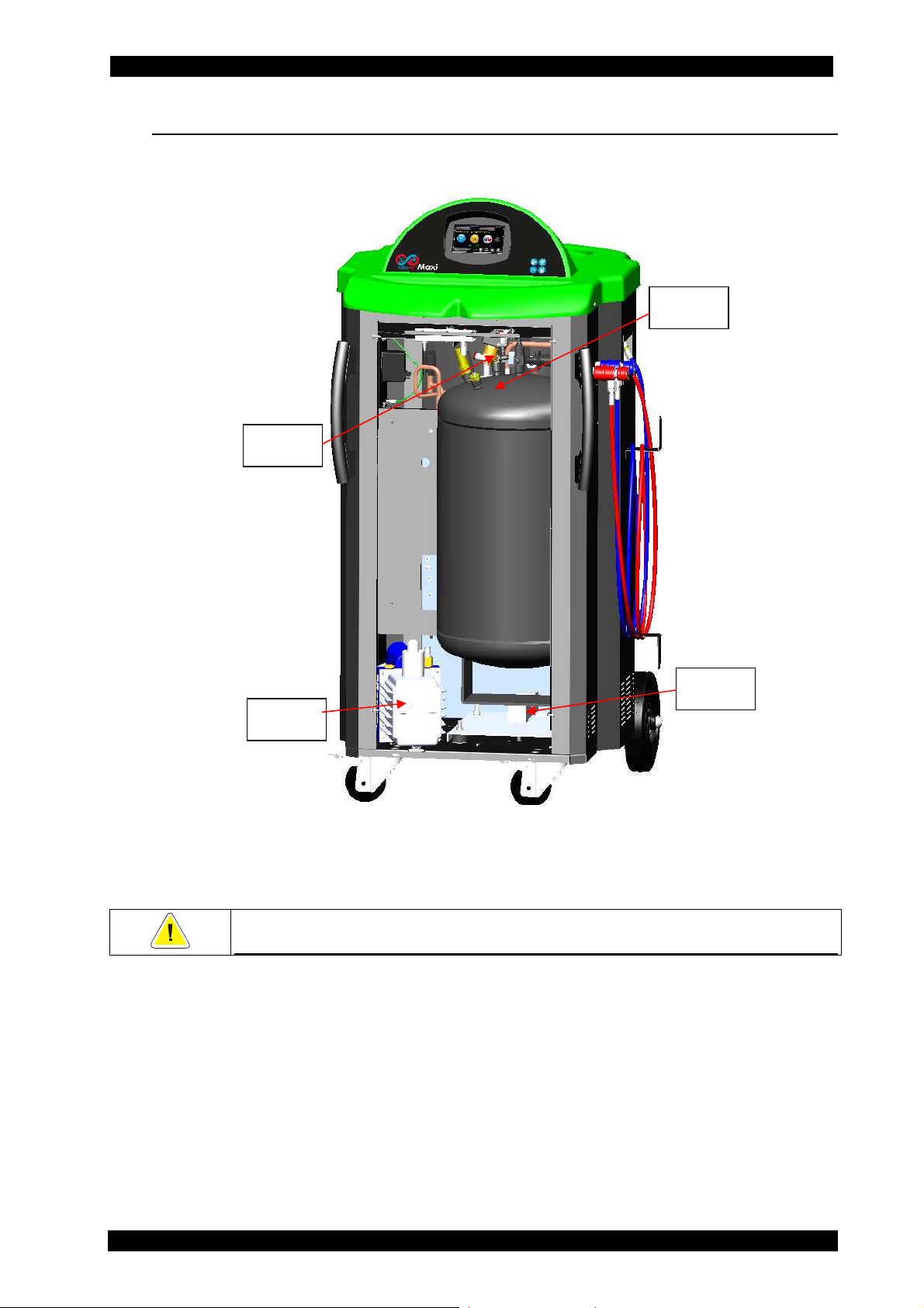
5.2 FRONT VIEW (INTERIOR)
8
ClimFill Maxi
6
5
5. Vacuum pump
6. Refrigerant tank 40 L
7. Load cell
8. Non-condensable gas vent valve (automatic)
ONLY MAINTENANCE TECHNICIANS MAY REMOVE THE FRONT AND REAR
DOORS OR THE TOP COVER
7
ENGLISH 17 / 74 CAP. 5 - GENERAL DESCRIPTION
ClimFill Maxi
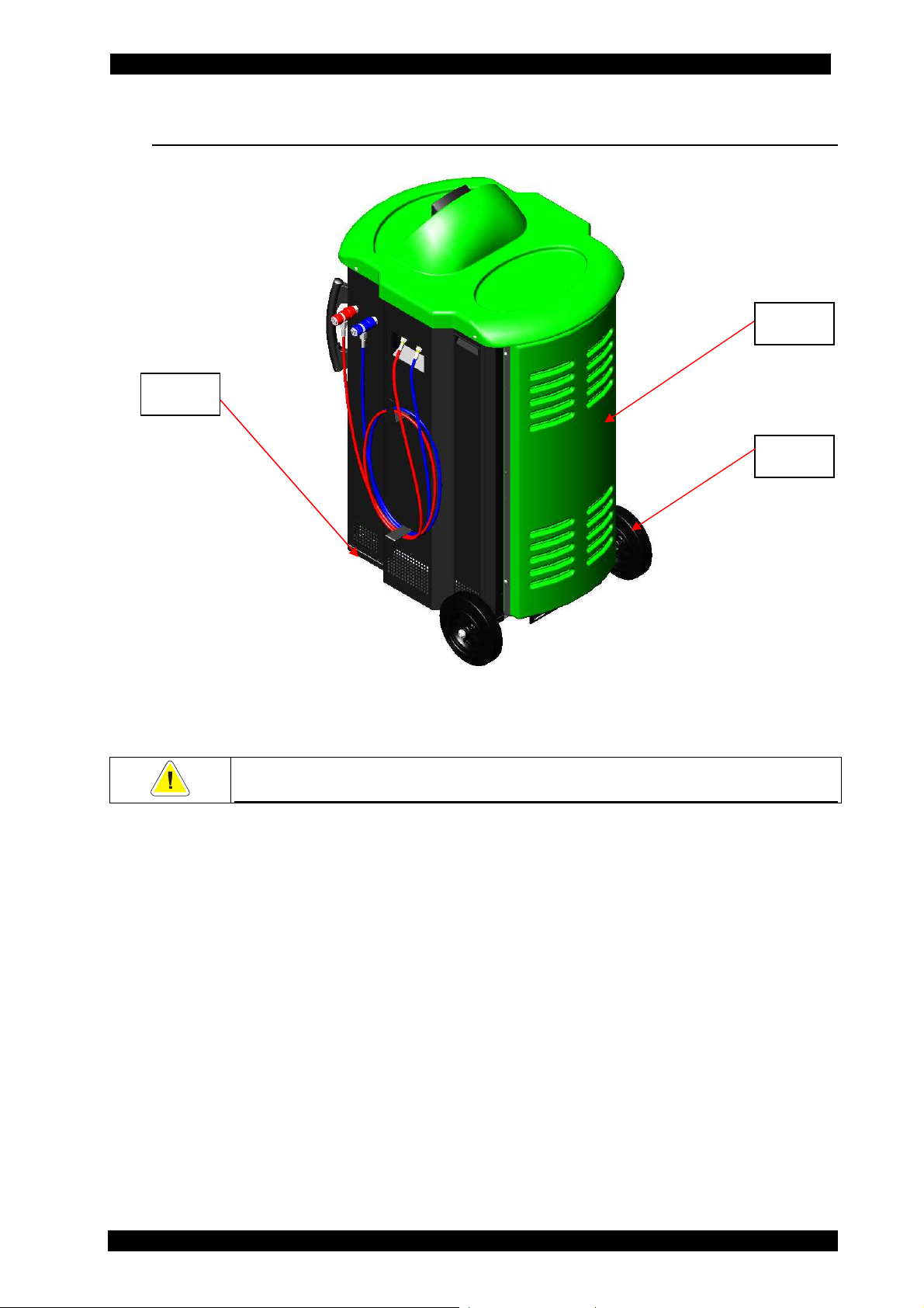
5.3 REAR VIEW (EXTERIOR)
9
11
10
9. Caster wheels, with brakes
10. Handling wheels
11. Rear door
ONLY MAINTENANCE TECHNICIANS MAY REMOVE THE FRONT AND REAR
DOORS OR THE TOP COVER
CAP. 5 - GENERAL DESCRIPTION 18 / 74 ENGLISH
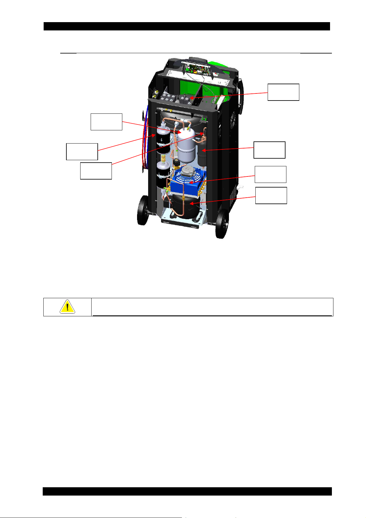
5.4 REAR VIEW (INTERIOR)
13
ClimFill Maxi
12
14
15
12. Manifold
13. Distiller
14. Dryer filter
15. Safety pressure switch
16. Oil separator
17. Vented condenser
18. Compressor
ONLY MAINTENANCE TECHNICIANS MAY REMOVE THE FRONT AND REAR
DOORS OR THE TOP COVER
16
17
18
ENGLISH 19 / 74 CAP. 5 - GENERAL DESCRIPTION

ClimFill Maxi
5.5 RIGHT SIDE VIEW
19
20
19. HP hose and quick coupling
20. LP hose and quick coupling
DO NOT USE THE UNIT UNLESS THE CHARGING HOSES (HP – LP) ARE
CAP. 5 - GENERAL DESCRIPTION 20 / 74 ENGLISH
CORRECTLY CONNECTED
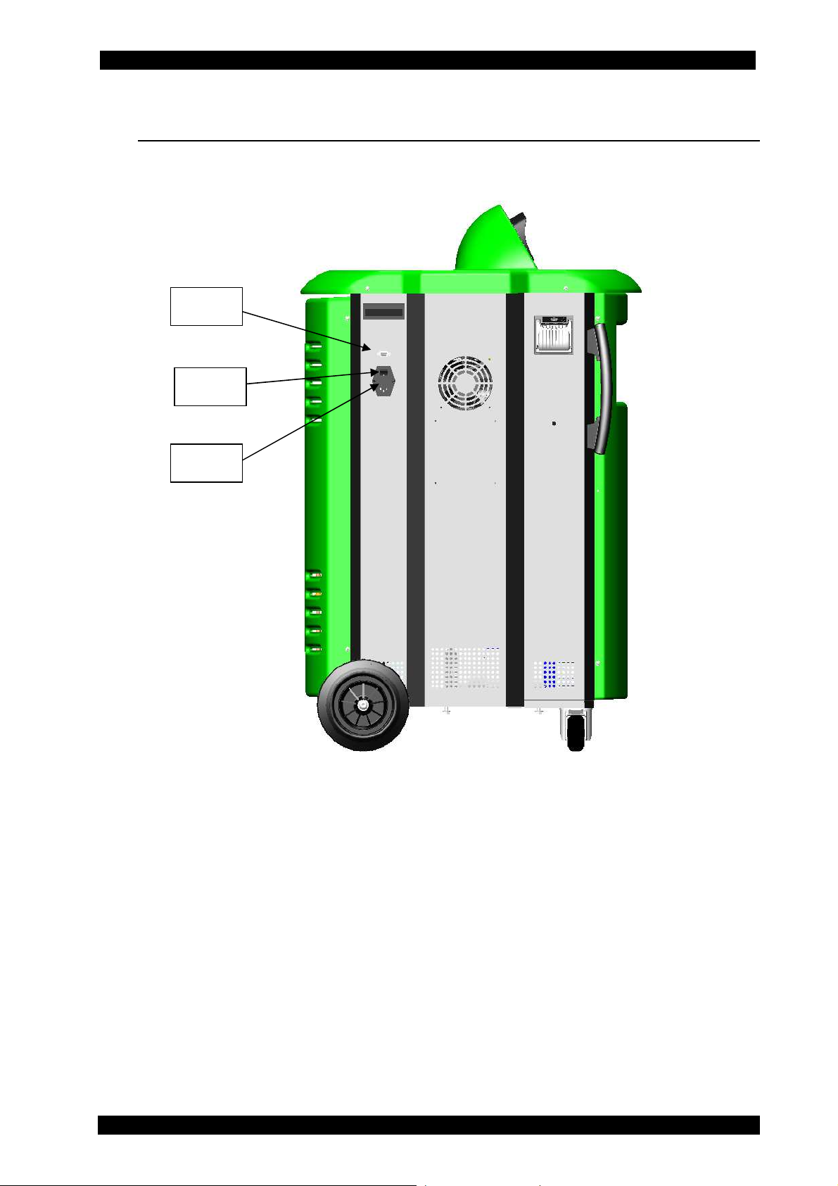
5.6 LEFT SIDE VIEW
21
22
23
ClimFill Maxi
21. RS232 serial port (updating software installation interface)
22. Main switch
23. 230 VAC MAINS SUPPLY FUSES (5x20 T 10A 250V)
ENGLISH 21 / 74 CAP. 5 - GENERAL DESCRIPTION
ClimFill Maxi
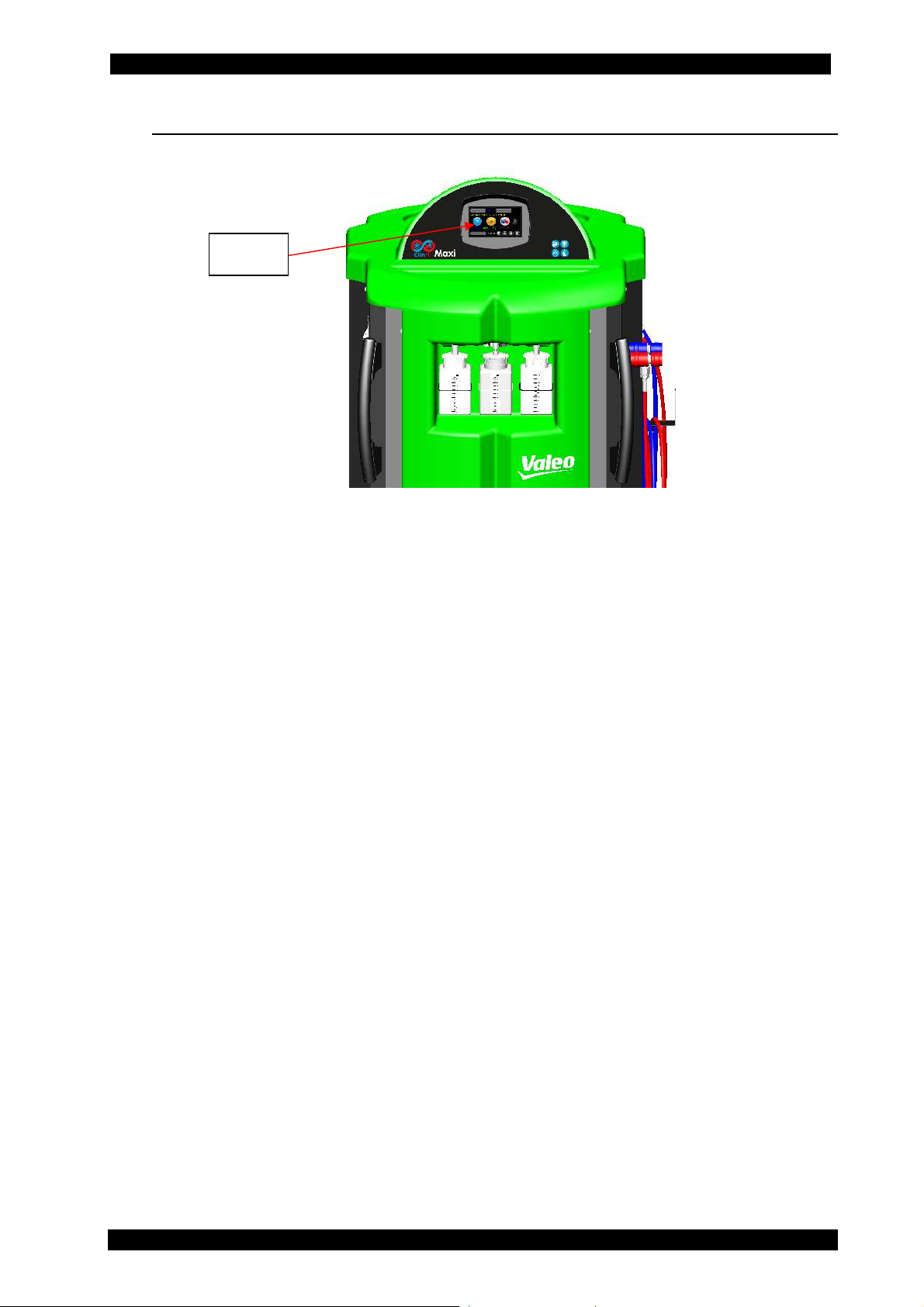
5.7 FRONT SIDE VIEW
24
24. Touch Screen graphic display
CAP. 5 - GENERAL DESCRIPTION 22 / 74 ENGLISH
ClimFill Maxi
5.8 TOUCHSCREEN
All settings, controls and service functions are available on the touchscreen display. It
also displays the service equipment’s status, the progress of A/C system service and any
alarms and error messages.
The touchscreen is the basic operator interface and can be operated with the fingers
or some other object, such as a pen.
When a button is pressed, a beep sounds.
The following functions are available:
scroll left: previous menu
scroll up: top menu
scroll down: lower menu
press: confirm / enter
press and hold: open the function to change it or press the ''home'' button
double press: supplementary functions
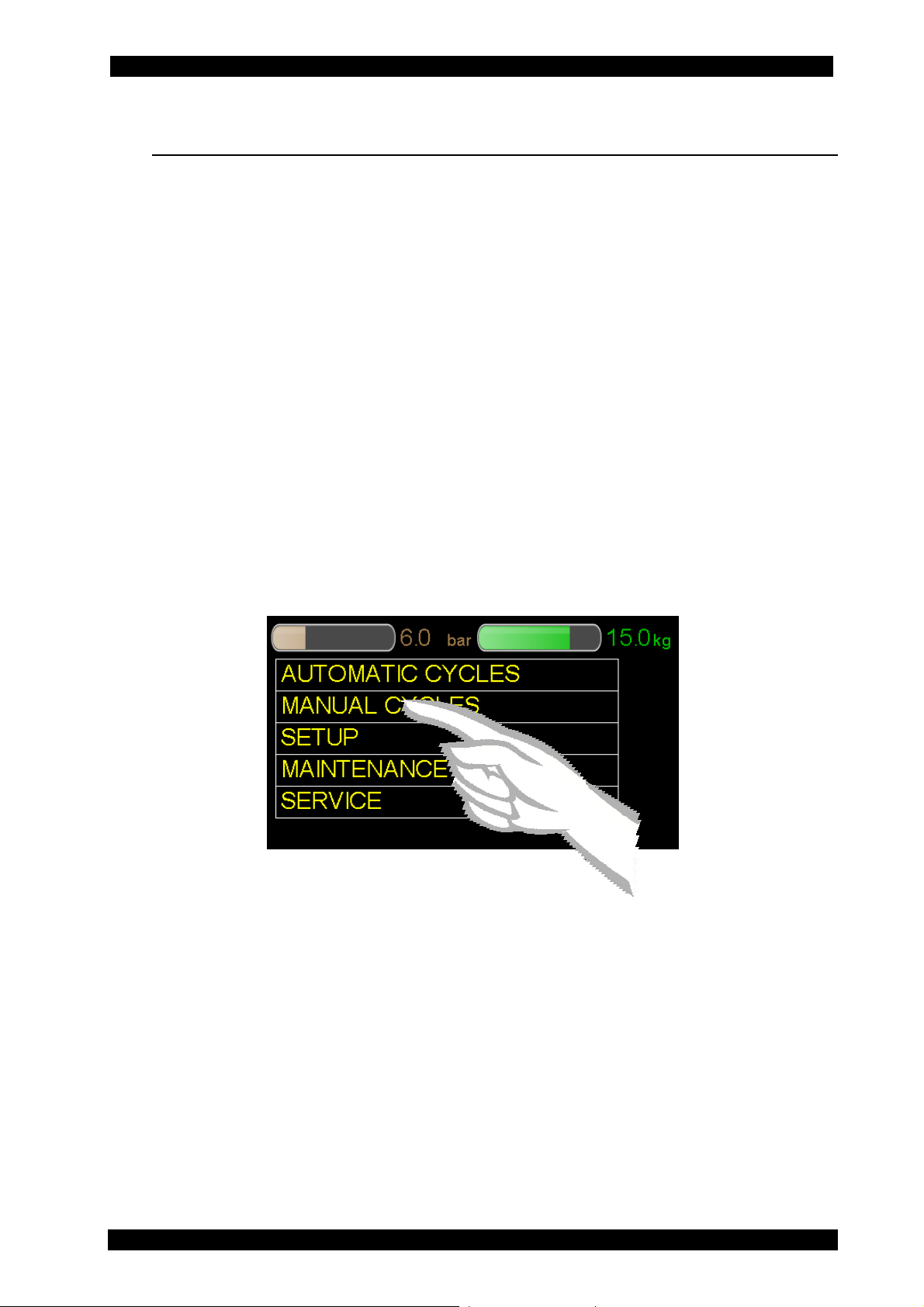
To select a MENU (e.g. MANUAL CYCLES), press the text MANUAL CYCLES: the selection
occurs when the finger is released, the selected entry is pointed out with a different
colour and the menu screen page changes.
If there are descriptions that need more space on the screen page, for example the
manual cycles list (see the screen page below), or in case of setup, it is possible to
display the different entries by moving the scroll bar to the side. For this reason, it is
necessary to touch the grey point on the scroll bar and slide up or down with the finger.
Lift the finger when you are on the desired position.
By touching the scroll bar once, the menu moves one line up or down depending on
whether it is touched over or under the grey dot.
The “home” icon is the button to “interrupt/return to the main menu’’.
To access to the main menu you have to touch it for 2 seconds. Sliding to the left with
the finger you can access to the previous menu.
ENGLISH 23 / 74 CAP. 5 - GENERAL DESCRIPTION
 Loading...