


632202 • INSTRUCTION MANUAL
FR MANUEL D’INSTRUCTION
NL INSTRUCTIEHANDLEIDING
ES MANUAL DE INSTRUCCIONES IT MANUALE DI ISTRUZIONI DE GEBRAUCHSANWEISUNG
CS NÁVOD K POUŽITÍ PL INSTRUKCJA OBSŁUGI
HU HASZNÁLATI ÚTMUTATÓ
INNOVATION
FOR EVERYONE

EN
beep&park® Parking assistance system
Instruction manual
Thank you for purchasing this product. Please read the manual
carefully before commencing installation and using the unit.
FR
ES
DE
NL
CS
PL
beep&park® Système d’aide au stationnement
Notice d’utilisation
beep&park® Asistente de aparcamiento
Manual de instrucciones
IT
beep&park® Sistema di assistenza al parcheggio
Istruzioni d’uso
beep&park® Einparkhilfe
Bedienungsanleitung
beep&park® Parkeerhulpsysteem
Montagehandleiding
beep&park® Parkovací asistenční systém
Návod k použití
beep&park® Asystent parkowania
Instrukcja obsługi
Merci d’avoir acheté ce produit. Lire attentivement
la notice avant d’installer et d’utiliser l’appareil.
Gracias por comprar este producto. Por favor, antes de comenzar
la instalación y utilización lea atentamente el manual de instrucciones.
Grazie di aver acquistato questo prodotto. Leggere attentamente
le istruzioni prima di installare e utilizzare il prodotto.
Vielen Dank, dass Sie sich für dieses Produkt entschieden haben. Lesen
Sie die Bedienungsanleitung sorgfältig bevor Sie das Produkt benutzen.
Hartelijk dank voor de aanschaf van dit product. Lees de handleiding goed
door voordat u met het inbouwen begint en het systeem gaat gebruiken.
Děkujeme za zakoupení tohoto produktu. Před zahájením instalace
a používání pečlivě přečtěte příručku.
Dziękujemy za zakup tego produktu. Prosimy o uważne przeczytanie niniejszej
instrukcji przed rozpoczęciem instalacji i użytkowania urządzenia.
HU
beep&park® Parkolást segítő rendszer
Használati útmutató
Köszönjük, hogy termékünket választotta. Kérjük, a termék beszerelése
és használata előtt olvassa el gyelmesen ezt az útmutatót.

FR ESEN
Table of contents
Introduction & Feature .................................................... 7
Caution ......................................................................................11
Box contents ........................................................................15
Tools needed ........................................................................17
Installation..............................................................................19
1- Set up sensors on bumper (F/R) .................................19
2- Choose the correct angle ring .....................................23
3- Set up the jumper on ECU............................................... 29
4- Connect the ECU (front/rear) .......................................31
5- Set up Display (front/rear) ..............................................35
6- Functional test ........................................................................ 37
7- False detection may occur in such cases ............39
8- Self diagnosis ...........................................................................41
9- Troubleshooting .....................................................................43
Optional installation ........................................................49
1- Set up the radio mute function ..................................49
2- Tow bar .........................................................................................53
3- Install the manual desactivation ...............................55
4- Instructions for painting the sensors ....................57
Technical parameters .....................................................59
Wiring diagram .....................................................................63
Sommaire
Introduction & Caractéristiques ................................ 7
Mise en garde .......................................................................11
Contenu du pack ................................................................15
Outils nécessaires .............................................................17
Installation..............................................................................19
1-Installer les capteurs dans le pare-choc (AV-ARR) ..19
2-Choisir la bonne bague correctrice d’angle ..........23
3-Positionner les jumper sur l’Unité de Contrôle
Electronique (UCE) ................................................................ 29
4- Installer l’UCE ............................................................................31
5- Installer l’écran (AV-ARR) ............................................... 35
6- Tests fonctionnels................................................................ 37
7- Risque d’erreur de détection dans les cas suivants ..39
8- Auto-diagnostisque ............................................................41
9- Dépannage ................................................................................ 43
Installation optionnelle .................................................49
1- Désactiver la radio pendant le recul ........................49
2- Attache remorque .................................................................53
3- Installer un bouton de désactivation du système ..55
4- Instructions pour peindre les capteurs .................57
Paramètres techniques .................................................59
Diagramme de connection .........................................63
Tabla de contenidos
Instrucciones & Características ................................. 7
Precaución ..............................................................................11
Contenido de la caja ..................................................................15
Herramientas necesarias .............................................17
Instalación ..............................................................................19
1-Conguración de sensores en parachoques ...... 19
2- Elija el anillo angular correcto .......................................23
3- Conguración del parachoques en la UEC ..........29
4- Conexión de la UEC ..............................................................31
5- Conguración del la pantalla .........................................35
6- Tests de funcionalidad ......................................................37
7- Puede darse una falsa alarma en estos casos ....39
8- Autodiagnóstico .....................................................................41
9- Solución de problemas ...................................................... 43
Instalación opcional. ........................................................49
1-Congurar la función de silencio en la radio .......49
2- Barra de remolque .................................................................53
3- Instalar la desactivación manual ................................ 55
4- Instrucciones para pintar los sensores ................57
Parámetros técnicos .......................................................59
Diagrama de cableado ...................................................63
3

IT DE NL
Sommario Inhaltsangabe Inhoudsopgave
Introduzione & Caratteristiche ................................... 7
Avvertenze .............................................................................11
Contenuto della scatola .........................................................15
Attrezzi necessari .............................................................17
Installazione ..........................................................................19
1- Posizionamento dei sensori sul paraurti .............. 19
2- Scegliere l’anello corretto ................................................23
3- Inserimento del ponte nella centralina ECU ...... 29
4- Connessione della centralina ECU ............................31
5- Posizionamento del display ...........................................35
6- Test di funzionamento ...................................................... 37
7- In questi casi può vericarsi un falso
rilevamento dell’ostacolo ................................................. 39
8- Auto diagnosi ........................................................................... 41
9- Risoluzione dei problemi .................................................. 43
Installazioni opzionali .....................................................49
1- Congurazione della funzione muto per l’autoradio ....49
2- Barre di traino ...........................................................................53
3- Installazione della disattivazione manuale ........55
4- Istruzioni per verniciare i sensori ...............................57
Parametri tecnici ................................................................59
Schema elettrico ................................................................63
Einleitung & Funktionen ................................................. 7
Vorsicht .....................................................................................11
Verpackungsinhalt ......................................................................15
Benötigtes Werkzeug ....................................................17
Einbau ........................................................................................19
1- Einrichtung der Sensoren am Stoßfänger .......... 19
2- Wählen Sie den korekten Winkeleinstellring .....23
3- Einstellung des Modus (Front- oder
Heckmodus am Steuergerät ........................................29
4- Verbindung des Steuergeräts ......................................31
5- Einstellen der Anzeige .......................................................35
6- Funktionstest ...........................................................................37
7-In diesen Fällen können Fehlmessungen erfolgen ....39
8- Selbstdiagnose ....................................................................... 41
9- Fehlerbehebung ..................................................................... 43
Optionale Installation .....................................................49
1- Einrichten der Radiostummschaltung ...................49
2- Anhängerkupplung............................................................... 53
3- Manuelle Deaktivierung des Systems....................55
4- Anleitung zum Lackieren der Sensoren ................57
Technische Parameter ...................................................59
Schaltplan ...............................................................................63
Inleiding en kenmerken ....................................................7
Waarschuwing .....................................................................11
Inhoud verpakking ............................................................15
Benodigd gereedschap .................................................17
Montage-instructies .......................................................19
1- Montage sensoren in bumper ......................................19
2- Kies de juiste stelring .........................................................23
3- Jumper correct instellen op ECU .................................29
4- Aansluiten ECU ...................................................................... 31
5- Montage display ..................................................................... 35
6- Test systeem ............................................................................ 37
7- Onjuiste detectie kan voorkomen in deze gevallen ......39
8- Zelfdiagnose .............................................................................41
9- Storingzoeken ..........................................................................43
Installatie opties ................................................................49
1- Congureren mute-functie autoradio ...................49
2- Trekhaak .......................................................................................53
3- Montage handbediende uitschakeling ..................55
4- Spuitinstructies sensoren ............................................... 57
Technische gegevens ....................................................59
Bedradingsschema ...........................................................63
4

PL HUCS
Obsah Spis treści Tartalomjegyzék
Úvod & funkce ........................................................................7
Varování ....................................................................................11
Obsah balení..........................................................................15
Potřebné nářadí ..................................................................17
Instalace ...................................................................................19
1- Nastavení snímače v nárazníku ..................................19
2- Výběr vhodné podložky pro nastavení úhlu.......23
3- Nastavení spojení s elektronickou řídící jednotkou (ECU) ...29
4- Připojení ECU ............................................................................ 31
5- Nastavení displeje .................................................................35
6- Test funkcí .................................................................................. 37
7- K chybné detekci může dojít v těchto případech ......39
8- Samodiagnostika ................................................................... 41
9- Odtraňování problémů .......................................................43
Volitelná instalace ............................................................49
1- Nastavení funkce ztlumení rádia ...............................49
2- Tažným zařízením ................................................................ 53
3- Instalace ruční deaktivace ............................................. 55
4- Instrukce pro lakování senzorů .................................... 57
Technické parametry.......................................................59
Schéma elektrického zapojení .................................63
Wprowadzenie i funkcje .................................................. 7
Uwaga .......................................................................................11
Zawartość opakowania. ...............................................15
Niezbędne narzędzia ......................................................17
Instalacja ..................................................................................19
1- Zainstaluj czujniki na zderzaku....................................19
2- Wybierz odpowiednią podkładkę kątową............. 23
3- Zamontuj zworkę w centralce sterującej
(ECU) w zależności od trybu użytkowania .........29
4- Podłącz ECU .............................................................................. 31
5- Podłącz wyświetlacz .......................................................... 35
6- Test działania ...........................................................................37
7- Nieprawidłowa detekcja może wystąpić
w następujących przypadkach ....................................39
8- Autodiagnostyka ...................................................................41
9- Rozwiązywanie problemów...........................................43
Opcjonalna instalacja......................................................49
1- Ustawienie funkcji wyciszania radia .......................49
2- Hak holowniczy ....................................................................... 53
3- Ustawianie funkcji manualnego wyłączania .... 55
4- Instrukcja lakierowania czujników .............................57
Parametry techniczne ....................................................59
Schemat instalacji elektrycznej ..............................63
Bevezetés & működési jellemzők ............................. 7
Figyelmeztetés ...................................................................11
Csomag tartalma ...............................................................15
Szükséges szerszámok .................................................17
Installáció ................................................................................19
1- Szenzorok beállítása a lökhárítón .............................19
2- Válasszuk ki a helyes dőlésszög beállító gyűrűt ...23
3- Állítsuk be a váltóvezetéket (jumpert)
az elektronikus vezérlő egységen (ECU) ............29
4- Csatlakoztassuk az ECU-t ...............................................31
5- Állítsuk be a kijelzőn ............................................................ 35
6- Funkció teszt ............................................................................37
7- Hibás érzékelés előfordulhat az alábbi esetekben ...39
8- Öndiagnosztika ....................................................................... 41
9- Hibaelhárítás .............................................................................43
Opcionális beállítások ....................................................49
1- Állítsa be a rádión a némítás funkciót....................49
2- Vonóhoroggal...........................................................................53
3- Installáljuk a manuális hatástalanítást ..................55
4- Tájékoztató az érzékelők festéséhez .....................57
Műszaki jellemzők .............................................................59
Kábelezési séma ................................................................63
5

6
EN
Features
FR
Fonctionnalités
ES
Características
IT
Funzionalità
H
G
F
E
DE
Funktionen
NL
Kenmerken
CS
Funkční vlastnosti
PL
Funkcje
HU
A rendszer
működéséről röviden
D
C
B
A
7

EN FR ES
Assisting the driver during the parking
maneuvers alerting the driver of detected
obstacles with an audible warning.
System can be tted either for rear mode
detection or for front mode detection.
Features
• Suitable for vehicle length of maximum 5m
(for longer vehicle, 6m extra wire available
as spare part)
• Display with adjustable volume
• Compatible with pulsed rear light signal.
REAR MODE additional Features
• The system is compatible with tow bar
tted on vehicles.
• Activation by engaging the reverse gear
• Possible to set up the system to mute
the auto radio (see optional installation)
FRONT MODE additional Features
• The system is compatible with bull bar tted
on vehicles.
• Activation by pressing the brake pedal or
engaging the reverse gear (remain activated
between 8-20s when the brake pedal is
released - see installation)
8
Détecte les obstacles en informant les
conducteurs lors de manœuvres par un signal
sonore.
Ce système peut être installé aussi bien sur
un pare-choc arrière que sur un pare-choc avant.
Fonctionnalités
• Montable sur des véhicule d’une longueur
maximale de 5m (pour les véhicules plus
long, un câble additionnel de 6m de long
est disponible en pièce détachée)
• Ecran avec volume sonore ajustable
• Compatible avec la marche arrière pulsée
Caractéristiques additionnelles
pour le MONTAGE ARRIÈRE
• Le système est compatible avec une attache
remorque montée sur le véhicule
• Activation en passant la marche arrière
• Possibilité d’activer le système pour mettre
la radio en sourdine (voir installation optionnelle)
Caractéristiques additionnelles
pour le MONTAGE AVANT
• Le système est compatible avec un
pare-buemonté sur le véhicule
• Activation en appuyant sur la pédale de
frein ou en passant la marche arrière (reste
activé entre 8 et 20 secondes une fois la
pédale de frein relachée- voir installation)
Ayuda al conductor durante las maniobras de
estacionamiento alertando de los obstáculos
detectados con una advertencia audible.
El sistema puede ser instalado tanto para la
detección del modo posterior como para la
detección del modo frontal.
Características
• Válido para vehículos de una longitud máxima
de 5m (para un vehículo más largo, 6m de
cable extra disponible como pieza de repuesto)
• Pantalla con volumen ajustable
• Compatible con señal de luz trasera pulsada.
Características adicionales
del MODO TRASERO
• El sistema es compatible con la barra de
remolque instalada en los vehículos.
• Activación mediante la conexión de la
marcha atrás
• Posibilidad de congurar el sistema para
silenciar la radio automática (consulte la
instalación opcional).
Características adicionales
del MODO FRONTAL
• El sistema es compatible con defensas
montadas en los vehículos.
• Activación presionando el pedal del freno
o accionando la marcha atrás (permanece
activada entre 8-20s cuando se suelta el
pedal del freno - vea la instalación).

IT DE NL
Assiste il guidatore durante le manovre di
parcheggio e lo avvisa con un segnale acustico
del rilevamento di eventuali ostacoli.
Il sistema può essere congurato sia per la
rilevazione di ostacoli anteriore e posteriore.
Funzionalità
• Adatto a veicoli inferiori a 5m (per veicoli più
lunghi, è disponibile del lo extra come parte
di ricambio)
• Display con volume regolabile
• Compatibile con luci posteriori ad intermittenza.
MONTAGGIO POSTERIORE
caratteristiche addizionali
• Il sistema è compatibile con barre di traino
montate sui veicoli
• Attivazione all’inserimento della retromarcia
• Possibilità di congurare il sistema per silenziare
l’autoradio (vedi installazioni opzionali)
MONTAGGIO ANTERIORE
caratteristiche addizionali
• Il sistema è compatibile con le bull bars
montate sui veicoli
• Attivazione alla pressione del pedale del
freno o all’inserimento della retromarcia
(rimane attivato 8-20s quando il pedale del
freno viene rilasciato - vedi installazione)
Unterstützung des Fahrers vor erkannten
Hindernissen während der Parkmanöver durch
akustische Warnsignale.
Das System kann entweder für den Einsatz
im Heckmodus oder für den Frontmodus
eingebaut werden.
Funktionen
• Geeignet für eine Fahrzeuglänge von
maximal 5 Metern (für längere Fahrzeuge:
6 Meter Erweiterungskabel als Ersatzteil
erhältlich)
• Anzeiger mit einstellbarer Lautstärke
• Kompatibel mit gepulstem Rücklicht-Signal.
Zusätzliche Funktionen
für den HECKMODUS
• Das System ist kompatibel mit Anhängerkupplung an Fahrzeugen
• Aktivierung mit einlegen des Rückwärtsgangs
• Möglichkeit zum Einrichten des Systems
zum Stummschalten des Audioradios
(siehe optionale Installation)
Zusätzliche Funktionen
für den FRONTMODUS
• Das System ist kompatibel mit Stierleiste
an Fahrzeugen.
• Aktivierung durch Betätigen des Bremspedals
oder Einlegen des Rückwärtsganges (bleiben
zwischen 8-20 Sekunden aktiviert, wenn
das Bremspedal gelöst wird - siehe Einbau)
De bestuurder bij parkeermanoeuvres assiteren
voor gedetecteerde obstakels door middel
van geluidssignalen.
Het systeem kan zowel voor als achter worden
gemonteerd.
Kenmerken
• Geschikt voor voertuigen tot 5 m lang (voor
langere voertuigen is een extra draadbundel
van 6 m beschikbaar als optie
• Display met instelbaar volume
• Compatibel met CAN BUS sinalen voor
de achteruitrijlichten.
Specieke kenmerken MONTAGE ACHTER
• Het systeem is geschikt voor voertuigen
met een trekhaak
• Het systeem wordt geactiveerd bij inschakelen
achteruitversnelling
• Het systeem kan zo worden gecongureerd
dat het geluid van de autoradio wordt
onderbroken.
Specieke kenmerken MONTAGE VÓÓR
• Het systeem is geschikt voor auto’s met
bull-bar
• Het systeem kan worden geactiveerd door
het intrappen van het rempedaal of het
inschakelen van de achteruitversnelling
(systeem blijft geactiveerd tot 8 - 20 s
na het loslaten van het rempedaal - zie
Montage-instructies)
9

CS PL HU
Asistence řidiči v průběhu parkování, upozorňující na výskt překážky pomocí zvukových signálů.
Systém může být instalován buď pro detekci
přkážek před vozidlem nebo za vozidlem.
Funkce
• Vhodné pro vozidla do délky 5m( pro delší
vozidla, jsou k dispozici extra 6m kabely jako
náhradní díl)
• Displeje s nastavením hlasitosti
• Kompatibilní s pulzním zadním světelným signálem
Další funkce pro ZADNÍ režim
• Systém je kompatibilní s tažným zařízením
namontovaným na vozidle
• Aktivace zařazením zpátečky
• Možnost nastavení automatického vypnutí
autoradia (volitelná funkce)
Další funkce pro PŘEDNÍ režim
• Systém je kompatibilní s býčími lištami
namontovanými na vozidlech
• Aktivace sešlápnutím brzdového pedálu nebo
zařazením zpátečky (zůstane aktivován 8-20s
po uvolnění brzdového pedálu - viz montáž)
Pomaga kierowcy podczas wykonywania
manewrów parkingowych, informując kierowcę
o wykrytych przeszkodach za pomocą dźwięku.
Zestaw może być zainstalowany zarówno na
zderzak przedni jaki i tylny.
Funkcje
• Odpowiedni dla pojazdów o maksymalnej
długości 5m (dla pojazdów dłuższych istnieje możliwość dodatkowego doposażenia
zestawu w kolejną wiązkę 6m)
• Pokaz z funkcją regulowania dźwięku
• Kompatybilny z tylnym oświetleniem sterowanym
zmiennym wypełnieniem impulsu
TRYB TYLNY funkcje dodatkowe
• Zestaw może być zastosowany w aucie
wyposażonym w hak holowniczy
• Aktywacja następuje po włączeniu biegu
wstecznego
• Możliwe jest skongurowanie systemu tak,
aby wyciszał radio podczas działania czujników
TRYB PRZEDNI funkcje dodatkowe
• Zestaw może być zastosowany w aucie
wyposażonym w orurowanie przedniego
zderzaka
• Aktywacja następuje po naciśnięciu hamulca
lub po włączeniu biegu wstecznego (pozostaje
aktywny od 8 do 20 sekund po zwolnieniu
pedału hamulca - patrz instalacja)
Parkolási manőver közben segíti a járművezetőt
oly módon, hogy hangjelzéssel gyelmezteti őt
a tárgyi akadályokra.
A rendszer segítségével lehetőség nyílik
a jármű elején vagy hátulján alkalmazni az
akadály felismerését.
A rendszer működéséről röviden
• Legfeljebb 5 méter hosszú járműre alkalmas
(ennél hosszabb járművekre alkatrészként
kiegészítőleg kábel rendelhető)
• A kijelzőn hangereje beállítható
• Kompatibilis CAN BUS hátsó fényjelzéssel
JÁRMŰ HÁTULJÁN AKTÍV MÓDOZAT
további jellemzői
• A rendszer kompatibilis a járművön felszerelt
vonóhoroggal
• Hátramenetbe kapcsoláskor aktiválódik
• A rendszer beállítható oly módon, hogy a
rádió lehalkítását is elvégzi (lásd: választott
opciók installációja)
JÁRMŰ ELEJÉN AKTÍV MÓDOZAT
további jellemzői
• A rendszer akkor is alkalmazható, ha a jármű
elejét komplett lökhárító ill. gallyrács takarja
• A fékpedál használata vagy a hátramenet
kapcsolása működésbe hozza (8-20
másodpercig aktív marad a fékpedál
elengedése után, lásd installáció)
10

EN
Caution
FR
ES
DE
NL
CS
PL
Attention
Precauciones
IT
Raccomandazioni
Vorsicht
Waarschuwing
Varování
Ostrzeżenia
HU
Figyelmeztetés
11

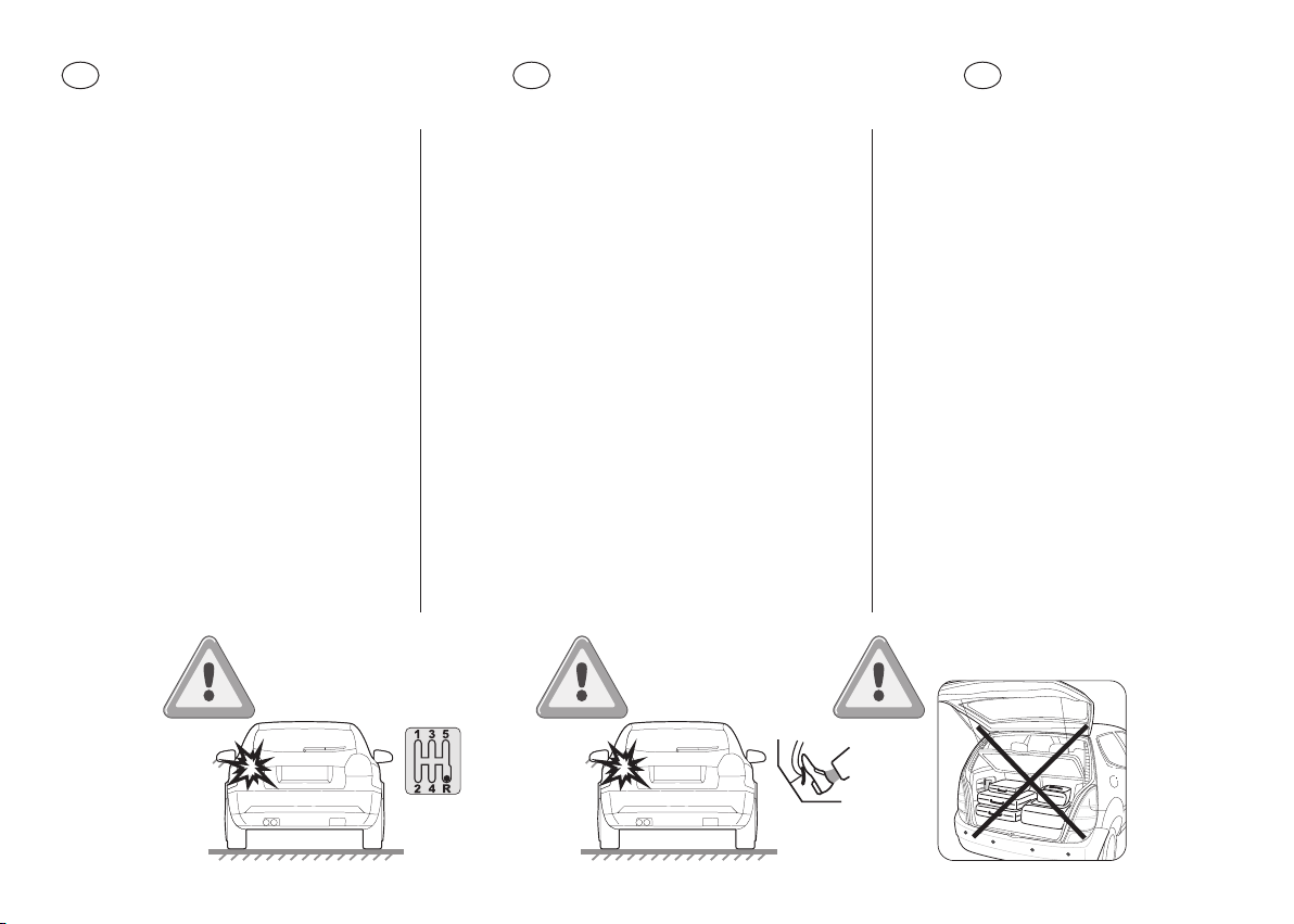
EN
FR
ES
Caution
• It is recommended that installation
is carried out by an approved
professional auto technician.
• Fit the correct the angle ring (included
in the kit) in order to obtain the
required inclination in the range of
+/- 5° after installation on the vehicle
bumper (see installation p23).
• Pay attention to the jumper setting
(ECU) according to your usage
(see section p29).
• Always keep the sensor clean as it
may aect the detection.
• It is strongly advised to check the
position of the sensors before the
denitive drilling of the holes.
• Valeo beep&park® helps provide
assistance when reversing and
parking. Driving skills, such as slowing
down, use of mirrors etc. are always
essential.
Attention
• Il est recommandé de faire eectuer
l’installation par un professionnel de
l’électricité automobile.
• Installer la bonne bague correctrice
d’angle (présent dans le kit) an
d’obtenir une inclinaison de capteur
compris entre +/- 5° sur le pare-choc
(voir p.23).
• Porter une attention sur le montage
des cavaliers (sur l’ECU) en accord
avec votre utilisation (voir p.29).
• Toujours maintenir les capteurs
propores pour une detection optimale.
• Il est fortement conseillé de vérier
la position des capteurs avant de
percer le pare-choc.
• Le système Valeo beep&park® aide
le conducteur à manoeuvrer et se
garerLa vigilance du conducteur est
cependant impérative (utiliser les
rétroviseurs, etc…).
Precauciones
• Se recomienda que la instalación
sea llevada a cabo por un Mecánico
Profesional Certicado.
• Instalar el anillo de ángulo correcto
(incluido en el kit) para obtener la
inclinación requerida en el rango
de +/- 5° después de la instalación
en el parachoques del vehículo
(ver instalación p23).
• Preste atención a la conguración del
parachoques en la Unidad Electrónica
de Control según su uso (
• Mantenga siempre el sensor limpio,
ya que puede afectar a la detección.
• Se recomienda encarecidamente
comprobar la posición de los sensores
antes de la perforación denitiva
de los oricios.
• Valeo beep & park® ayuda a proporcionar
asistencia en la marcha atrás y
estacionamiento. Las habilidades de
conducción, como la ralentización, el uso
de espejos, etc., son siempre esenciales.
Ver página p29)
.
12

IT14CS PL HU
DE
NL
Raccomandazioni
• Si raccomanda l’installazione da parte
di un tecnico auto professionista
e approvato.
• Inserire l’anello corretto (incluso
nel kit) per ottenere l’inclinazione
desiderata nell’intervallo di +/- 5°
dopo l’installazione sul paraurti
del veicolo (vedi installazione p23).
• Prestare attenzione al collegamento
del ponte (ECU) secondo l’utilizzo
desiderato
• Mantenere sempre i sensori puliti
poichè potrebbe inuenzare il
rilevamento.
• Si consiglia caldamente di controllare la
posizione dei sensori prima di praticare
i fori denitivamente.
• Valeo beep&park® fornisce assistenza
quando si eettua la retromarciamarcia o
un parcheggio. Le capacità di guida, come
rallentare, controllare gli specchietti etc.
sono comunque essenziali.
(
Vedi la sezione a p29)
.
Vorsicht
• Es wird empfohlen den Einbau von
einem zugelassenen & professionellen
KFZ-Betrieb durchführen zu lassen.
• Setzen Sie den Winkelring (im
Lieferumfang enthalten) ein, um die
erforderliche Neigung im Bereich
von +/- 5 ° nach der Montage am
Fahrzeugstoßfänger zu erhalten
(siehe Einbau seite 23).
• Achten Sie auf die Einstellung des
Schalters für Front- oder Heckmodus (ECU)
gemäß Ihrer Nutzung
• Halten Sie den Sensor immer sauber,
da er die Erkennung beeinussen kann.
• Es wird dringend empfohlen, die Position
der Sensoren vor dem endgültigen
Bohren der Löcher zu überprüfen.
• Valeo beep&park® ist eine Hilfe für
Parkmanöver. Dieses Produkt ist kein Ersatz
für die Wachsamkeit und Fähigkeiten des
Fahrers. Geringe Geschwindigkeiten, die
Nutzung der Außen- und des Rückspiegels
etc. ist weiterhin notwendig.
(
Siehe Seite p29)
.
Waarschuwing
• Laat het systeem bij voorkeur
inbouwen door een erkende,
professionele automonteur.
• Monteer de juiste stelring (in de set
inbegrepen) om de juiste hoek (+/- 5°)
te bereiken na montage in de bumper
van het voertuig (zie Montageinstructies p23).
• Let op de instelling van de jumper
op de ECU, aankelijk van het soort
gebruik
(
zie gedeelte pagina 29)
• Houd de sensoren altijd schoon;
vuil kan invloed hebben op de
detectieprestaties van de sensoren.
• Controleer de positie van de sensoren
voordat u gaten boort.
• Valeo beep&park® helpt de bestuurder
bij het achteruitrijden en parkeren.
Acties van de bestuurder, zoals
afremmen en het gebruik van spiegels,
blijven echter essentieel.
.
13
Varování
• Doporučuje se, aby instalaci prováděla
odborně způsobilá osoba.
• Po instalaci do nárazníku namontujte
správnou pdoložku pro nastavení ůhlu
(obsažena v balení), abyste dosáhli
požadovaného sklonu +/-5° - viz montáž.
• Dejte pozor na správné nastavení
propojení s ECU, dle Vašeho použití
(viz sekce strana p29)
• Pro zajištění optimální detekce
udržujte snímač čistý.
• Důrazně doporučujeme kontrolu
polohy snímačů před nálním
vyvrtáním otvorů.
• Valeo beep&park® pomáhá při couvání
a parkování. Dovednosti řidiče jako
je zpomalování, sledování zpětných
zrcátek jsou vždy nezbytné.
.
Ostrzeżenia
• Zaleca się instalację systemu przez
profesjonalistę.
• Umieść podkładki kątowe (zawarte
w zestawie) w celu uzyskania
odpowiedniego nachylenia w zakresie
+/- 5° po zamontowaniu zderzaka
(
Patrz strona p23)
• Zwróć uwagę na umiejscowienie
zworki w centralce ECU w zależności
od trybu użytkowania (patrz instalacja).
• Zawsze utrzymuj czujniki czyste
ponieważ zabrudzenia mogą wpłynąć
na jakość detekcji.
• Zaleca się sprawdzenie
umiejscowienia czujników przed
wykonaniem otworów w zderzaku.
• Valeo beep&park® zapewnia pomoc
w cofaniu oraz parkowaniu jednak
ostrożność na drodze, odpowiednia
prędkość oraz używanie lusterek są
zawsze konieczne.
.
Figyelmeztetés
• Ajánlatos az installáció elvégzését
képzett szerelőre bízni.
• Használjuk a helyes szögbeállító
gyűrűt (a készlet része), hogy a kívánt
dőlést +/-5° tartományban elérjük
a jármű lökhárítójának felszerelését
követően
(lásd a p23 fejezetet).
• Figyeljünk a lökhárító - alkalmazásnak
megfelelő - helyes felszerelésére
(ECU) lásd: installáció.
• A szenzort folyamatosan tisztán
kell tartani, mert a szennyeződés
befolyásolhatja a felismerést.
• Nyomatékosan ajánljuk a szenzorok
helyzetének ellenőrzését a lyukak
végleges kifúrása előtt.
• Valeo beep&park® segíti a
járművezetőt tolatáskor, parkoláskor.
A járművezető ismeretei, a jármű
lassítása, a tükrök használata, stb.
ettől függetlenül minden esetben
elengedhetetlenek.

EN
Box content
FR
ES
DE
NL
CS
PL
Contenu du pack
Contenido de la caja
IT
Contenuto della scatola
Verpackungsinhalt
Inhoud verpakking
Obsah balení
Zawartość opakowania
HU
A készlet tartalma
15
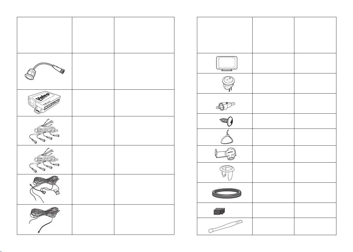
Item Quantity Spare part ref
Item Quantity Spare part ref
x8
632205 – black (x1)
632206 – black shiny (x1)
632207 – silver (x1)
x1 632216
632208 – dark grey (x1)
632214 – paintable (x1)
x1 -
A
B
C
D
Ø 18,8 mm
X1 632222
x1 -
x2 -
x1 -
x15 -
E
F
G
H
x4 -
x1 -
0° x8
4° x8
632226
10° x8
x1 -
Black x8
Grey x8
-
Transparent x8
jumper
x2 -
x1 -
x1 -
16

EN
Tools needed
FR
ES
DE
NL
CS
PL
Outils nécessaires
Herramientas necesarias
IT
Attrezzi necessari
Werkzeuge benötigt
Benodigd gereedschap
Potřebné nářadí
Niezbędne narzędzia
HU
Szükséges szerszámok
17
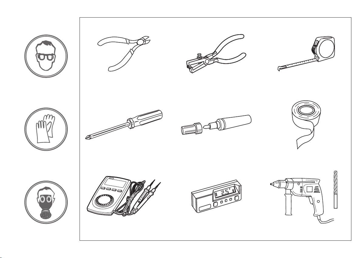
Ø 3 mm
18

EN
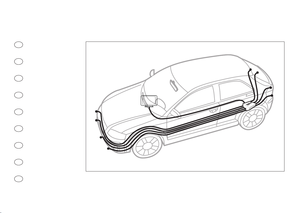
Set up sensors on bumper (front/rear)
FR
ES
DE
NL
CS
PL
Installer les capteurs dans le pare-choc (avant/arrière)
Conguración de los sensores en parachoque (delanteros/traseros)
IT
Montaggio dei sensori sul paraurti (anteriore/posteriore)
Einstellen der Sensoren (Front-/Heckmodus)
Montage sensoren op bumper (voor/achter)
Nastavení senzoru v nárazníku (přední/zadní)
Umieść czujnik na zderzaku (przód/tył)
HU
Szenzorok beállítása a lökhárítón (elöl és hátul)
19
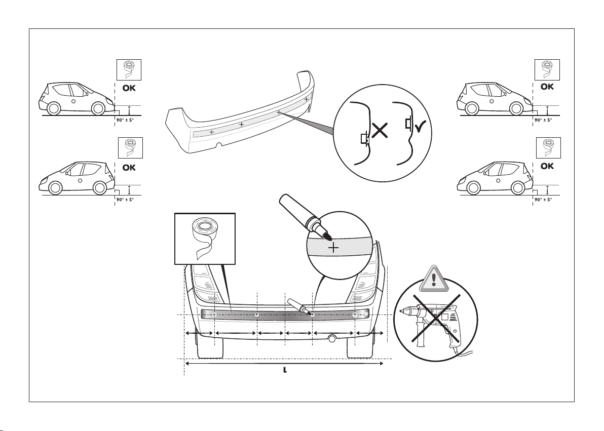
H=50cm
H>40cm
H<65cm
H=50cm
H>40cm
H<65cm
A A A A2A 2A
A = 1/8 L = 22 cm max
20

Ø 3 mm
Ø 18,8 mm
21

22

EN
Choose the correct angle ring
FR
ES
DE
NL
CS
PL
Choisir la bonne bague correctrice d’angle
Elija el anillo angular correcto
IT
Scegliere l’anello corretto
Wählen Sie den korekten Winkeleinstellring
Kies de juiste stelring
Výběr vhodné podložky pro nastavení úhlu
Wybierz odpowiednią podkładkę kątową
HU
Válasszuk ki a helyes dőlésszög beállító gyűrűt
23

0° / 4° / 10 °
H = 65 cm
H = 50 cm
H = 40 cm
H H
4°
10 °
0°
10 °
4°
+15°-15°
10 °
10 °
24

0°/4°/10°
p. 57
25

H
G
E
26
F

Check the inclination +/-5°
Vérier l’inclinaison +/-5°
Vericar la inclinación +/-5º
Vericare l’inclinazione di +/-5°
Prüfen Sie die Neigung (+/- 5°)
Controleer de hoek (+/- 5°)
Kontrola sklonu +/-5°
Sprawdź kąt nachylenia +/-5°
H
G
F
E
Ellenőrizzük a +/-5° tartományban
a dőlés szögét
D
C
B
A
27

28

EN
Set up the jumper on ECU (front/rear mode - tow bar o-set - sensitivity)
FR
ES
DE
NL
CS
PL
Positionner les cavaliers sur l’UCE (montage avant ou arrière - correction attache remorque - sensibilité)
Congurar el parachoques en la UEC (modo delantero / trasero - ajuste del enganche de remolque - sensibilidad)
IT
Predisporre il ponte nella centralina ECU (montaggio anteriore/posteriore - compensazione barra di traino - sensibilità)
Wählen Sie die richtige Einstellung des Schalters am Steuergerät(Front- / Heckmodus - Anhängerkupplung - Empndlichkeit)
Jumper correct instellen op de ECU (montage voor/achter - aanwezigheid trekhaak - gevoeligheid)
Nastavení připojení s ECU (přední/zadní režim - tažné zařízení - citlivost)
Umieść zworę w ECU (tryb przedni/tylny - wykrywanie haka holowniczego)
HU
Állítsuk be a váltókábelt (jumper) az ECU-ra (jármű elején vagy végén – hátul a vonószerkezetet le kell szerelni,
ellenőrizzük a készülék érzékenységét)
29

1 1 1
2 2 2
3 3 3
A B C
1 1 1
2 2 2
3 3 3
A B C
Jumper
1 1 1
2 2 2
3 3 3
A B C
1 1 1
2 2 2
3 3 3
A B C
8 s
20 s
(Default setting)(Default setting)
1 1 1
2 2 2
3 3 3
A B C
1 1 1
2 2 2
3 3 3
A B C
STOP
30 cm
STOP
50 cm
High
sensitivity
1 1 1
2 2 2
3 3 3
A B C
(Default setting)
Low
sensitivity
1 1 1
2 2 2
3 3 3
A B C
30

EN
Connect the ECU (front/rear)
FR
ES
DE
NL
CS
PL
Connecter l’UCE (montage avant/montage arrière)
Conectar la UEC (delantero/trasero)
IT
Connessione alla centralina ECU (anteriore/posteriore)
Verbinden Sie das Steuergerät (Front / Heck)
Sluit de ECU aan (voor/achter)
Připojení ECU (přední/zadní)
Podłącz centralkę ECU (przód/tył)
HU
Csatlakoztassuk az ECU-t (elöl/hátul)
31

1 2 3 4
1/ Ground: black
2/ Brake light: white
with red stripes
3/ + Reverse: white
4/ +ACC: Pink
Reverse light
Feu marche arrière
Luz de marcha atrás
Brake light
Feu stop
Luz de freno
Bremslicht
Luce del freno
Remlicht
Brzdové světlo
Światło hamowania
Féklámpa
32
Luce posteriore
Rückfahrscheinwerfer
Achteruitijlamp
Světlo zpátečky
Światło cofania
Tolatólámpa kábel

A B C D E F G H
ABCDEFGH
E
F
G
H
A
B
C
D
33

34

EN
Set up Display
FR
ES
DE
NL
CS
PL
Installer l’écran
Congurar la pantalla
IT
Congurare il display
Einrichten der Anzeige
Congureren display
Nastavení displeje
Doposażenie w wyświetlacz
HU
Állítsuk be a kijelzőn
35

ABCDEFGH
0123
X4
Min Max
5s
36
> 5 s > 5 s
m in

EN
Functional tests
FR
ES
DE
NL
CS
PL
Essais de fonctionnement
Pruebas de funcionalidad
IT
Test di funzionamento
Funktionstest
Functietests
Test funkcí
Test funkcjonowania
HU
Funkció teszt
37

1.5 m
38
< 0.9 m

EN
False detection may occur in such cases (front/rear)
FR
ES
DE
NL
CS
PL
Risque d’erreur de détection dans les cas suivants
Falsa detección podría ocurrir en esos casos
IT
In questi casi può vericarsi un falso rilevamento dell’ostacolo
Eine fehlerhafte Erkennung kann bei folgenden Fällen auftreten
Onjuiste detectie kan voorkomen in deze gevallen
K chybné detekci může dojít v těchto případech
Nieprawidłowa detekcja może wystąpić w następujących przypadkach
HU
Hibás érzékelés előfordulhat az alábbi esetekben
39

FRONT REAR
D
A
B
C
False detection may occur in such cases:
Risque d’erreur de détection dans
les cas suivants :
Puede darse una falsa alarma en estos casos:
In questi casi può vericarsi un falso
rilevamento dell’ostacolo:
In diesen Fällen können Fehlmessungen erfolgen:
In de volgende gevallen werkt het
detectiesysteem mogelijk niet optimaal:
K chybné detekci může dojít v těchto případech:
Nieprawidłowa detekcja może wystąpić
w następujących przypadkach :
Hibás érzékelések előfordulhatnak
az alábbi esetekben:
40

EN
Self diagnosis
FR
ES
DE
NL
CS
PL
Auto-diagnostique
Autodiagnóstico
IT
Auto diagnosi
Selbstdiagnose
Zelfdiagnose
Samodiagnostika
Autodiagnostyka
HU
Öndiagnosztika
41

FRONTREAR
AA
BFCGDD
E
42
H

EN
Troubleshooting
FR
ES
DE
NL
CS
PL
Dépannage
Solución de problemas
IT
Riparazione del guasto
Fehlerbehebung
Storing zoeken
Odstraňování problémů
Rozwiązywanie problemów
HU
Hibaelhárítás
43

EN FR
Troubleshooting Dépannage
Once reverse gear is selected,
a sound signal is triggered when
there is no obstacle behind the
vehicle:
1- Check that requested height of
sensors tted on the bumper from
the oor is respected (between
45 and 60 cm).
2- Check that requested angle of
sensors tted on the bumper
is respected. If necessary, use
the angle correction rings for
the installation.
3- Check that requested distance
between sensors on the bumper
is respected (< or = 45 cm).
Once reverse gear is selected,
an obstacle behind the vehicle
is not detected by the system:
1- Check that requested height of
sensors tted on the bumper from
the oor is respected (between
45 and 60 cm).
2- Check that requested angle of
sensors tted on the bumper
is respected. If necessary, use
the angle correction rings for
the installation.
3- Check that requested distance
between sensors on the bumper
is respected (< or = 45 cm).
44
4- Check the display is not on
mute mode (go to page 35).
The system indicates a defective
sensor (the display beeps 3 times):
1- Check whether the sensor surface
is clean.
2- Check whether the sensor wires
are plugged in the ECU properly.
3- Check whether the sensor wires
are damaged or not.
4- Check that the sensor is not damaged.
5- Check that the sensor cables are
connected to the control unit
(ECU) in the correct order (markers
ABCDEFGH).
Volume of the audible alert is too
low:
1- Select the maximum level and check
if is at the desired level.
If the problem persists, please
follow these steps:
1-Check the wiring connection.
2- Check the ECU setting (jumper
selection).
3- Contact the dealer where you
purchased the product
If 2 consecutives sensors are
in default, the full system will
be set o.
Une fois la marche arrière
enclenchée, l’alerte sonore se
déclenche alors qu’il n’y a pas
d’obstacle derrière le véhicule :
1- Vérier que la hauteur des capteurs
sur le pare-chocs par rapport au sol
est respectée (entre 45 et 60 cm).
2- Vérier que l’angle d’installation
des capteurs sur le pare-chocs
est respecté. Si besoin, ajouter des
bagues d’adaptation pour corriger
l’angle.
3- Vérier que la distance entre les
capteurs sur le pare-chocs a été
respectée (< ou = à 45 cm).
Une fois la marche arrière enclenchée,
le système ne détecte pas l’obstacle
présent derrière le véhicule :
1- Vérier que la hauteur des capteurs
sur le pare-chocs par rapport au sol
est respectée (entre 45 et 60 cm).
2- Vérier que l’angle d’installation
des capteurs sur le pare-chocs est
respecté. Si besoin, ajouter des
bagues d’adaptation pour corriger
l’angle.
3- Vérier que la distance entre les
capteurs sur le pare-chocs a été
respectée (< ou = à 45 cm).
4- Vérier que l’écran n’est pas en
sourdine (voir p.35).
Le système indique un capteur
défectueux (l’écran émet un bip
3 fois) :
1- Vérier que la surface du capteur
est propre.
2- Vérier que les ls du capteur sont
bien branchés sur l’ECU.
3- Vérier l’état des ls du capteur.
4- Vérier que le capteur n’a pas été
endommagé.
5- Vérier que les ls du capteur sont
branchés sur l’ECU dans le bon ordre
(repères ABCDEFGH).
Le volume de l’alerte sonore
est trop faible :
1- Sélectionnez le niveau maximum et
vériez s’il est au niveau souhaité.
Si le problème persiste, procéder
comme suit :
1- Vérier l’installation du câblage.
2- Vérier le paramétrage de l’UCE
(sélection des cavaliers)
3- Contacter le revendeur où le produit
a été acheté
Si 2 capteurs ne fonctionnent pas
consécutivement, recommencez
le branchement du système.

ES IT
Solución de problemas Riparazione del guasto
Una vez puesta la marcha atrás,
el pitido suena cuando no hay
obstáculos detrás del vehículo:
1- Compruebe que la altura entre los
sensores y el suelo es respetada
(entre 45 y 60 cm).
2- Compruebe que el ángulo de posición
de los sensores es respetado.
Si fuera necesario añadir una anilla
de ajuste para corregir el ángulo.
3- Compruebe que la distancia entre los
sensores ha sido respetada (< o = 45 cm).
Una vez puesta la marcha atrás,
el sistema no detecta obstáculos
detrás del vehículo:
1- Compruebe que la altura entre los
sensores y el suelo es respetada
(entre 45 y 60 cm).
2- Compruebe que el ángulo de posición
de los sensores es respetado.
Si fuera necesario añadir una anilla
de ajuste para corregir el ángulo.
3- Compruebe que la distancia entre los
sensores ha sido respetadas
(< o = 45 cm).
4- Compruebe que la pantalla no está
en el modo de silenciamiento
(ir a la página 35).
El sistema indica un sensor
defectuoso (la pantalla suena
3 veces):
1- Compruebe que la supercie del
sensor está limpia.
2- Compruebe que los cables del sensor
estén enchufados a la centralita
correctamente.
3- Compruebe que los cables del sensor
no estén dañados.
4- Compruebe que el sensor no esté
dañado.
5- ¿Están los cables del sensor
conectado a la unidad de control
(Centralita) en el orden correcto
ABCDEFGH).
El sonido de alerta es demasiado bajo:
1- Seleccione el nivel máximo y
asegúrese de que está en el nivel
deseado.
Si el problema persiste, por favor,
siga estos pasos:
1- Verique la conexión del cableado.
2- Revise la denición del ECU (puente
de comprobación).
3- En contacto con el distribuidor donde
compró el producto.
Si 2 sensores consecutivos están
defectuosos, el sistema se apagará
completo.
Una volta inserita la retromarcia,
l’allarme sonoro si disattiva se non
ci sono ostacoli dietro il veicolo:
1- Vericare che l’altezza dei sensori
sul paraurti rispetto al suolo sia
rispettata (fra 45 e 60 cm).
2- Vericare che l’angolo di
installazione dei sensori sul paraurti
sia stato rispettato. Se necessario,
aggiungere il correttore d’angolo
per correggere l’angolo.
3- Vericare che la distanza tra i
sensori sul paraurti sia stata
rispettata (< o = 45 cm).
Una volta inserita la retromarcia,
il sistema non rileva l’ostacolo
dietro al veicolo:
1- Vericare che l’altezza dei sensori
sul paraurti rispetto al suolo sia
rispettata (fra 45 e 60 cm).
2- Vericare che l’angolo di installazione
dei sensori sul paraurti sia stato
rispettato. Se necessario, aggiungere
il correttore d’angolo per correggere
l’angolo.
3- Vericare che la distanza tra i sensori
sul paraurti sia stata rispettata
(< o = 45 cm).
4- Controllare che il display non sia in
modalità muta (vai a pagina 35).
Il sistema indica un sensore
difettoso (il display emette un
segnale acustico 3 volte):
1- Vericare che la supercie dei
sensori sia pulita.
2- Vericare che i cavi dei sensori
siano correttamente collegati all’ECU.
3- Vericare lo stato dei cavi del
sensore.
4- Vericare che il sensore non sia
danneggiato.
5- Vericare che il cavo del sensore
sia correttamente collegato all’ECU
nell’ordine corretto (riferimento
ABCDEFGH).
Il volume dell’allarme sonoro
è troppo basso:
1- Selezionare il massimo livello e
vericare che sia al livello desiderato..
Se i problemi persistono, seguite
questi consigli:
1- Controllare la corretta connessione
dei cavi.
2- Controllare l’impostazione della
centralina ECU (selezione ponte).
3- Contattare il rivenditore dove
si è acquistato il prodotto.
Se 2 sensori consecutivi sono
in default, l’intero sistema verrà
disattivato.
45

DE NL
Fehlerbehebung Storing zoeken
Sobald der Rückwärtsgang eingelegt
ist, wird ein Warnsignal ausgelöst,
obwohl sich kein Hindernis hinter
dem Fahrzeug bendet:
1- Stellen Sie sicher, dass der erforderliche
Abstand der Sensoren vom Boden für
die Einpassung in die Stoßstange
berücksichtigt wurde (zwischen 45
und 60 cm).
2- Kontrollieren Sie den Winkel der in die
Stoßstange eingepassten Sensoren.
Falls notwendig, benutzen Sie die
Winkeleinstellringe.
3- Vergewissern Sie sich, dass der Abstand
zwischen den einzelnen Sensoren an
der Stoßstange korrekt ist (< oder = 45 cm).
Obgleich der Rückwärtsgang
eingelegt ist, erkennt das System
kein Hindernis hinter dem Fahrzeug:
1- Stellen Sie sicher, dass der erforderliche
Abstand der Sensoren vom Boden für
die Einpassung in die Stoßstange
berücksichtigt wurde (zwischen 45
und 60 cm).
2- Kontrollieren Sie den Winkel der in die
Stoßstange eingepassten Sensoren.
Falls notwendig, benutzen Sie die
Winkeleinstellringe.
3- Vergewissern Sie sich, dass der Abstand
zwischen den einzelnen Sensoren an
der Stoßstange korrekt ist (< oder =
45 cm).
4- Prüfen Sie, ob der Anzeige stumm
46
geschaltet ist (siehe Seite 35).
Das System weist auf einen defekten
Sensor hin (der Anzeige piept dreimal):
1- Überprüfen Sie, ob die
Sensoroberäche sauber ist.
2- Vergewissern Sie sich, dass die
Sensoren richtig mit dem Steuergerät
verbunden sind.
3- Kontrollieren Sie, ob die Sensorkabel
beschädigt sind.
4- Stellen Sie sicher, dass die Sensoren
unversehrt sind.
5- Vergewissern Sie sich, dass
die Sensoren in der richtigen
Reihenfolge (Markierungen
ABCDEFGH) mit dem Steuergerät
verbunden sind.
Die Lautstärke des Warntons
ist zu niedrig:
1- Wählen Sie die höchste Stufe aus
und prüfen Sie, ob es auf dem
gewünschten Niveau ist.
Wenn das Problem weiterhin besteht,
führen Sie bitte folgende Schritte
durch:
1- Prüfen Sie den Kabelanschluss.
2- Prüfen Sie die Einstellung des
Steuergeräts (Stellung des Pins).
3- Kontaktieren Sie den Händler, bei
dem Sie das Produkt gekauft haben.
Wenn 2 nebeneinander liegende
Sensoren fehlerhaft sind, wird das
gesamte System ausgeschaltet.
Als het voertuig in de
achteruitrijversnelling is geschakeld
en een geluidssignaal wordt
geactiveerd als er geen obstakel
achter het voertuig aanwezig is:
1- Controleer of de gemonteerde sensoren
op de voorgeschreven hoogte
geplaatst zijn (tussen 45 en 60 cm).
2- Controleer of de gemonteerde
sensoren in de voorgeschreven hoek
geplaatst zijn. Indien nodig, gebruik bij
de montage de speciale ringen om de
juiste hoek te bepalen.
3- Controleer of de gemonteerde sensoren
op de voorgeschreven afstand van
elkaar geplaatst zijn (< of = 45 cm).
Als het voertuig in de
achteruitrijversnelling is geschakeld
en een obstakel achter het voertuig
wordt niet gedetecteerd door het
system:
1- Controleer of de gemonteerde sensoren
op de voorgeschreven hoogte
geplaatst zijn (tussen 45 en 60 cm).
2- Controleer of de gemonteerde sensoren
in de voorgeschreven hoek geplaatst
zijn. Indien nodig, gebruik bij de
montage de speciale ringen om de
juiste hoek te bepalen.
3- Controleer of de gemonteerde
sensoren op de voorgeschreven
afstand van elkaar geplaatst zijn
(< of = 45 cm).
4- Controleer of de display niet in mute
modus staat (ga naar pagina 35).
Het systeem geeft een defecte sensor
aan (de display piept drie keer):
1- Controleer of het sensoroppervlak
schoon is.
2- Controleer of de bedrading van de
sensoren juist is aangesloten op de ECU.
3- Controleer of de bedrading van de
sensoren beschadigd is.
4- Controleer of de sensor beschadigd is.
5- Controleer of de kabels van de
sensoren in de juiste volgorde
(ABCDEFGH) zijn aangesloten op
de ECU.
Het volume van het
waarschuwingssignaal is te laag:
- Selecteer het maximum niveau en
controleer.
Volg deze stappen als het
probleem zich blijft voordoen:
1- Controleer alle bedrading van het
systeem
2- Controleer de jumper instelling
op de ECU.
3- Neem contact op met de dealer
waar u bent.
Als twee naast elkaar
gemonteerde sensoren defect
zijn, wordt het gehele systeem
uitgeschakeld.

CS PL
Odstraňování problémů Rozwiązywanie problemów
Při zařazení zpátečky se spustí
zvukový signál informující o tom,
že za vozidlem není žádná překážka:
1- Překontrolujte, zda odpovídají
požadované výšky senzorů od země
montovaných do nárazníku (mezi 45
a 60 cm).
2- Překontrolujte, zda odpovídají
požadované úhly senzorů
montovaných do nárazníku. V případě
potřeby použijte pro instalaci kroužky
pro korekci úhlu.
3- Překontrolujte, zda odpovídají
požadované vzdálenosti mezi
senzory v nárazníku (< nebo = 45 cm).
Při zařazení zpátečky systém
nedetekuje překážku za vozidlem:
1- Zkontrolujte, zda je respektována
požadovaná výška snímačů od
podlahy (40 - 60cm).
2- Zkontrolujte, zda je dodržen
požadovaný úhel snímačů
namontovaných na nárazníku. V
případě nutnosti použijte podložky
pro nastavení úhlu.
3- Zkontrolujte, zda je dodržena
požadovaná vzdálenost mezi snímači
v nárazníku (min. 45cm).
4- Zkontrolujte, zda displeje není
v režimu ztlumení zvuku (přejděte
na stranu 35).
Systém indikuje poškozený senzor
(displeje třikrát pípne):
1- Překontrolujte, zda je čistý povrch
senzorů.
2- Překontrolujte, zda jsou vodiče
senzorů správně připojeny do ECU.
3- Překontrolujte, zda jsou či nejsou
poškozeny vodiče senzorů.
4- Překontrolujte, zda senzory nejsou
poškozeny.
5- Překontrolujte, zda jsou kabely
senzorů připojeny k řídicí jednotce
(ECU) ve správném pořadí (označení
ABCDEFGH).
Hlasitost akustického upozornění
je příliš nízká:
1- Zvolte maximální úroveň a
zkontrolujte, zda je na požadované
úrovni.
Pokud problémy setrvávají, proveďte
prosím následující kroky:
1- Zkontrolujte zapojení kabelů.
2- Zkontrolujte nastavení ECU (výběr
jumperu).
3- Kontaktujte Vašeho prodejce.
Pokud jsou 2 po sobě jdoucí
čidla výchozí, dojde k deaktivaci
systému.
Po włączeniu biegu wstecznego
sygnał dźwiękowy uruchamiany jest
przy braku przeszkody za pojazdem:
1- Sprawdzić, czy zachowana jest
wymagana wysokość instalacji
czujników zamontowanych na
zderzaku względem podłoża
(pomiędzy 45 a 60 cm).
2- Sprawdzić, czy zachowany jest
wymagany kąt instalacji czujników
zamontowanych na zderzaku. W razie
potrzeby użyć do instalacji pierścieni
korekty kątowej.
3- Sprawdzić, czy zachowana jest
wymagana odległość pomiędzy
czujnikami na zderzaku (< lub = 45 cm).
Po włączeniu biegu wstecznego
system nie wykrywa przeszkody
za pojazdem:
1- Sprawdzić, czy zachowana jest
wymagana wysokość instalacji
czujników zamontowanych na
zderzaku względem podłoża
(pomiędzy 45 a 60 cm).
2- Sprawdzić, czy zachowany jest
wymagany kąt instalacji czujników
zamontowanych na zderzaku. W razie
potrzeby użyć do instalacji pierścieni
korekty kątowej.
3- Sprawdzić, czy zachowana jest
wymagana odległość pomiędzy
czujnikami na zderzaku (< lub = 45 cm).
4- Sprawdzić czy wyświetlacz nie jest
wyciszony (patrz strona 35).
System wskazuje wadliwy czujnik
(wyświetlacz odzywa się 3 razy):
1- Sprawdzić, czy powierzchnia czujnika
jest czysta.
2- Sprawdzić, czy przewody czujnika są
prawidłowo podłączone do ECU.
3- Sprawdzić, czy przewody czujnika nie
są uszkodzone.
Sprawdzić, czy czujnik nie jest uszkodzony.
4-
5- Sprawdzić, czy kable czujnika są
podłączone do układu sterowania
(ECU) w prawidłowej kolejności
(oznaczenia ABCDEFGH).
Głośność ostrzeżenia dźwiękowego
jest za mała:
1- Ustaw maksymalny poziom i sprawdź
czy jest zgodny z oczekiwanym.
Jeśli problemy będą się powtarzać
prosimy postępować według
następujących punktów:
1- Sprawdzić podłączenie okablowania.
2- Sprawdzić ustawienia ECU (wybór
odpowiedniego zworka).
3- Skontaktuj się z dystrybutorem,
u którego został dokonany zakup.
Ważna uwaga: Jeśli dwa sąsiednie
czujniki są uszkodzone, cały
system zostanie wyłączony.
47

HU
Hibaelhárítás
A hátramenet kapcsolása után a
gyelmeztető jelzés megszólal
annak ellenére, hogy nincs akadály
a jármű mögött:
1- Ellenőrizze, hogy az érzékelők a
földhöz képest az előírt magasságon
vannak-e (45 és 60 cm között).
2- Ellenőrizze, hogy az érzékelők a
lökhárítón megfelelő szögben
vannak-e elhelyezve. Ha szükséges,
használjon szögátalakító
illesztőgyűrűt.
3- Ellenőrizze, hogy az érzékelők közti
előírt távolság be van-e tartva
(< vagy = 45 cm).
A hátramenet kapcsolása után a
rendszer nem ismeri fel a jármű
mögött található akadályt:
1- Ellenőrizze, hogy az érzékelők a
földhöz képest az előírt magasságon
vannak-e (45 és 60 cm között).
2- Ellenőrizze, hogy az érzékelők a
lökhárítón megfelelő szögben
vannak-e elhelyezve. Ha szükséges,
használjon dőlésszög átalakító
illesztő gyűrűt az installációhoz.
3- Ellenőrizze, hogy az érzékelők közti
előírt távolság adott-e (< vagy =
45 cm).
4- 4-Ellenőrizze, hogy a kijelzőn nincs-e
lenémítva (lapozza fel az 35 oldalt).
A rendszer szenzor meghibásodást
jelez: (3 kijelzőn hang)
1- Ellenőrizze, hogy az érzékelő felülete
tiszta-e.
2- Ellenőrizze, hogy az érzékelőkből
kivezető kábelek jól csatlakoznak-e
a központi egységhez (ECU).
3- Ellenőrizze, hogy a kábelek
nincsenek-e megsérülve.
4- Ellenőrizze, hogy az érzékelők
nincsenek-e megsérülve.
5- Ellenőrizze, hogy az érzékelők kábelei
helyes sorrendben csatlakoznak-e
(ABCDEFGH jelzés).
A gyelmeztető jelzés hangereje
túl alacsony:
1- Válassza ki a maximális szintet,
és ellenőrizze, hogy a kívánt szinten
van-e.
Ha a probléma nem szünik
meg, kérjük kövesse az alábbi
utasításokat:
1- Ellenőrizze a kábel csatlakozásokat.
2- Ellenőrizze az ECU beállításokat
(jumper).
3- Vegye fel a kapcsolatot a termék
forgalmazójával.
Ha 2 egymást követő szenzor hibás,
a teljes rendszer kikapcsol.
48

EN
Set up the radio mute function (optional)
Install radio mute function if the autoradio has a mute function
FR
ES
DE
NL
CS
PL
Désactiver la radio pendant le recul (option)
Conguración de la función de silencio
de la radio (opcional)
IT
Predisposizione della funzione muto per
Vérier que l’autoradio possède une entrée pour la fonction “Mute”
Instalación de la función de silencio de radio si el autorradio
tiene una función de silenciamiento
Installare la funzione muto se l’autoradio ha una funzione muto
l’autoradio (optional)
Einrichten der Radiostummschaltung (optional)
Congureren van de mute-functie van de autoradio
(optioneel)
Nastavení funkce ztlumení radia (volitelné)
Ustaw funkcję wyciszenia radia (opcjonalne)
Radiostummfunktion kann nur einfgestellt werden, falls das Autoradio
eine Stummschaltung besitzt.
Congureer de mute-functie van de autoradio als de autoradio
van een mute-functie is voorzien
Instalace funkce ztlumení rádia, pokud má radio funkci ztlumení zvuku
Zainstaluj funkcję wyciszania radia jeśli radio w aucie ma tę funkcję
HU
Állítsa be a rádión a némítás funkciót (opció)
Állítsa be a rádió némítás funkcióját, amennyiben az autórádión van ilyen funkció
49

Look at your radio installation notice to locate the correct pin
for “mute” function (positive/negative trigger).
BACK OF THE CD OR RADIO
Power and
Speaker
CD Changer
Po•1
Yellow
cable
FR
Verier dans la notice d’installation
de l’autoradio an de localiser l’entrée
pour la fonction «mute» de l’autoradio.
Observe su aviso de instalación de radio
ES
para localizar el pin correcto para la función
«silencio» (positivo / negativo).
Controllare le note di installazione
IT
dell’autoradio per localizzare lo spinotto
corretto per la funzione «muto»
(interruttore positivo/negativo)
Schauen Sie sich Ihre Bedienungsanleitung
DE
vom Autoradio an, um den richtigen Anschluss
für die Stummschaltung zu nden (positiver /
negativer Auslöser).
50
NL
Zie de montage-instructies van de
autoradio voor de juiste stekkerpen van de
mute-functie (positief/negatief signaal).
Prostudujte návod na instalaci radia,
CS
abyste našli správný kolík pro funkci
ztlumení zvuku (pozitivní/negativní)
Sprawdź instrukcję radia w swoim pojedzie
PL
aby znaleźć odpowiedni pin włączający
funkcję MUTE.
A rádió beépítési utasításában ellenőrizze,
HU
hogy a „mute“ (némítás) funkciót aktiváló
csatlakozó jó helyen van-e (pozitív/negatív
billentyű).
ABCDEFGH

EN
If mute function has signal connect the wire to the
If mute function has
FR
Si la fonction «Mute»a un signal
Si la fonction «Mute» a un signal à la
signal connect the wire to the
, il faut alors connecter l’extension sur le .
, il faut alors connecter l’extension sur la
.
Yellow
cable
ES
Si la función de silencio tiene señal
Si la función de silencio tiene señal
IT
Se la funzione «muto» ha un segnale
Se la funzione «muto» ha un segnale
Wenn die Stummschaltung Signal hat, verbinden Sie das Kabel mit dem .
DE
Wenn die Stummschaltung ein
NL
Als de mute-functie een
Als de mute-functie een
CS
Pokud je funkce ztlumení na
-signaal heeft, sluit de draad dan aan op .
-signaal heeft, sluit de draad dan aan op
Pokud je funkce ztlumení na
PL
Jeżeli funkcja MUTE pracuje na
Jeżeli funkcja MUTE pracuje na
HU
Ha a némítás funkció
ellel jelzett, csatlakoztassuk a kábelt az
conectar el cable a la
conectar el cable a la
collegare il cavo all’
collegare il cavo alla messa a
Signal hat, verbinden Sie das Kabel mit dem .
, připojte signál k .
, připojte signál k
.
.
przewodzie zasilającym, podłącz przewód do .
przewodzie masowym, podłącz przewód sygnałowy do
Ha a némítás funkció jellel jelzett, csatlakoztassuk a kábelt -höz.
-hoz.
.
.
51

52

EN
Tow bar
FR
ES
DE
NL
CS
PL
Attache remorque
Barra de remolque
IT
Barre di traino
Anhängerkupplung
Trekhaak
Tažným zařízením
Hak holowniczy
HU
Vonóhoroggal
53

10 s
X 10
X 1
1 1 1
2 2 2
3 3 3
A B C
Jumper
1 1 1
2 2 2
3 3 3
A B C
54
STOP
50 cm
1 1 1
2 2 2
3 3 3
A B C
High
sensitivity
(default setting)
1 1 1
2 2 2
3 3 3
A B C
Low
sensitivity
1 1 1
2 2 2
3 3 3
A B C

EN
Install the manual product desactivation (optional)
FR
ES
DE
NL
CS
PL
Installer un interrupteur de désactivation du sytème (optionnel)
Instalar la desactivación manual del producto (opcional)
IT
Installare la disattivazione manuale del prodotto (optional)
Einrichten der manuelle Produktdeaktivierung (optional)
Montage handbediende uitschakeling (optioneel)
Instalace ruční deaktivace (volitelné)
Ustawianie funkcji manualnego wyłączania (opcjonalnie)
HU
Installáljuk a készülék manuális hatástalanítását (opció)
55

ABCDEFGH
1 2 3 4
pink cable
1 2 3 4
1/ Ground: black
2/ Brake light: white
with red stripes
3/ + Reverse: white
4/ +ACC: Pink
56

EN
Instruction for painting the sensors (optional)
FR
ES
DE
NL
CS
PL
Instruction pour peindre les capteurs (optionnel)
Instrucciones para pintar los sensores (opcional)
IT
Istruzioni per verniciare i sensori (optional)
Anleitung zum Lackieren der Sensoren (optional)
Instructies voor het spuiten van de sensoren (optioneel)
Instrukce pro lakování snímačů (volitelné)
Instrukcja lakierowania czujników (opcjonalne)
HU
Tájékoztatás a szenzorok festéséhez (opció)
57

1
2 3
4
7 8
58
5 6
Important note: Check that the angle ring is correctly tted on the sensor.
Important: vérier que la bague correctrice d’angle est bien xée au capteur.
Nota importante: averiguar que el anillo corrector está correctamente
ajustado al sensor.
Nota importante: Controllare che l’ anello correttore dell’angolo
venga correttamente montato sul sensore.
Wichtiger Hinweis: Vergewissern Sie sich, dass der Außenring
korrekt auf dem Sensor angebracht ist.
Belangrijke aanwijzing: controleer of de buitenring correct op
de sensor is gemonteerd.
Důležité upozornění: Zkontrolujte, zda jsou správně namontované
podložky pro nastavení úhlu
Uwaga: Sprawdź, czy podkładka kątowa jest prawidłowo zamontowana
na czujniku.
Fontos útmutatás: Győződjön meg arról, hogy a beállító gyűrűt helyesen
szerelték fel az érzékelőre.
9

EN
Technical Parameters
FR
ES
DE
NL
CS
PL
Paramètres techniques
Parámetros técnicos
IT
Parametri tecnici
Technische Daten
Technische gegevens
Technické parametry
Parametry techniczne
HU
Műszaki jellemzők
59

EN FR ES
Technical Parameters Paramètres techniques Parámetros técnicos
• Rated voltage: from 9 to 16 V
• Sound level: 81dB / 75db / 69db
• Sound frequency: front mode: 1000 Hz
rear mode: 800 Hz
• Single shield wire harness (Sensors connected to ECU)
• Detecting range: 0.1 ~ 1.7 m
• Working current: ≤ 350 mA
• Sensor Working frequency: 40 KHz
• Operation temperature: - 40°C ~ + 85°C
• Homologation: E-mark, CE and ROHS, REACH
• MALSO compliant
• Plage de tension : 9 à 16 V
• Volume sonore : 81dB / 75db / 69db
• Fréquence sonore : mode avant : 1 000 Hz
mode arrière: 800 Hz
• Faisceau blindé (capteurs connectés à l’UCE)
• Zone de détection: 0.1 ~ 1.7 m
• Intensité de fonctionnement: ≤ 350 mA
• Fréquence de fonctionnement des capteurs : 40 KHz
• Température de fonctionnement : - 40°C ~ + 85°C
• Homologation: E-mark, CE et ROHS, REACH
• Conforme à la norme MALSO
• Tensión nominal: de 9 a 16 V
• Nivel de sonido: 81dB / 75db / 69db
• Frecuencia de sonido: modo frontal: 1000 Hz
modo trasero: 800 Hz
• Sólo una conexión (sensores conectados a la UCE)
• Distancia de detección: 0,1 ~ 1,7 m
• Corriente de trabajo: ≤ 350 mA
• Sensor Frecuencia de trabajo: 40 KHz
• Temperatura de funcionamiento: - 40°C ~ + 85°C
• Homologación: E-mark, CE and ROHS, REACH
• Conforme Norma MALSO
60

IT DE NL
Parametri tecnici Technische Daten Technische gegevens
• Tensione nominale: da 9 a 16 V
• Livello sonoro: 81dB / 75db / 69db
• Frequenza sonora: montaggio anteriore: 1 000 Hz
montaggio posteriore: 800 Hz
• Cavo schermato (Sensore connesso all’ECU)
• Spazio di rilevamento: 0.1 ~ 1.7 m
• Corrente di funzionamento: ≤ 350 mA
• Frequenza di funzionamento del sensore: 40KHz
• Temperatura di funzionamento: - 40°C ~ + 85°C
• Omologazione: E-mark, CE e ROHS, REACH
• Conforme MALSO
• Nennspannung: 9 - 16 V
• Lautstärke des Warnsignals: 81dB / 75db / 69db
• Klangfrequenz: Frontmodus: 1000 Hz
Heckmodus : 800 Hz
• Einfach abgeschirmter kabelbaum (sensoren
am steuergerät angeschlossen)
• Erfassungszone: 0.1 ~ 1.7 m
• Stromverbrauch: ≤ 350 mA
• Arbeitsfrequenz der Sensoren : 40KHz
• Betriebstemperatur: - 40°C ~ + 85°C
• Typprüfung: E-Kennzeichnung, CE and ROHS, REACH
• MALSO konform
• Nominale spanning: 9 - 16 V
• Geluidsniveau: 81dB / 75db / 69db
• Geluidsfrequentie: montage vóór: 1 000 Hz
montage achter: 800 Hz
• Enkel afgeschermde draadbundel (sensoren
aangesloten op ECU)
• Detectie bereik: 0.1 ~ 1.7 m
• Stroomsterkte (actief): ≤ 350 mA
• Frequentie sensoren (actief): 40 kHz
• Bedrijfstemperaturen: - 40°C ~ + 85°C
• Homologaties: E mark, CE en ROHS, REACH
• Conform MALSO-normen
61

CS PL HU
Technické parametry
• Jmenovité napětí: od 9 do 16V
• Hladina zvuku: 81dB / 75db / 69db
• Frekvence zvuku: přední režim: 1 000 Hz
zadní režim: 800 Hz
• Jeden stíněný kabelový svazek (Snímače zapojené do ECU)
• Rozsah detekce: 0,1 - 1,7m
• Pracovní proud: ≤ 350 mA
• Pracovní frekvence senzoru: 40KHz
• Pracovní teplota: - 40°C ~ + 85°C
• Homologace: E-značení, CE a ROHS, REACH
• V souladu s MALSO
Parametry techniczne Műszaki jellemzők
• Napięcie: od 9V do 16V
• Poziom dźwięku : 81dB / 75db / 69db
• Częstotliwość dźwięku: tryb przedni : 1 000 Hz
tryb tylny : 800 Hz
• Wiązka przewodów z pojedynczą osłoną (czujniki
podłączone do centralki ECU)
• Zakres detekcji: 0.1 ~ 1.7 m
• Pobór prądu: ≤ 350 mA
• Częstotliwość pracy czujnika : 40KHz
• Zakres temperatur pracy: - 40°C ~ + 85°C
• Homologacja: E-mark, CE oraz ROHS, REACH
• Zgodność z MALSO
• Névleges feszültség: 9 - 16 V
• Zajszint: 81dB / 75db / 69db
• Hangfrekvencia: elöl: 1 000 Hz
Használat a járművön hátul: 800 Hz
• Szimpla árnyékolású kábelre vonatkozó veszélyességi
besorolás (szenzorok az ECU_hoz csatlakoztatva)
• Észlelési tartomány: 0.1 ~ 1.7 m
• Üzemi áram: ≤ 350 mA
• Üzemi frekvencia az érzékelőn: 40 KHz
• Üzemeltetési hőmérséklet: - 40°C ~ + 85°C
• Homologizáció: E-jelzés, CE valamint ROHS, REACH
• MALSO megfelelőség
62

D C B A
Sensor cable
DCBA
HGFE
Sensors
H G F E
Mute control (Yellow)
1
GND
2
Brake light (white/red)
3
Reversing light (white)
4
ACC( +12V ) pink

632202
Conception et réalisation : – 09/2017
Valeo Service | 70, rue Pleyel | 93285 Saint-Denis Cedex
Valeo Service SAS au capital de 12 900 000 € - RCS Bobigny 306 486 408
 Loading...