

Page 1

DUOPRINT
Operating Manual
Page 2

Copyright by Carl Valentin GmbH / 7981005.1015
Information on the scope of delivery, appearance, performance,
dimensions and weight reflect our knowledge at the time of printing.
We reserve the rights to make modifications.
All rights, including those regarding the translation, are reserved.
No part of this document may be reproduced in any form (print,
photocopy or any other method) or edited, copied or distributed
electronically without written permission from Carl Valentin GmbH.
Due to the constant further development of our devices discrepancies
between manual and device can occur.
Please check www.carl-valentin.de for the latest update.
Trademarks
All named brands or trademarks are registered brands or registered
trademarks of their respective owners and may not be separately
labelled. It must not be concluded from the missing labelling that it is
not a registered brand or a registered trademark.
Carl Valentin label printers comply with the following safety guidelines:
CE
EG-Niederspannungsrichtlinie (2006/95/EG)
EG-Richtlinie Elektromagnetische Verträglichkeit (2004/108/EG)
Carl Valentin GmbH
Postfach 3744
D-78026 Villingen-Schwenningen
Neckarstraße 78 – 86 u. 94
D-78056 Villingen-Schwenningen
Phone
Fax
+49 7720 9712-0
+49 7720 9712-9901
E-Mail
Internet
[email protected]
www.carl-valentin.de
Page 3

DuoPrint Series Table of contents
10.15 Operating Manual 3
Table of Contents
Table of Contents ............................................................................. 3
1 Introduction ............................................................................ 5
1.1 General Instructions ................................................................ 5
1.2 Intended Use ........................................................................... 5
1.3 Product Description ................................................................. 6
2 Safety Instructions ................................................................ 7
2.1 Operating Conditions ............................................................... 8
3 Two-colour printing ............................................................. 13
3.1 Label Design .......................................................................... 13
3.2 Printhead 2 Offset.................................................................. 14
3.3 Label Photocells .................................................................... 14
3.4 Test Print ............................................................................... 15
3.5 Correcting the Printout .......................................................... 15
3.6 Material Savings - Labels ...................................................... 15
3.7 Colour Processing ................................................................. 16
3.8 Error Correction ..................................................................... 17
4 Technical Data ..................................................................... 19
4.1 Accessories ........................................................................... 21
4.2 Control inputs and outputs .................................................... 22
4.3 Plug & Play ............................................................................ 27
5 Installation ............................................................................ 29
5.1 Setting up the Label Printer ................................................... 29
5.2 Connecting the Label Printer ................................................. 30
5.3 Connector Pin Assignment (Printer Rear) ............................. 30
5.4 Start-Up ................................................................................. 31
6 Loading Media ..................................................................... 33
6.1 Loading Label Roll ................................................................. 33
6.2 Loading Label Roll with Option PA 8X .................................. 34
6.3 Loading Transfer Ribbon ....................................................... 35
7 Function Menu ..................................................................... 37
7.1 Keyboard ............................................................................... 37
7.2 Menu Structure ...................................................................... 38
7.3 Print settings .......................................................................... 41
7.4 Label layout ........................................................................... 42
7.5 Device settings ...................................................................... 44
7.6 Dispenser I/O (option) ........................................................... 46
7.7 Material Savings .................................................................... 50
7.8 Network ................................................................................. 52
7.9 Remote console ..................................................................... 52
7.10 Interface ................................................................................. 53
7.11 Date & Time ........................................................................... 54
7.12 Service Functions .................................................................. 55
7.13 Main menu ............................................................................. 58
8 Compact Flash Card / USB Memory Stick ........................ 59
8.1 General Information ............................................................... 59
8.2 Display Structure ................................................................... 59
8.3 Navigation .............................................................................. 60
8.4 Define User Directory ............................................................ 61
8.5 Load Layout ........................................................................... 62
8.6 File Explorer .......................................................................... 63
8.7 Firmware Update ................................................................... 68
8.8 Filter ....................................................................................... 68
Page 4

Inhaltsverzeichnis DuoPrint Serie
4 Operating Manual 10.15
9
Maintenance and Cleaning ................................................. 69
9.1 General Cleaning ................................................................... 70
9.2 Cleaning the Printer Roller .................................................... 70
9.3 Cleaning the Printhead .......................................................... 71
9.4 Cleaning the Label Photocell ................................................. 72
9.5 Replacing the Printhead ........................................................ 73
9.6 Adjusting the Printhead ......................................................... 75
10 Error correction ................................................................... 77
11 Additional Information ........................................................ 87
11.1 Column Printing ..................................................................... 87
11.2 Password Protection ............................................................. 88
11.3 Photocells .............................................................................. 90
12 Environmentally-Friendly Disposal ................................... 91
13 Index ..................................................................................... 93
Page 5
DuoPrint Series Introduction
10.15 Operating Manual 5
1 Introduction
1.1 General Instructions
Important information and instructions in this document are
designated as follows:
DANGER identifies an extraordinarily great and immediate
danger which could lead to serious injury or even death.
WARNING identifies a possible danger would could lead
to serious bodily injury or even death if sufficient
precautions are not taken.
CAUTION indicates a potentially dangerous situation
which could lead to moderate or light bodily injury or
damage to property.
NOTICE gives you tips. They make a working sequence
easier or draw attention to important working processes.
Gives you tips on protecting the environment.
Handling instruction
Optional accessories, special fittings
Time
Information in the display
1.2 Intended Use
The label printer is a state-of-the-art device which complies with the
recognized safety-related rules and regulations. Despite this, a danger
to life and limb of the user or third parties could arise and the label
printer or other property could be damaged while operating the device.
The label printer may only be used while in proper working order and
for the intended purpose. Users must be safe, aware of potential
dangers and must comply with the operating instructions. Faults, in
particular those which affect safety, must be remedied immediately.
Page 6

Introduction DuoPrint Series
6 Operating Manual 10.15
The label printer is solely intended to print suitable media which have
been approved by the manufacturer. Any other or additional use is not
intended. The manufacturer/supplier is not liable for damage resulting
from misuse. Any misuse is at your own risk.
Intended used includes heeding the operating manual, including the
maintenance recommendations/regulations specified by the
manufacturer.
NOTICE!
The complete documentation is included in the scope of
delivery on CD ROM and can also currently be found in the
internet.
1.3 Product Description
The label printer provides the ideal solution in which labels as well as
textiles and plastics can be printed in two colours with one working
process. With two printheads arranged one behind the other, labels
are printed with two different colours. The second printing unit is
equipped with ribbon saving function by default, i.e. the printhead is
raised and the transfer ribbon consumption is reduced to a minimum.
With 8 vector fonts, 6 bitmap fonts and 6 proportional fonts the label
printer has a large selection at different font types. It can be printed
inverse, in italic format or 90 degrees turned fonts.
The handling of our durable label printers is easy and comfortable.
The parameter settings are made with the keys of the foil keyboard. At
each time the display shows the current status.
Time-saving printer update is possible by interface. The label printer is
equipped with all usual interfaces such as Centronics, RS-232 as well
as USB 2.0 and Ethernet 10/100 Base-T. Two additional USB ports
for keyboard or scanner are also integrated as standard. The label
printer automatically recognizes by which interface it is controlled
The label printer is delivered with a printer driver and the free label
software Labelstar Office LITE. The software controls which parts of
the label are printed by the first or second printing unit. Existing labels
can be saved to a CF card or an USB stick, opened and/or modified
with a PC keyboard and finally stand-alone printed.
Page 7

DuoPrint Series Safety Instructions
10.15 Operating Manual 7
2 Safety Instructions
The label printer is designed for power supply systems of
110-230 V. Connect the label printer only to electrical outlets with a
ground contact.
Couple the label printer to devices using extra low voltage only.
Before making or undoing connections, switch off all devices involved
(computer, printer, accessories etc.).
Operate the label printer in a dry environment only and do not get it
wet (sprayed water, mist etc.).
Do not operate the label printer in explosive atmosphere and not in
proximity of high voltage power lines.
Operate the label printer only in an environment protected against
abrasive dust, swarf and other similar impurity.
In case of cleaning and maintenance with an open cover, ensure that
clothing, hair, jewellery and similar personal items do not contact the
exposed rotating parts.
The print unit can get hot during printing. Do not touch the printhead
during operation. Cool down the print unit before changing material,
removal or adjustment.
Carry out only the actions described in these operating instructions.
Any work beyond this may only be performed by the manufacturer or
upon agreement with the manufacturer.
Unauthorized interference with electronic modules or their software
can cause malfunctions.
Other unauthorized work or modifications to the label printer can
endanger operational safety.
Always have service work done in a qualified workshop, where the
personnel have the technical knowledge and tools required to do the
necessary work.
There are warning stickers on the label printers that draw your
attention to dangers. Therefore the warning stickers are not to be
removed as then you and others cannot be aware of dangers and may
be injured.
DANGER!
Danger to life and limb from power supply!
Do not open the casing.
Page 8

Safety Instructions DuoPrint Series
8 Operating Manual 10.15
2.1 Operating Conditions
Before initial operation and during operation these operating
conditions have to be observed to guarantee save and interferencefree service of our printers.
Therefore please carefully read these operating conditions.
Shipment and storage of our printers are only allowed in original
packing.
Installation and initial operation of printer is only allowed if operating
conditions were fulfilled.
Initial operation, programming, operation, cleaning and service of our
printers are only recommended after careful study of our manuals.
Operation of printer is only allowed by especially trained persons.
NOTICE!
Perform trainings regularly.
Content of the training are chapter 2.1 (Operating Conditions),
chapter 6 (Loading Media) and chapter 9 (Maintenance and
Cleaning).
These indications are also valid for someone else's equipment
supplied by us.
Only use original spare and exchange parts.
Please contact the manufacturer with respect to spare/wear parts.
CPU of printer is equipped with a lithium battery (type CR 2032) for
which the battery regulation is to apply. This regulation plans that
unloaded batteries have to be given to used battery collecting
containers of trade and public carries. In case that batteries were not
completely discharged you have to make arrangements for shortcircuits. At a shutdown of printer the battery has to be disposed in
either case separately from printer.
DANGER!
Danger of life by explosion!
Use non-conducting tools.
The installation place of printer should be even, free of vibration and
currents of air are to be avoided.
The printers have to be installed to ensure optimal operation and
servicing.
Instructions for
lithium battery
Conditions for
installation place
Page 9

DuoPrint Series Safety Instructions
10.15 Operating Manual 9
The installation of the power supply to connect our printers has to be
effected according to the international rules and regulations,
especially the recommendations of one of the three following
commissions:
International Electronic Commission (IEC)
European Committee for Electro technical Standardisation
(CENELEC)
Verband Deutscher Elektrotechniker (VDE)
Our printers are constructed according to VDE and have to be
connected to a grounded conductor. The power supply has to be
equipped with a grounded conductor to eliminate internal interfering
voltage.
Power line voltage and power line frequency: See type plate
Allowable tolerance of power line voltage:
+6% … −10% of nominal value
Allowable tolerance of power line frequency:
+2% … −2% of nominal value
Allowable distortion factor of power line voltage: <=5%
In case your net is infected (e.g. by using thyristor controlled
machines) anti-interference measures have to be taken. You can use
one of the following possibilities:
Provide separate power supply to our printers.
In case of problems please connect capacity-decoupled isolation
transformer or similar interference suppressor in front of our
printers.
Emitted interference according to EN 61000-6-3: 2007 industrial
sector
Interference voltage to wires according to EN 55022: 09-2003
Interference field power according to EN 55022: 09-2003
System perturbation according to EN 61000-3-2: 09-2006
Flicker according to EN 61000-3-3: 1955 + A1:2001 + A2:2005
Installation of
power supply
Technical data of
power supply
Anti-interference
measures
Stray radiation and
immunity from
disturbance
Page 10

Safety Instructions DuoPrint Series
10 Operating Manual 10.15
Immunity to interference according to EN 61000-6-2: 2005
industrial sector
Stray radiation against discharge of static electricity according to
EN 61000-4-2: 12-2001
Electromagnetic fields according to EN 61000-4-3: 11-2003,
ENV 50204: 03-1995
Fast transient burst according to EN 61000-4-4: 07-2005
Surge according to EN 61000-4-5: 12-2001
High-frequency tension according to EN 61000-4-6: 12-2001
Voltage interruption and voltage drop according to
EN 61000-4-11: 02-2005
NOTICE!
This is a machine of type A. This machine can cause
interferences in residential areas; in this case it can be required
from operator to accomplish appropriate measures and be
responsible for it.
All connecting lines have to be guided in shielded lines. Shielding has
to be connected on both sides to the corner shell.
It is not allowed to guide lines parallel to power lines. If a parallel
guiding cannot be avoided a distance of at least 0.5 m has to be
observed.
Temperature of lines between: −15 … +80 °C.
It is only allowed to connect devices which fulfil the request 'Safety
Extra Low Voltage' (SELV). These are generally devices which are
checked corresponding to EN 60950.
The data cables must be completely protected and provide with metal
or metallised connector housings. Shielded cables and connectors are
necessary, in order to avoid radiant emittance and receipt of electrical
disturbances.
Allowable lines
Shielded line:
4 x 2 x 0,14 mm² ( 4 x 2 x AWG 26)
6 x 2 x 0,14 mm² ( 6 x 2 x AWG 26)
12 x 2 x 0,14 mm² (12 x 2 x AWG 26)
Sending and receiving lines have to be twisted in pairs.
Maximum line length:
with interface V 24 (RS-232C) - 3 m (with shielding)
with Centronics - 3 m (with shielding)
USB - 3 m
Ethernet - 100 m
Stray radiation and
immunity from
disturbance
Connecting lines to
external machines
Installation of
data lines
Page 11

DuoPrint Series Safety Instructions
10.15 Operating Manual 11
To avoid inadmissible heating, free air convection has to be ensured.
Protection according IP: 20
Ambient temperature °C (operation): Min. +5 Max. +35
Ambient temperature °C (storage): Min. −20 Max. +60
Relative air humidity % (operation): Max. 80
Relative air humidity % (storage): Max. 80
(bedewing of printers not allowed)
We do not take any responsibility for damage caused by:
Ignoring our operating conditions and operating manual.
Incorrect electric installation of environment.
Building alterations of our printers.
Incorrect programming and operation.
Not performed data protection.
Using of not original spare parts and accessories.
Natural wear and tear.
When (re)installing or programming our printers please control the
new settings by test running and test printing. Herewith you avoid
faulty results, reports and evaluation.
Only specially trained staff is allowed to operate the printers.
Control the correct handling of our products and repeat training.
We do not guarantee that all features described in this manual exist in
all models. Caused by our efforts to continue further development and
improvement, technical data might change without notice.
By further developments or regulations of the country illustrations and
examples shown in the manual can be different from the delivered
model.
Please pay attention to the information about admissible print media
and the notes to the printer maintenance, in order to avoid damages
or premature wear.
We endeavoured to write this manual in an understandable form to
give and you as much as possible information. If you have any queries
or if you discover errors, please inform us to give us the possibility to
correct and improve our manual.
Air convection
Limit values
Guarantee
Page 12

Page 13

DuoPrint Series Two-colour printing
10.15 Operating Manual 13
3 Two-colour printing
For printing in a second colour, the DuoPrint is equipped with an
additional printing unit.
Figure 1
A = Front printhead
B = Rear printhead
3.1 Label Design
When creating a label, it must, in addition to the contents to be
printed, also be determined which contents are to be printed in the
second colour, i.e. by the rear printhead.
The procedure depends on the transfer of the label.
Creation and printing by using Labelstar PLUS
In Labelstar PLUS, it is not possible to highlight the objects to be
printed by using colours. Therefore, objects which are to be printed by
the rear printhead must be specifically marked. Mark the object by
using the right mouse button, select Properties from the context menu
and activate the check box Printhead 2 on the tab General.
For an optimum print result, integrated graphics must be available as
black and white graphics and be separated if necessary.
Page 14

Two-colour printing DuoPrint Series
14 Operating Manual 10.15
Creation by using (Windows) software Labelstar Office and
printing via the CV printer driver
It is possible to design labels as desired. Coloured contents in a
defined colour are recognised by the driver and edited for the rear
printhead.
Further information on the settings can be found in the printer driver’s
help menu.
NOTICE!
When creating the label, attention must be paid to the correct
setting of the label size and slot length. Incorrectly set values
may result in an offset within the print image.
Printer-internal variables
NOTE!
It is not possible to use internal counters and date variables on
the rear printhead as they are updated only at print start.
3.2 Printhead 2 Offset
For optimising the print image, an automatic offset can be set for the
rear printhead. Under Service Functions/PH2 Offset, a x- and a y-
offset can be set.
Changes to this parameter alter the relative adjustment of the print
contents of the front and rear printheads.
3.3 Label Photocells
Each printhead has its own label light barrier in order to identify the
beginning of the label. Depending on the type of material, the light
barriers require different level values, which can be set separately.
NOTICE!
The two level values must be set correctly otherwise, the prints
may be incorrect.
Page 15

DuoPrint Series Two-colour printing
10.15 Operating Manual 15
3.4 Test Print
The print is only ever printed at one of the two printheads. The output
is controlled by the state of the rear printhead.
Printhead down = The test print is printed at the rear printhead.
Printhead up = The test print is printed at the front printhead.
3.5 Correcting the Printout
Mechanical tolerances may result in a shift in the printout. These
deviations can be corrected temporarily by setting the X and Y offsets.
The set offset has an effect on both printheads. With the function
Printhead 2 Offset the printouts of the front printhead and the rear
printhead can be corrected to each other.
A permanent shift of the printout is possible with the menu Service
functions/Zero point adjustment.
3.6 Material Savings - Labels
As the print images are printed at different positions on the label, a
minimal amount of label material is lost when the printing process has
been started. This is unavoidable, since rewinding the label material is
not possible for reasons of a safe material feeding process.
In order to prevent material losses during the ongoing print job, it is
possible to activate the Label Save Mode. More settings can be
specified in the menu Material savings/Label save mode.
Mode: Dialog
After a label is completely printed the printer examines whether
sufficient data is available in order to print the next label completely. If
this is not the case then the printing is stopped.
If a follow-up order is transferred the print is continued automatically
without a loss of material.
By pressing the key
the waiting status is terminated and all
remaining labels between the printheads are printed. Afterwards are
blank labels between the printhead. At a later print start this leads to a
loss of material.
Mode: Auto
Stopping the print at missing data is effected in the same way as in
operating mode Dialog.
If no further data follow the remaining labels are printed automatically
after an adjusted time.
The waiting time is to be set in menu Material saving/Auto feed delay.
The waiting time should not be set longer than 2 - 3 seconds,
otherwise this could lead to irritations for the operator.
Page 16

Two-colour printing DuoPrint Series
16 Operating Manual 10.15
Mode: I/O
Print stop at missing data is effected in the same way as in mode
Dialog. However, no indication of waiting state is shown at the display
only the output Waiting state is set.
As long as no subsequent print order is transferred the Print start input
is inactive. After transferring a subsequent print order the print is
started only after setting the Print start signal.
The waiting status is left by pressing the key
or by setting the
signal Terminate waiting state.
In the dispensing modes this mode is activated automatically except
the mode Off is active.
Mode: Off
No examination is effected whether further data is presented. All
presented labels are completely printed immediately.
This mode is not recommended with slow data connections or closely
printed labels as it can come to a loss of material within a print order.
In the dispensing modes is this mode activated automatically.
3.7 Colour Processing
In two-colour printing procedure the incoming data are printed
according to the transmitted field attributs on the front or rear
printhead.
With the parameter Colour processing it can be set that all data ara
printed only on the front printhead or only on the rear printhead. The
field attributs are ignored in this mode.
The label material is to be inserted in all operating modes as in the
two-colour mode. I.e. the label material is to be guided through both
photocells and the rear transport unit must be closed.
Operating mode „only print to the front“ (Print to PH1)
Select Standard in the Material Savings menu to avoid the transfer
ribbon consumption at the rear printhead.
The number of advance labels is reduced. For technical reasons and
depending on the label size, 1 or towo 2 advance labels are
necessary.
Page 17

DuoPrint Series Two-colour printing
10.15 Operating Manual 17
Operating mode „print only on the rear“ (Print to PH2)
The front printhead is opened to avoid a paper jam.
CAUTION!
Paper jam between the rear and the front printhead.
Pay attention to a safe label guiding.
We recommend using a rewinder unit.
The loss of material is the same as with two-colour printing as the
printed labels are forwarded to the tear-off edge. The loss of material
can be reduced (see chapter 3.6, page 15).
The transfer ribbon at the front printhead can be removed.
The restrictions are valid when using printer-internal variables (see
page 14).
3.8 Error Correction
In the event of recoverable errors such as transfer ribbon errors, the
printing process can be continued after the error has been corrected.
If the printhead was opened in order to remove the cause then all
labels which have not yet been completed are printed again.
Page 18

Page 19

DuoPrintSeries Technical Data
10.15 Operating Manual 19
4 Technical Data
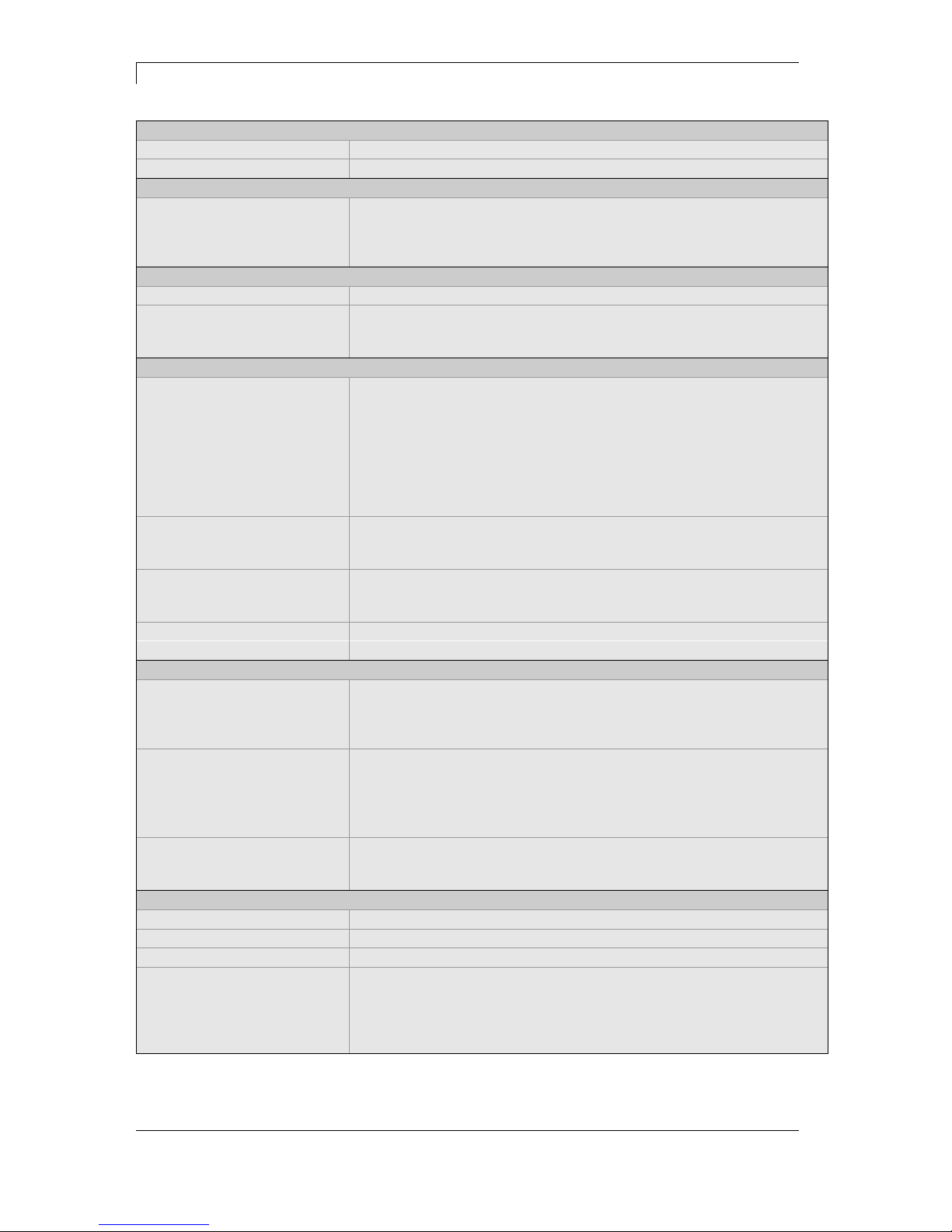
DuoPrint 107/12 DuoPrint 160/12
Print Resolution 305 dpi 305 dpi
Max. Print Speed 150 mm/s 120 mm/s
Print Width 106,6 mm 160 mm
Passage Width 116 mm 176 mm
Printhead Corner Type Corner Type
Labels
Labels/Continuous Material Paper, Cardboard, Textile, Synthetics
Max. Material Weight 220 g/m² (higher on demand)
Min. Label Width 15 mm 50 mm
Min. Label Height 25 mm 25 mm
Max. Label Height 1200 mm / 1100 mm (Option)
(higher on demand)
800 mm / 700 mm (Option)
(higher on demand)
Max. Roll Diameter External unwinder: 300 mm
External rewinder: 300 mm (Option)
Core Diameter 40 mm / 75 mm (Option) 40 mm / 75 mm (Option)
Winding Outside or inside Outside or inside
Label Sensor Transmission + Reflexion from below
Transfer Ribbon
Ink Outside or inside Outside or inside
Max. Roll Diameter Ø 90 mm Ø 90 mm
Core Diameter 25,4 mm / 1″ 25,4 mm / 1″
Max. Length 450 m 450 m
Max. Width 110 mm 163 mm
Dimensions (mm)
Width x Height x Depth 275 x 380 x 475 335 x 380 x 475
Weight ca. 22 kg ca. 27 kg
Dimensions (mm) with option external rewinder
Width x Height x Depth 275 x 410 x 825 335 x 410 x 825
Weight ca. 24,5 kg ca. 29,8 kg
Electronics
Processor High Speed 32 Bit
RAM 16 MB / 64 MB (on demand)
Slot For Compact Flash carte type I
Battery Cache For Real-Time clock (storage of data with shut-down)
Warning Signal Acoustic signal when error
Interfaces
Serial RS-232C (up to 115200 Baud)
Parallel Centronics (SPP)
USB 2.0 High Speed Slave
Ethernet 10/100 Base T, LPD, RawIP-Printing, DHCP, HTTP, FTP
2 x USB Master Connection for external USB keyboard and memory stick
Operation Data
Power Supply 110 … 230 V / 50 … 60 Hz
Max. Power Consumption 600 VA
Nominal Current 230 V - 1,5 A / 110 V - 3 A
Fuse Values 230 V - 3,15 A / 110 V - 5 A
Operating Temperature 5 … 35 °C
Max. Humidity 80% (not condensing)
Page 20
Technical Data DuoPrint Series
20 Operating Manual 10.15
Operation Panel
Keys Test print, function menu, quantity, CF Card, feed, enter, 4 x cursor
LCD Display Graphic display 132 x 64 Pixel - white backlight
Settings
Date, time, shift times
11 language settings (others on demand)
Label and device parameters, interfaces, password protection,
variables
Monitoring
Stop printing if End of ribbon / end of labels / printhead open
Status report Extensive status print with information about settings e.g. print length
counter, runtime counter, photocell interface and network parameters
Printout of all internal fonts and all supported bar codes
Fonts
Font types 6 Bitmap fonts
8 Vector fonts/TrueType fonts
6 proportional fonts
Other fonts on demand
Character sets Windows 1250 up to1257, DOS 437, 850, 852, 857
All West and East European Latin, Cyrillic, Greek and Arabic (option)
characters are supported
Other character sets on demand
Bitmap fonts Size in width and height 0,8 5,6
Zoom 2 … 9
Orientation 0°, 90°, 180°, 270°
Vector fonts/TrueType fonts Size in width and height 1 … 99 mm
Variable zoom
Orientation 0°, 90°, 180°, 270°
Font attributes Depending on character font - bold, Italic, Inverse, Vertical
Font width Variable
Bar Codes
1D bar codes CODABAR, Code 128, Code 2/5 interleaved, Code 39, Code 39
extended, Code 93, EAN 13, EAN 8, EAN ADD ON, GS1-128,
Identcode, ITF 14, Leitcode, Pharmacode, PZN 7 Code, PZN 8 Code,
UPC-A, UPC-E
2D bar codes Aztec Code, CODABLOCK F, DataMatrix, GS1 DataMatrix,
MAXICODE, PDF 417, QR Code
Composite bar codes GS1 DataBar Expanded, GS1 DataBar Limited, GS1 DataBar
Omnidirectional, GS1 DataBar Stacked, GS1 DataBar Stacked
Omnidirectional, GS1 DataBar Truncated
All bar codes are variable in height, module width and ratio.
Orientation 0°, 90 °, 180°, 270°.
Optionally with check digit and human readable line.
Software
Configuration ConfigTool
Process control NiceLabel
Label software Labelstar Office Lite, Labelstar Office
Windows driver Windows XP® 32/64 Bit, Windows Vista® 32/64 Bit
Windows 7® 32/64 Bit, Windows 8® 32/64 Bit
Windows 8.1® 32/64 Bit, Windows Server 2003® (R2) 32/64 Bit
Windows Server 2008® 32/64 Bit, Windows Server 2008® (R2) 64 Bit
Windows Server 2012® 64 Bit, Windows Server 2012® (R2) 64 Bit
Technical modifications are subject to change.
Page 21

DuoPrint Series Technical Data
10.15 Operating Manual 21
4.1 Accessories
Tear-off edge
Real time clock with printout date and time
Automatic daylight saving time
Storage of data with shut-down
Variables: link field, counter, date/time, calculation and shift
variable, CF data
Thermal transfer version
USB host for connection of an external USB keyboard and an
USB memory stick
Ethernet interface
Label photocell
(transmission and reflexion from below)
Compact Flash card slot
Windows printer driver on CD ROM
External rewinder PR 12 / PR 17
(max. outer diameter 300 mm)
External unwinder PA 80 / P 81
(max. outer diameter 300 mm)
Dispenser I/O
Connection set
Standard Equipment
Optional Equipment
Page 22
Technical Data DuoPrint Series
22 Operating Manual 10.15
4.2 Control inputs and outputs
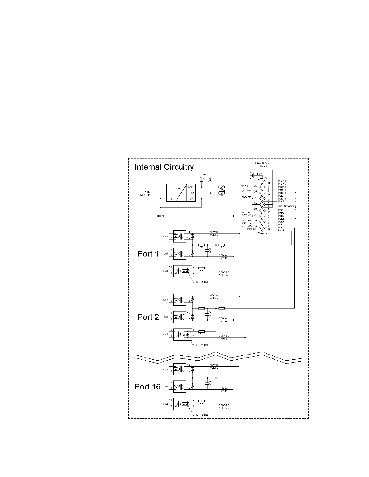
By means of a maximum of 16 control inputs and outputs which, in the
following, are also referred to as ports, different functions of the printer
system can be triggered and operating states can be displayed.
The ports are provided by means of a D-Sub bushing (26pin HD) at
the rear panel of the printer system and are galvanically isolated from
protective earth (PE) by means of an optocoupler semi-conductor
route.
Each port can be configured as input and as output. This function
however, is predefined in the printer software and cannot be changed
by the user.
The following parameters can be changed and set by using the menu:
debounce times and high or low active.
Figure 2
Printer, internal
circuitry
Page 23
DuoPrint Series Technical Data
10.15 Operating Manual 23
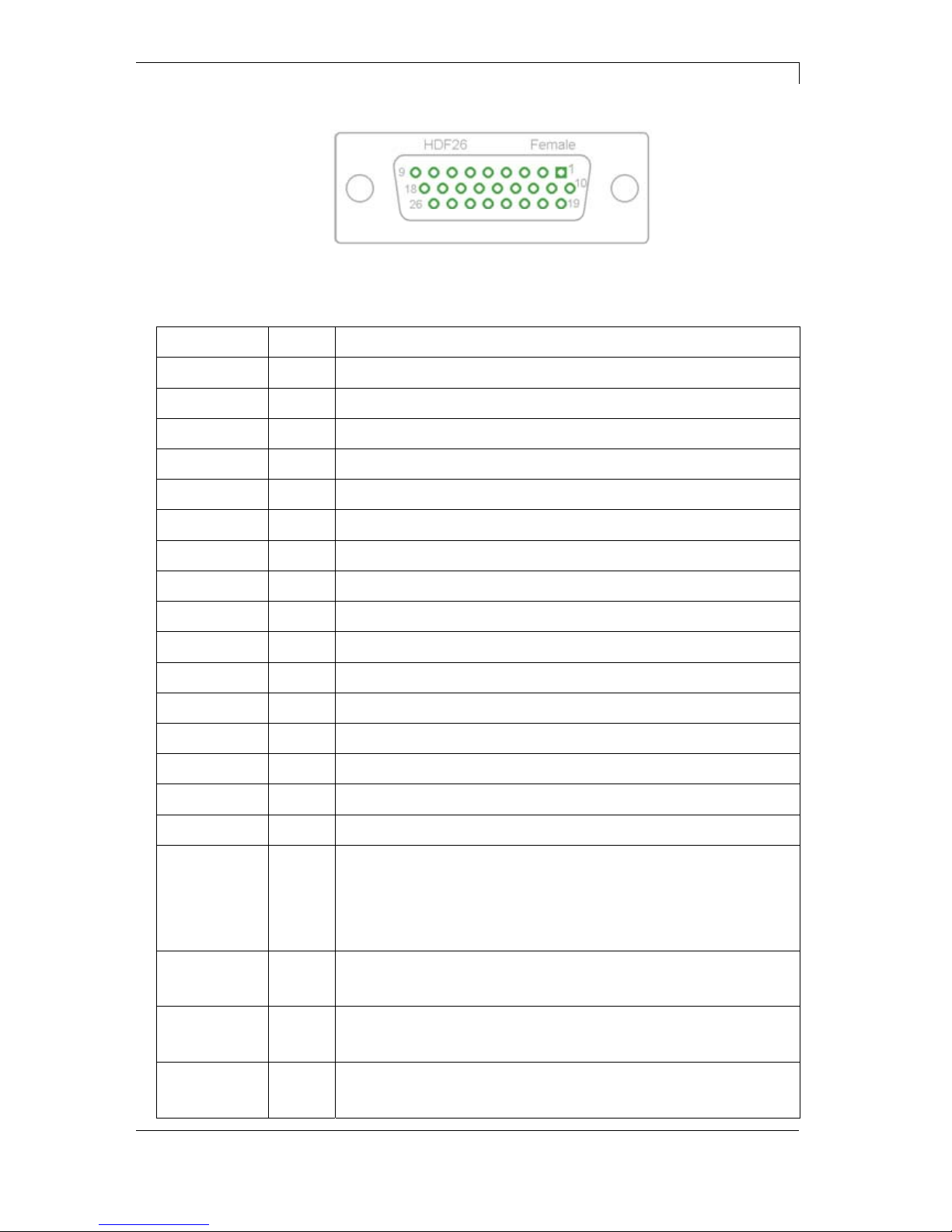
Figure 3
Port 1 to Port 16 = Assignment for I/O Profile 'Std_Label'
Identification Pin Description / Function
Port 1 10 Print start (Input)
Port 2 1 No function
Port 3 11 Counter Reset (Input)
Port 4 2 No function
Port 5 12 Reset error (Input)
Port 6 3 Terminate waiting state (Input)
Port 7 13 No function
Port 8 4 No function
Port 9 15 Error (Output)
Port 10 6 Print order activ (Output)
Port 11 16 Waiting state (Output)
Port 12 7 Single print (Output)
Port 13 17 Ready (Output)
Port 14 8 No function
Port 15 18 No function
Port 16 9 Forerun active (Output)
COM/VDC
for Inputs
19 Common reference potential of all control inputs. 'COM/VDC for
Inputs' is usually connected with the (-) terminal of the control voltage
and the control inputs are switched to active (+).
By means of the option '2nd LED', 'COM/VDC for Inputs' can
optionally be connected with the (+) terminal of the control voltage.
Then, the control inputs are switched to active (-).
VDC for
Outputs
20 Common supply connection of all control outputs. 'VDC for Outputs'
must be connected with the (+) terminal of the control voltage.
Never leave 'VDC for Outputs' open even if no output is used.
COM for
Outputs
5,14
21,22
Common reference potential of all control outputs. 'COM for Outputs'
must be connected with the (-) terminal of the control voltage.
Never leave 'COM for Outputs' open even if no output is used.
GND-PE 23,24 'GND-PE' is the reference potential of the '+5 VDC EXT' and '+24
VDC EXT' voltages provided by the printer system.
'GND-PE' is printer internally connected with protective earth (PE).
Configuration of
D-Sub socket
Page 24
Technical Data DuoPrint Series
24 Operating Manual 10.15
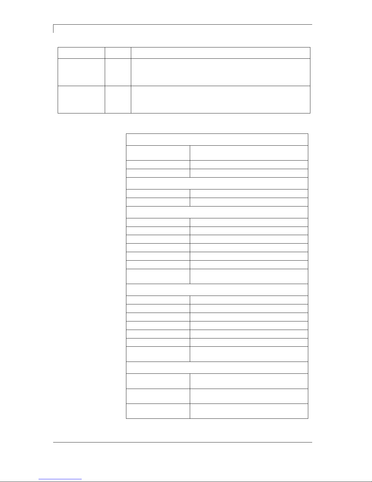
Identification Pin Description / Function
+ 5 VDC
EXT
25 5 Volt DC output for external use. Max. 1 A.
This voltage is provided from direct print module and can be used
e.g. as control voltage. Never apply any external voltage to this
output.
+ 24 VDC
EXT
26 24 Volt DC output for external use. Max. 1 A.
This voltage is provided from direct print module and can be used
e.g. as control voltage. Never apply any external voltage to this
output.
Plug Connector
Type D-Sub connector High Density
26-pin. / connector
Manufacturer W+P-Products
Reference number 110-26-2-1-20
Output Voltages (connected with GND-PE)
+ 24 V / 1 A Fuse: Polyswitch / 30 V / 1 A
+ 5 V / 1 A Fuse: Polyswitch / 30 V / 1 A
Port 1 - 15
Input
Tension 5 VDC … 24 VDC
Impedance 47Ω + (100nF || 10 kΩ)
Output
Tension 5 VDC … 24 VDC
Impedance 47Ω + (100nF || 10 kΩ || 47Ω)
Current max. High +15 mA
Low -15 mA
Port 16
Input
Tension 5 VDC … 24 VDC
Impedance 100nF || 10 kΩ
Output
Tension 5 VDC … 24 VDC
Impedance 100nF || 10 kΩ
Current max. High +500 mA (Darlington BCP56-16)
Low - 500 mA (Darlington BCP56-16)
Optocoupler
Output TCMT4106, CTR 100% - 300%, Vishay or
TLP281-4(GB), CTR 100% - 600%, Toshiba
Input TCMT4106, CTR 100% - 300%, Vishay or
TLP281-4(GB), CTR 100% - 600%, Toshiba
Input
Option 2nd LED
TCMT4600, CTR 80% - 300%, Vishay or
TLP280-4, CTR 33% - 300%, Toshiba
Technical data
Page 25
DuoPrint Series Technical Data
10.15 Operating Manual 25
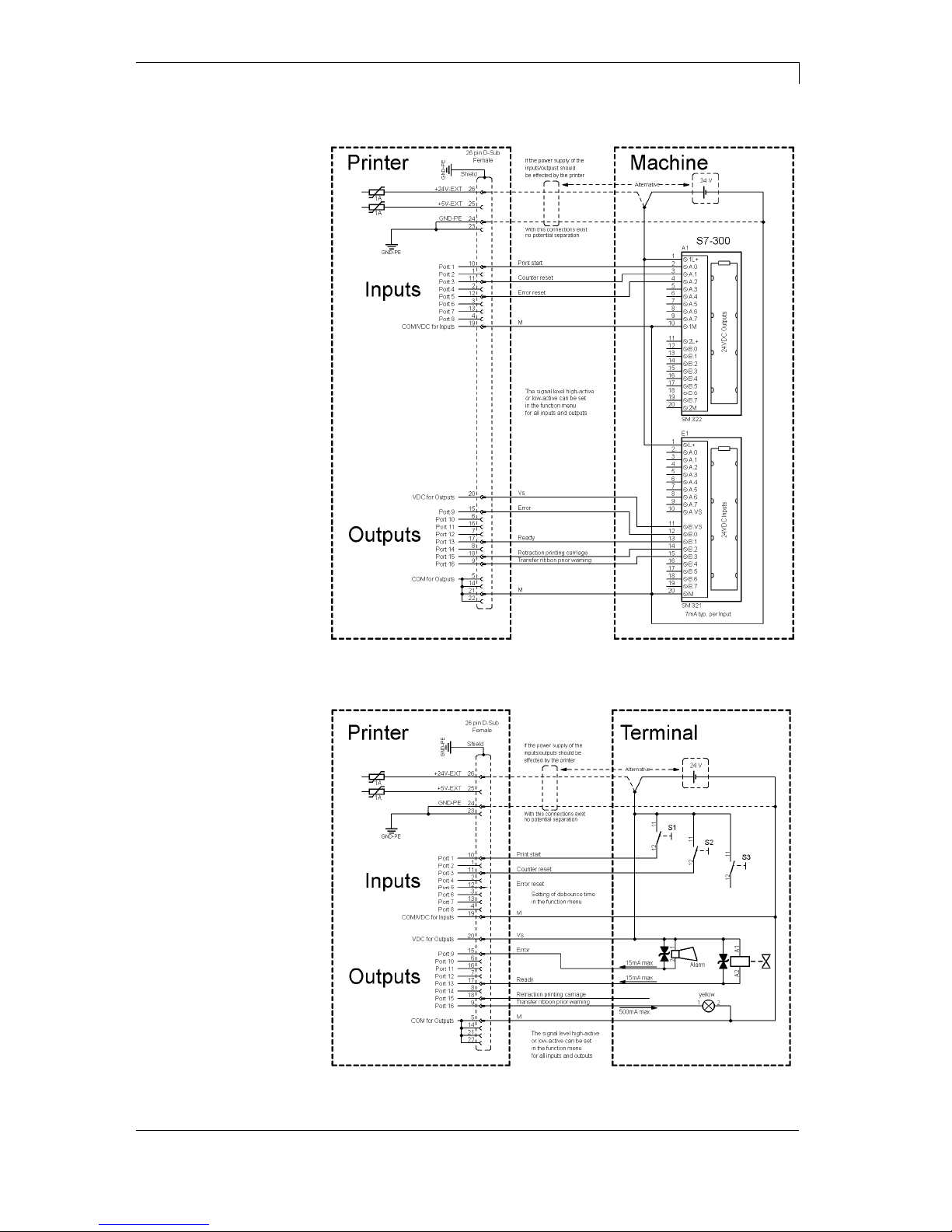
Device connection to a machine with S7-300 SPS.
Figure 4
Device connection to a operating panel.
Figure 5
Example 1
Example 2
Page 26
Technical Data DuoPrint Series
26 Operating Manual 10.15
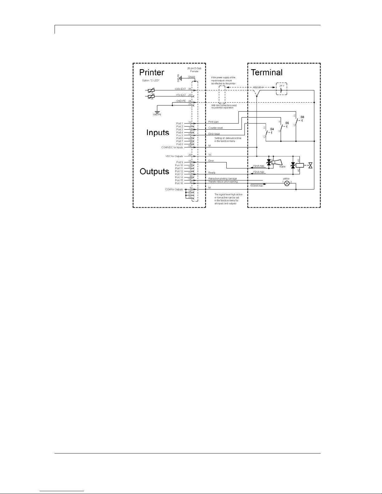
Device connection version if 'Option: 2. LED'.
Figure 6
When connecting a reed contact with a control input, the contact must
have a switching capacity of min. 1 A in order to prevent the contact
from sticking due to the inrush current. As an alternative, a suitable
resistor can be connected in series.
If one of the printer’s internal voltages '+5 VDC EXT' or '+24 VDC
EXT' is used, an external fuse e.g. 0.5 AF, should be additionally
installed to protect the printer electronics.
In the event of an inductive load, an antiparallel connected diode, for
instance, must be used to discharge the induction energy.
In order to minimise the influence of leakage currents at control
outputs, a resistor must, depending on what is connected, be installed
in parallel with the load.
In order to avoid any damages to the printing system, the max. output
currents must not be exceeded or outputs shorted.
Example 3
Precautions
Page 27
DuoPrint Series Technical Data
10.15 Operating Manual 27
4.3 Plug & Play
Plug & Play capable printers can be recognised automatically at
parallel ports, USB-IEEE 1394- or infra-red connections but the last
both are not important for our printers.
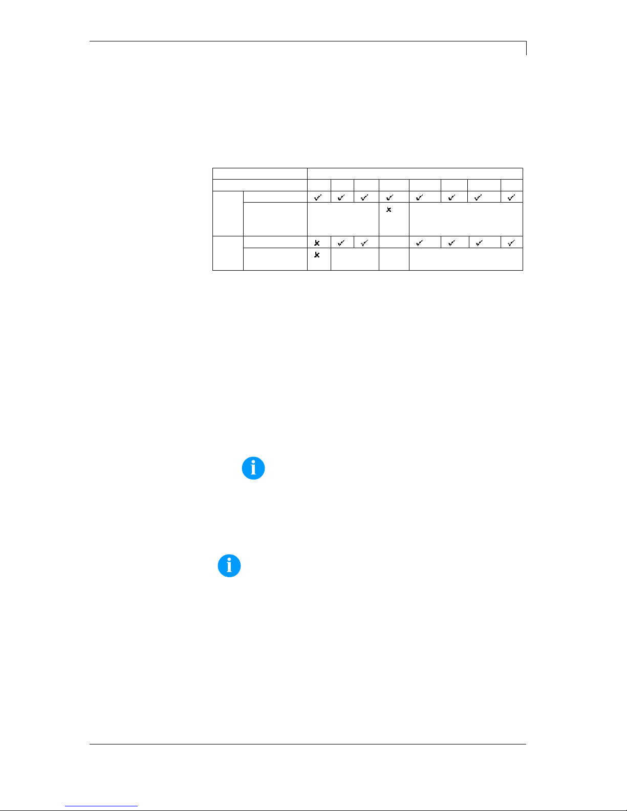
The following table shows the Plug & Play capability of the different
operating systems.
Interface Windows
95 98 Me NT4 2000 XP Vista 7
LPT
Support
Recognition
by
Boot
Procedure,
Dev. Manager
Installation
USB
Support
s.b.
Recognition
by
Hot Plug
& Play
s.b. Hot Plug & Play
The table above shows that USB provides the recognition during the
connection in current operating mode, the so-called Hot-Plug & Play.
Depending on the operating system, for the parallel interface the
different possibilities are given:
Windows 95 / 98 / Me
Printers can be recognized during the starting procedure of
Windows or by the Search for new hardware by means of the
hardware wizard.
Windows 2000 / XP / Vista / 7
Printers can be recognized during the starting procedure of
Windows or by the Search for new hardware by means of the
hardware wizard or if the option 'Automatic recognition and
installation of Plug & Play printer' and/or 'Search automatically for
new hardware components and install' is activated.
NOTICE!
If a driver is installed outside of the Plug & Play
recognition, Windows reports at each restart that a new
printer was found. In this case, the driver is to be
installed anew by the Wizard. If the driver is certified for
Windows, the reinstallation is executed automatically.
NOTICE!
Windows NT 4.0 does not support USB devices. However,
some distributors offer drivers that support USB (without Plug
& Play). Such a driver which suits to our printer is offered from
BSQUARE. For more information, visit their web site:
www.bsquare.com or contact
BSQUARE Headquarters (USA)
888-820-4500
sales @bsquare.com
BSQUARE (Europe)
+49 (811) 600 59-0
[email protected]
Page 28

Page 29

DuoPrint Series Installation
10.15 Operating Manual 29
5 Installation
Lift the label printer out of the box.
Check the label printer for transport damages.
Check delivery for completeness.
Label Printer.
Power Cable.
Empty core, mounted on transfer ribbon rewinder.
Tear-off edge.
Rewinder (optional).
Unwinder (optional).
Documentation.
Printer driver on CD ROM.
NOTICE!
Retain original packaging for subsequent transport.
5.1 Setting up the Label Printer
CAUTION!
The label printer and the print media can be damaged by
moisture and water.
Set up the label printer only in a dry place protected
from sprayed water.
Set up label printer on a level, vibration-free and air draught-free
surface.
Open cover of label printer.
Remove foam transportation safeguards near the printhead.
Unpack the
label printer
Scope of delivery
Page 30
Installation DuoPrint Series
30 Operating Manual 10.15
5.2 Connecting the Label Printer
The label printer is equipped with a versatile power supply unit. The
device may be operated with a mains voltage of 110-230V / 50-60 Hz
without any adjustments or modifications.
CAUTION!
The label printer can be damaged by undefined switch-on
currents.
Set de power switch to '0' before plugging in the label
printer.
Insert power cable into power connection socket.
Insert plug of power cable into a grounded electrical outlet.
NOTICE!
Insufficient or missing grounding can cause faults during
operation.
Ensure that all computers and connection cables connected to
the label printer are grounded.
Connect label printer to computer or network with a suitable
cable.
5.3 Connector Pin Assignment (Printer Rear)
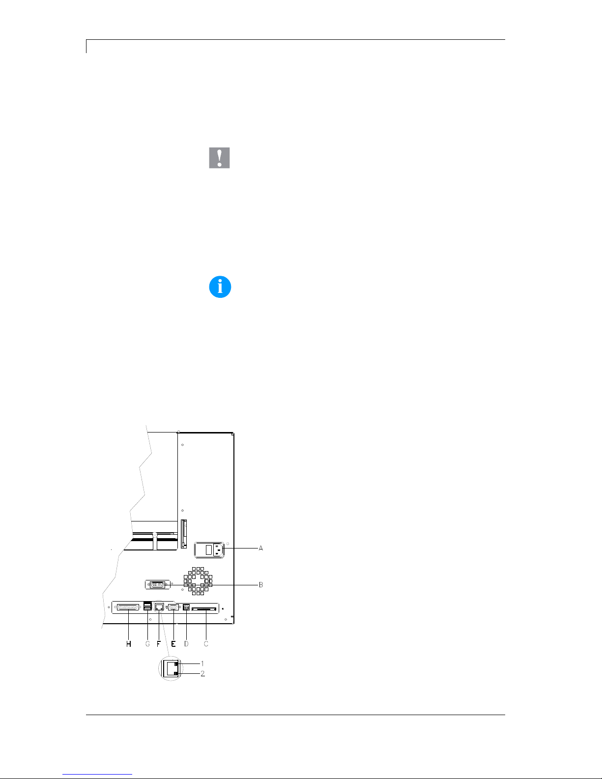
Figure 7
A Power supply
B External Output/Input (Option)
C Compact Flash card slot
D USB interface
E Serial interface RS-232
F Ethernet 10/100 interface
1 = LED orange
Lighting = Connection active
Flashing = Data transfer
Off = No connection
2 = LED green
Lighting: Speed 100 MBit
Off: Speed 10 MBit
G USB host for USB keyboard and
USB memory stick
H Centronics
Connecting to the
power supply
Connecting to a
computer or
computer network
Page 31

DuoPrint Series Installation
10.15 Operating Manual 31
5.4 Start-Up
After all connections are made switch on the label printer.
After switching on the label printer the main menu appears which
shows the printer type, current date and time.
Insert label material and transfer ribbon (see chapter 6. Loading
Media, page 33).
Go to menu Label layout, select menu item Measure label and start
measuring (see chapter 7.4 Label layout, page 42).
Press key
to finish measuring.
NOTICE!
To enable correct measuring, at least two completed labels have
to be passed through (not for continuous labels).
During the measuring procedure of label and gap length small
differences can occur. Therefore the values can be set and
transferred to the printer by means of the label design software as well
as via the printer driver.
Page 32

Page 33
DuoPrint Series Loading Media
10.15 Operating Manual 33
6 Loading Media
6.1 Loading Label Roll
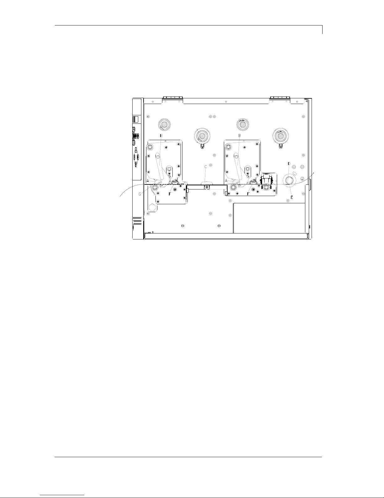
Figure 8
1. Open the printer cover.
2. Open printheads (A) by turning the red pressure levers (B)
anticlockwise.
3. Remove the optional outside label mounting plate from the
unwinder.
4. Load the label roll with inner winding onto the unwinding roll.
5. Attach again the label mounting plate.
6. Lead the label material below the return pulley (D) and the
printheads (A).
Pay attention that the label runs through the photocells (F).
7. In order to move the printheads (A) down, turn the red pressure
levers (B) in clockwise direction until they lock.
8. In front of the first printhead you can see the tear off edge (G)
from which you can rip off labels to the bottom.
9. Enter the offset value in the menu Print settings/Tear-off.
10. Adjust the adjusting ring (E) onto the return pulley (D) and the
label guiding (C) to the width of material.
11. Close the printer cover.
Loading label roll
in tear-off mode
Page 34
Loading Media DuoPrint Series
34 Operating Manual 10.15
6.2 Loading Label Roll with Option PA 8X
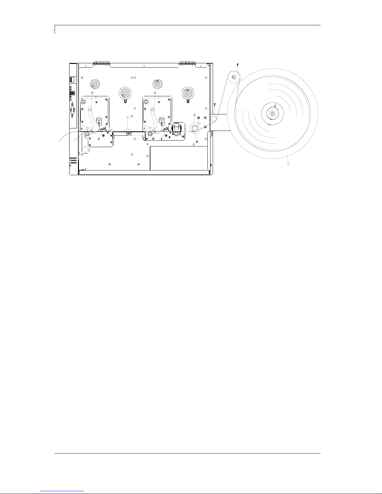
Figure 9
1. Open the printer cover.
2. Insert the CV label unwinding device PA 8X from behind in the
provided cut-out in the rear wall and fasten it using 3 Philips head
screws.
1. Turn the red pressure levers (B) anticlockwise to fold back the
printheads (A).
2. Remove the outer label holding device from the optional
unwinding device (G).
3. Place the label roll with inner winding on the unwinding device
(G).
4. Re-install the outer label holding device.
5. Pass the label material over the dancer roll (F) and under the
deflections shafts (E + D) and the printheads (A).
Ensure that the material runs through the photocells (F).
6. Turn the red pressure levers (B) clockwise until they engage to
fold down the printheads (A).
7. In front of the front printhead, the tear-off edge (J) can be seen.
8. Enter the offset value under the menu item Print
Initialisation/Tear-off Edge.
9. Align the adjusting ring (H) on the deflection shaft (D) and the
label guidance (C) with the material width.
10. Close the printer cover.
Retrofit option CV label
unwinder PA 8X
Load label material
Page 35
DuoPrint Series Loading Media
10.15 Operating Manual 35
6.3 Loading Transfer Ribbon
NOTICE!
For the thermal transfer printing method it is necessary to load a
ribbon, otherwise when using the printer in direct thermal print it
is not necessary to load a ribbon.
The ribbons used in the printer have to be at least the same
width as the print media. In case the ribbon is narrower than the
print media, the printhead is partly unprotected and this could
lead to early wear and tear.
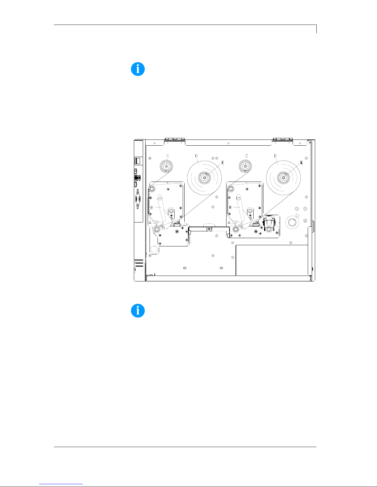
Figure 10
NOTICE!
Before a new transfer ribbon roll is loaded, the printhead must be
cleaned using printhead and roller cleaner (97.20.002).
For more information, see page 71.
The handling instructions for the use of Isopropanol (IPA) must
be observed. In the case of skin or eye contact, immediately
wash off the fluid thoroughly with running water. If the irritation
persists, consult a doctor. Ensure good ventilation.
1. Open the printer cover.
2. Open printheads (A) by turning the red pressure levers (B)
anticlockwise.
3. Load the transfer ribbon rolls (D) with outer winding onto the
unwinding rolls (E).
Page 36

Loading Media DuoPrint Series
36 Operating Manual 10.15
4. Place empty ribbon rolls onto the rewinding rolls (C) and lead the
transfer ribbon below the printheads (A).
5. Fix the beginnings of each transfer ribbon with an adhesive tape
in rotating direction at the empty roll of the rewinding
rolls (C).
Pay attention to the rotation direction of transfer ribbon rewinder
anticlockwise.
6. In order to move the printheads (A) down, turn the red pressure
levers (B) in clockwise direction until they lock.
7. Close the printer cover.
NOTICE!
As for the electrostatic unloading the thin coating of the thermal
printhead or other electronic parts can be damaged, the transfer
ribbon should be antistatic.
The use of wrong materials can lead to printer malfunctions and
the guarantee can expire.
Page 37
DuoPrint Series Function Menu
10.15 Operating Manual 37
7 Function Menu
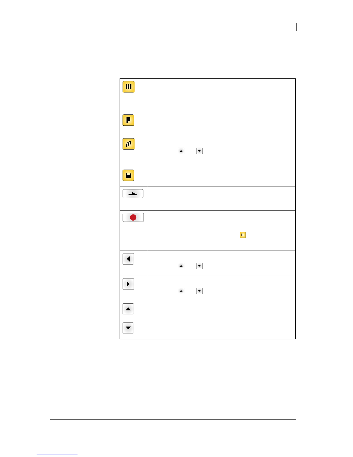
7.1 Keyboard
Back to the main menu.
Start a test print.
Delete a stopped print order.
Change to the function menu.
In function menu: one menu item back.
Change to the quantity (number of pieces) menu.
Press keys
and to select the number of labels that
should be printed.
Change to the menu of the Compact Flash card.
In main menu: feed of one label.
In function menu: skip to the next menu item.
Confirm settings and modifications.
Stop and continue current print orders.
Delete a stopped print order with key
. No further label of
the print order is printed.
Return to the previous input field.
Press keys
and to change the values.
Skip to the next input field.
Press keys
and to change the values.
Increase figure at the cursor position.
Decrease figure at the cursor position.
Page 38
Function Menu DuoPrint Series
38 Operating Manual 10.15
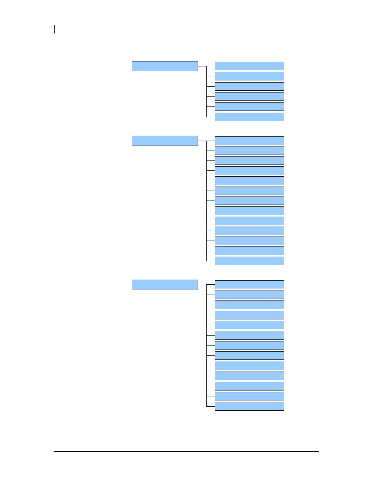
7.2 Menu Structure
Speed
Contrast
Ribbon control
Y offset
X offset
Tear-off offset
Print Settings
Label length
Gap length
Column printing
Measure label
Label type
Material selection
Photocell
Scan position
Label error length
Synchronisation
Flip label
Rotate label
Alignment
Label Layout
Codepage
External parameters
Buzzer
Display
Language
Keyboard
Customized entry
Password
Standard label
Device Settings
Colour processing
Backfeed
CMI length
Synchronisation at switch on
Page 39
DuoPrint Series Function Menu
10.15 Operating Manual 39
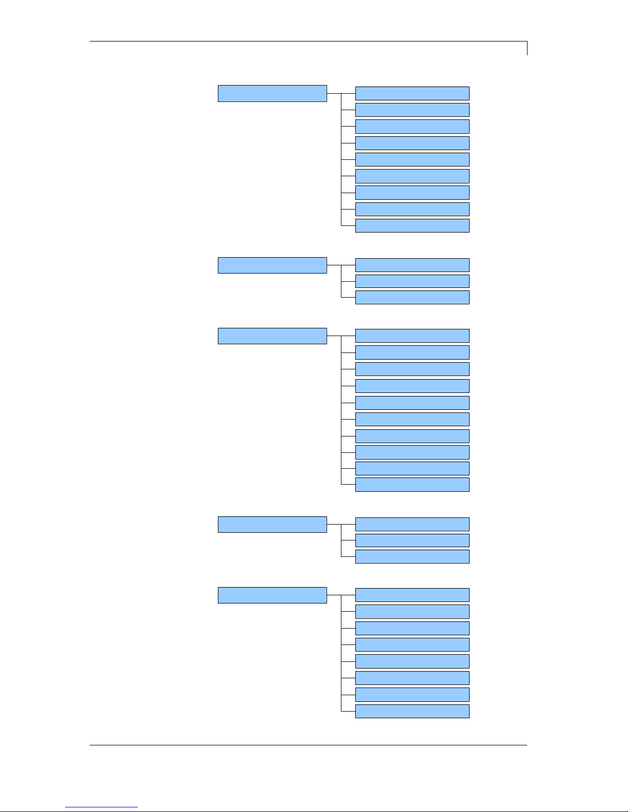
Operating modes
I/O port 1-8
I/O port 9-16
Debounce
Start signal delay
Dispenser I/O (Option)
I/O protocol
Save signal
I/O profile
Photocell level
Ribbon save mode
Material Savings
Label save mode
Auto feed delay
IP address
Netmask
Standard Gateway
Speed/Duplex
DHCP
Printer name
Network
MAC address
Net password
HTTP password enable
Telnet password enable
Port
Operating modes
Remote Console
Interval
COM1
Baud
Parity
Data bits
Stop bit
Interface
Start sign
Stop sign
Port test
Page 40
Function Menu DuoPrint Series
40 Operating Manual 10.15
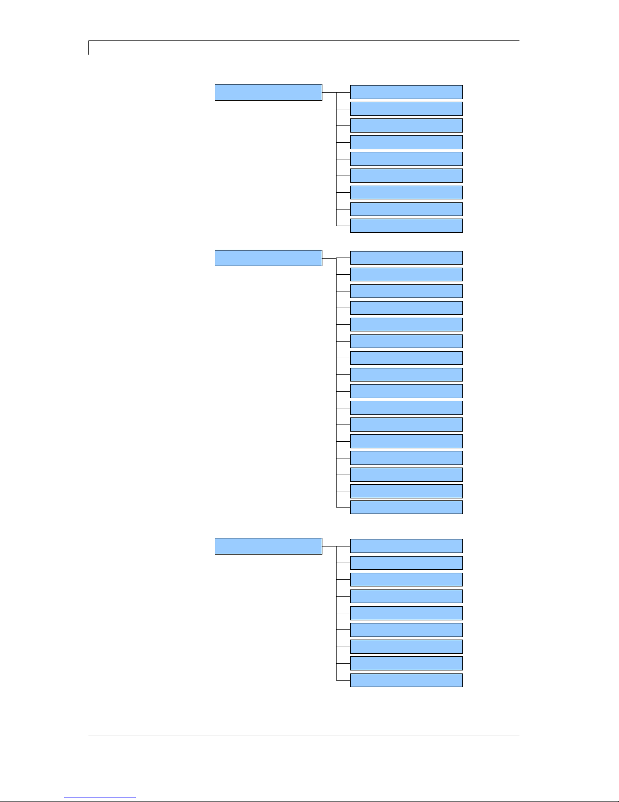
Set date/time
Summertime
Start of summertime - format
Start of summertime - date
Start of summertime - time
End of summertime - format
End of summertime - date
End of summertime - time
Time shifting
Date/Time
Label parameters
Photocell settings
Photocell/sensors
Paper counter
Heater resistance
Printhead temperature
Motor ramp
Input
Service Functions
Output
Printhead 2 Offset
Online/Offline
Zero point adjustment
Print length +/-
Setting mode
Print examples
Internal
Load layout
Change directory
Load file
Save layout
Save configuration
Delete file
Formatting
CF Card / USB Stick
Copying
Firmware update
Page 41
DuoPrint Series Function Menu
10.15 Operating Manual 41
7.3 Print settings
Switch on the label printer and the display shows the main menu.
Press key
to access the function menu.
Press key
to select the menu Print settings.
Indication of print speed in mm/s (see chapter Technical Data,
page 19). The print speed can be determined for each print order
anew.
The setting of print speed affects also the test prints.
Indication of value to set the print intensity when using different
materials, print speeds or printing contents.
The contrast can be set for both printheads.
Value range: 10% … 200 %.
Step size: 10%.
Press key
to arrive the next menu item.
Examination if the transfer ribbon roll is to end or if the ribbon was torn
at the unwinding roll.
Off: The ribbon control is deselected, i.e. the printer continues without
an error message.
On: The ribbon control is selected, i.e. the current print order is
interrupted and an Error Message appears at the printer display.
Strong sensibility: The printer reacts immediately to the end of the
transfer ribbon.
Weak sensibility: The printer reacts at approx. 1/3 more slowly to the
end of the transfer ribbon.
Press key
to arrive the next menu item.
Indication of initial point displacement in mm.
Displacement of the complete print in paper direction. With positive
values the print in paper direction starts later.
The value is set for both printheads together.
Value range: −30.0 … +90.0.
Press key
to arrive the next menu item.
Displacement of the complete print transverse to the paper direction.
The displacement is possible only up to the edges of the printing zone
and is determined by the width of the focal line in printhead.
The value is set for both printheads together.
Value range: −90.0 … +90.0.
Press key
to arrive the next menu item.
Indication of value to which the last label of a print order is moved
forward and is moved back to the beginning of label at a new print
start. Labels can be torn off after terminating the print order without a
label loss by tearing up.
Default value: 12 mm.
Value range: 0 … 50.0 mm.
Speed
Contrast
Ribbon control
Y displacement
X displacement
Tear-off
Page 42
Function Menu DuoPrint Series
42 Operating Manual 10.15
7.4 Label layout
Switch on the label printer and the display shows the main menu.
Press key
to access the function menu.
Press key
as long as you arrive the Label layout menu.
Press key
to select the menu.
Indication of label length in mm
(see chapter Technical Data, page 19).
Indication of distance between two labels in mm
(not for continuous labels).
Minimum value: 1 mm.
Press key
to arrive the next menu item.
Indication of width of one label as well as how many labels are placed
side by side (see chapter 11.1 Column Printing, page 87).
Press key
to arrive the next menu item.
Press key
to start measuring. The printer stops automatically
after termination of measuring. The determined values are displayed
and saved.
Press key
to arrive the next menu item.
Generally adhesive labels are set. Press key
to select continuous
labels. If the menu item Label length/Gap length contains a gap value,
this value is added to the label length..
Press key
to arrive the next menu item.
Selection of the used label and transfer ribbon material.
Press key
to arrive the next menu item.
Selection of the used photocell. The selection of one of the following
photocell types is possible:
Transmission photocell normal and inverse, reflexion photocell normal
and inverse (see chapter 11.3 Photocells, page 90).
Entry of percental label length by that the label end is searched.
Marks onto the label can be skipped.
Label length
Gap length
Column printing
Measure label
Label type
Material selection
Photocell
Scan position (SP)
Page 43

DuoPrint Series Function Menu
10.15 Operating Manual 43
Press key
to arrive the next menu item.
In case an error occurs, indication after how many mm a message
appears in the display.
Value range:1 mm … 999 mm.
On: If a label is missed on the liner an error message is displayed.
Off: Missing labels are ignored, i.e. it is printed into the gap.
Press key
to arrive the next menu item.
The axis of reflection is in the middle of the label. If the label width
was not transferred to the printer, automatically the default label width
i.e. the width of the printhead is used. It is recommended to use labels
with the same width as the printhead. Otherwise this can cause
problems in positioning.
Press key
to arrive the next menu item.
According to standard the label is printed ahead with a rotation of 0°. If
the function is activated, the label is rotated by 180° and printed in
reading direction.
Press key
to arrive the next menu item.
The adjustment of label is effected only after Flip/Rotate label, i.e. the
adjustment is independent of the functions Flip label and Rotate label.
Left: The label is aligned at the left-most position of printhead.
Centre: The label is aligned at central point of printhead.
Right: The label is aligned at right-most position of printhead.
Label error length
Synchronisation
Flip label
Rotate label
Alignment
Page 44
Function Menu DuoPrint Series
44 Operating Manual 10.15
7.5 Device settings
Switch on the label printer and the display shows the main menu.
Press key
to access the function menu.
Press key
as long as you arrive the Device settings menu.
Press key
to select the menu.
Indication of the font used in the printer. The following possibilities are
available:
Codepage 1252 West European (former ANSI)
Codepage 437 English
Codepage 850 Western European
Codepage 852 Slavic
Codepage 857 Turkish
Codepage 1250 Central and East European
Codepage 1251 Cyrillic
Codepage 1253 Greek
Codepage 1254 Turkish
Codepage 1257 Baltic
WGL4
Please find the tables referring to the above mentionned character
sets on www.carl-valentin.de/Downloads.
Press key
to arrive the next menu item.
Label dimension only: The parameters for label length, gap length
and label width can be transferred to the printer. All other parameter
settings are to be made directly at the printer.
On: Sending parameters such as print speed and contrast via our
label creation software to the printer. Parameters which are set
directly at the printer before are no longer considered.
Off: Only settings made directly at the printer are considered.
Press key
to arrive the next menu item.
On: An acoustic signal is audible when pressing a key.
On: Value range: 1 … 7.
Off: No signal is audible.
Setting of display contrast.
Value range: 35 … 85.
Press key
to arrive the next menu item.
Selection of language in which you want to display the text in the
printer display.
At the moment the following languages are available: German,
English, French, Spanish, Portuguese, Dutch, Italian, Danish, Finnish,
Polish, Czech and Russian.
Press key
to arrive the next menu item.
Selection of region for the desired keyboard layout.
The following possibilities are available: Germany, England, France,
Greece, Spain, Sweden and US.
Codepage
External parameters
Buzzer
Display
Printer language
Keyboard layout
Page 45
DuoPrint Series Function Menu
10.15 Operating Manual 45
Press key
to arrive the next menu item.
On: The question referring the customized variable appears once
before the print start at the display.
Auto: The question referring the customized variable appears after
every printed layouts.
Off: No question appears at the display. In this case the stored default
value is printed.
Press key
to arrive the next menu item.
On: The print is effected on both printheads corresponding to the
transferred field attributs.
Off, print to PH1: The print is effected at the front printhead.
Off, print to PH2: The print is effected at the rear printhead.
At both operating modes the field attributs are ignored and all fields
are printed on the set printhead.
Press key
to arrive the next menu item.
The backfeed was optimised in the operating modes dispenser
(optional) and tear off. Now, when driving into the offset, the following
label is 'pre-printed' if possible and therefore the backfeed of label is
no necessary and time can be saved.
Press key
to arrive the next menu item.
If the print is stopped at the rear printhead it could come to a small
interruption in the printout. This is shown as a fine white line onto the
label. In order to avoid this matter a value for the minimal retraction
(0 – 1 mm) can be set. At this value the label material is retracted. At
the next print start the free range is overprinted.
Press key
to arrive the next menu item.
By a password several functions can be blocked, so the user cannot
work with them. There are several applications in which the use of
password protection makes sense (see chapter 11.2 Password
Protection, page 88).
Press key
to arrive the next menu item.
On: If a print order is started without previous definition of label, the
standard label is printed.
Off: If a print order is started without previous definition of label, an
error message appears in the display.
Customized entry
Colour processing
Backfeed
CMI length
Password
Standard label
Page 46

Function Menu DuoPrint Series
46 Operating Manual 10.15
7.6 Dispenser I/O (option)
Switch on the label printer and the display shows the main menu.
Press key
to access the function menu.
Press key
as long as you arrive the Dispenser I/O menu.
Press key
to select the menu.
In the upper line of display, the operating mode can be selected.
Press key
to change to the next operating mode.
Off:
It is printed without the labels are dispensed.
I/O static:
The input signal evaluated, i.e. it is printed as long as the signal
exists. The number of labels which was entered at the print start is
printed.
The set dispenser offset is not taken into consideration.
I/O static continuous:
For description of this operating mode, see I/O static.
Continuous means that it is printed as long as new data is transferred
via interface
The set dispenser offset is not taken into consideration.
I/O dynamic:
The external signal is evaluated dynamically, i.e. is the printer in
'waiting' mode a single label is printed at each signal changing. After
the print the set dispenser offset is executed, i.e. a backfeed is
effected.
I/O dynamic continuous:
For description of this operating mode, see I/O dynamic.
Continuous means that it is printed as long as new data is transferred
via interface.
Operating modes
Page 47

DuoPrint Series Function Menu
10.15 Operating Manual 47
After selection of desired Dispenser I/O operating mode, press key
to select additional parameters.
First value = Indication of the current sensor level. This indication
is for checking purposes and cannot be modified.
Second value = Indication if a label (value = 1) or if no label (value =
0) was found. This indication is for checking
purposes if the set switch level leads to a correct
label recognition.
Third value = Indication of switch level (Default: 1.2).
Fourth value = Transmission power of label sensor [1..255]
Depending on label material (color) the sensor level
can be adapted in order to permit a safe label
recognition (Default: 80).
NOTICE!
The modification of this value is only taken into consideration
for the operating modes Photocell and Photocell continuous.
Press key
to arrive the next menu item.
Definition of port functions. 2 sign show the current setting for each
port.
The first sign specifies the following:
I
= Port operates as Input
O
= Port operates as Output
N
= Port has no function (not defined)
These settings cannot be modified.
The second sign specifies the following:
+
= Active signal level is 'high' (1)
−
= Active signal level is 'low' (0)
x
= Port is deactivated
&
= Function is executed at each change of the signal level
s
= Status can be enquired/influenced
*
by interface
= The internal function of print module is deactivated.
The modification of the signal level is only taken into consideration for
the operating modes I/O static, I/O dynamic, I/O static continuous and
I/O dynamic continuous.
Press key
to arrive the next menu item.
Indication of debounce time of the dispenser input. The setting range
of the debounce time is between 0 and 100 ms.
In case the start signal is not clear then you can debounce the input
by means of this menu item.
*
in connection with Netstar PLUS
Additional parameters
for Dispenser I/O
Dispenser photocell
I/O Port 1-8 and
I/O Port 9-16
Debounce
Page 48
Function Menu DuoPrint Series
48 Operating Manual 10.15
Press key
to arrive the next menu item.
Indication in time per second of the delay for the start signal.
Value range: 0.00 to 9.99.
Press key
to arrive the next menu item.
Indication of interface at which the modifications of input signals (I/O)
are sent.
Press key
to arrive the next menu item.
On: The start signal for the next label can already be released during
printing the current label. The signal is registered from the print
module. The print module starts printing the next label immediately
after finishing the current one. Therefore time can be saved and
performance be increased.
Off: The start signal for the next label can only be released if the
current label is printed to the end and the print module is again in
'waiting' state (output 'ready' set). If the start signal was released
already before, so this is ignored.
Press key
to arrive the next menu item.
Selection of the available configurations Std_Label (factory setting) or
StdFileSetLabel.
The corresponding assignment is indicated on the following page.
1 Print start (Input)
2 No function
3 Counter reset (Input)
4 No function
5 Error reset (Input)
6 No function
7 No function
8 No function
9 Error (Output)
10 Print order active (Output)
11 No function
12 Printing (Output)
13 Ready (Output)
14 No function
15 No function
16 Forerun active (Output)
Start signal delay
I/O protocol
Save signal
I/O Profile
List of registered
functions for
Std_Label
Page 49

DuoPrint Series Function Menu
10.15 Operating Manual 49
1 Print start (Input)
2 Error reset (Input)
3 Number of the file to load Bit 0 (Input)
4 Number of the file to load Bit 1 (Input)
5 Number of the file to load 2 (Input)
6 Number of the file to load 3 (Input)
7 Number of the file to load 4 (Input)
8 Number of the file to load 5 (Input)
9 Error (Output)
10 Print order active (Output)
11 No function
12 Printing (Output)
13 Ready (Output)
14 No function
15 No function
16 Forerun active (Output)
List of registered
functions for
StdFileSetLabel
Page 50
Function Menu DuoPrint Series
50 Operating Manual 10.15
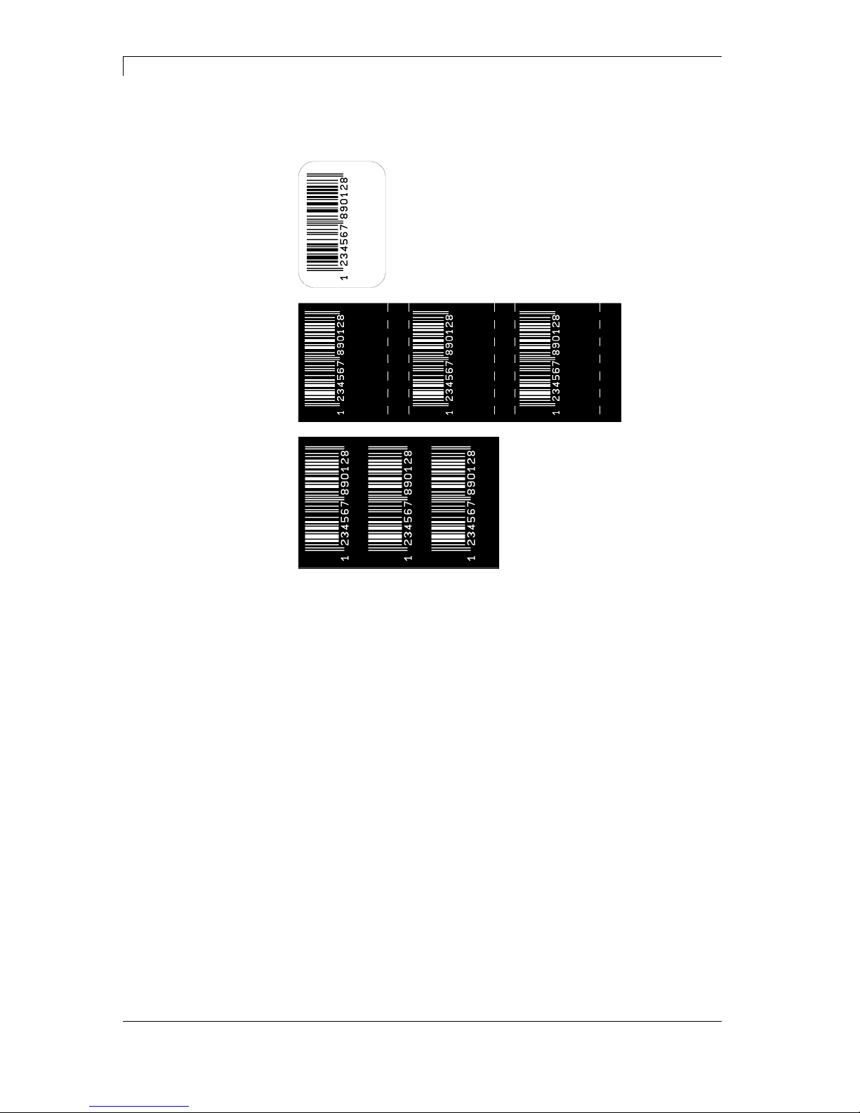
7.7 Material Savings
Ribbon save = maximum exploitation of transfer ribbon
23/1500
23/1500
23/1500
23/1500
23/1500
23/1500
23/1500
In general, the maximum exploitation of the transfer ribbon is achieved
in that the transfer ribbon stops in the event of gaps within the label
and/or the distance between two labels and the printhead folds in, i.e.
is moved upwards. Thus, the transfer ribbon consumption is reduced.
As can be clearly seen in the example provided above, the transfer
ribbon consumption is significantly lower in the ‘standard‘ ribbon save
mode.
In the ‘Off’ ribbon save mode, the printhead is not folded in and, thus,
the transfer ribbon consumption is not reduced.
Label
Transfer gibbo
w/o ribbon save
Transfer ribbon
with ribbon save
Procedure
Page 51
DuoPrint Series Function Menu
10.15 Operating Manual 51
Switch on the label printer and the display shows the main menu.
Press key
to access the function menu.
Press key
as long as you arrive the Ribbon save menu.
Press key
to select the menu.
Press keys
and to select the desired ribbon save mode.
Off
Optimisation off.
Standard
Maximum optimisation performance, i.e. there is no
transfer ribbon loss whilst this setting is used (except
for a safety distance of 1 mm so that the print fields
are not printed into one another).
Settings with which this optimisation can no longer
be achieved are not permitted. This applies in
particular to offset printing which can now only set in
the valid range.
Press key
to arrive the next menu item.
Dialog
The printing process is stopped at a suitable position
and the printer waits for further data. As soon as this
data is transferred to the printer, the printing process
continues.
At the end of a print job, the printer remains in the
above position so that a follow-up print job can be
transferred to the printer without any loss of material.
Press the
key to stop the print job. In doing so,
the remaining labels of the print job are completed.
Blank labels are fed into the printer until the last
completed label has passed the front printhead.
Auto
After an adjustable time which can be set under the
menu item Auto feed delay, the remaining labels
between the two printheads are printed.
Off
The print is only stopped after complete printing of all
labels. Slow data connections or labels with a long
generating time can lead to a loss of material. In the
dispensing modes is this mode activated
automatically.
Ribbon save mode
Label save mode
Page 52
Function Menu DuoPrint Series
52 Operating Manual 10.15
Press key
to arrive the next menu item.
Setting of time after that the remaining labels between the printheads
were automatically printed.
Value range 0 … 255 seconds
7.8 Network
Switch on the label printer and the display shows the main menu.
Press key
to access the function menu.
Press key
as long as you arrive the Network menu.
Press key
to select the menu.
For more information, please see the separate manual.
7.9 Remote console
Switch on the label printer and the display shows the main menu.
Press key
to access the function menu.
Press key
as long as you arrive the Remote console menu.
Press key
to select the menu.
For more information please contact our sales department.
Auto feed delay
Page 53
DuoPrint Series Function Menu
10.15 Operating Manual 53
7.10 Interface
Switch on the label printer and the display shows the main menu.
Press key
to access the function menu.
Press key
as long as you arrive the Interface menu.
Press key
to select the menu.
COM1:
0 - serial interface Off.
1 - serial interface On.
2 - serial Interface On, no error message occurs in case of a
transmission error.
Baud:
Indication of bits which are transferred per second (speed of data
transfer).
Value range: 1200, 2400, 4800, 9600, 19200, 38400, 57600 and
115200.
P = Parity:
N - No parity
E - Even
O - Odd
Please observe that the settings correspond to those of the printer.
D = Data bits:
Setting of data bits.
Value range: 7 or 8 Bits.
S = Stop bits:
Indication of stop bits between bytes.
Value range: 1 or 2 stop bits.
Press key
to arrive the next menu item.
SOH: Start of data transfer block
Hex format 01
ETB: End of data transfer block Hex formal 17
Two different start / en signs can be set. The settings are normally
SOH = 01 HEX and ETB = 17 HEX. Several host computers cannot
process these signs and therefore SOH = 5E HEX and ETB = 5F
cannot be set.
Press key
to arrive the next menu item.
Check whether the data are transferred via the interface.
Press the
and keys to select standard (on). Press the
key and the data sent via any port (COM1, LPT, USB, TCP/IP) is
printed.
COM1 / Baud /
P / D / S
Start sign / End sign
Port test
Page 54
Function Menu DuoPrint Series
54 Operating Manual 10.15
7.11 Date & Time
Switch on the label printer and the display shows the main menu.
Press key
to access the function menu.
Press key
as long as you arrive the Date/Time menu.
Press key
to select the menu.
The upper line of display shows the current date, the second line the
current time. Press keys
to arrive the next input field. Press
keys
and to increase and/or decrease the figures at the cursor
position.
Press key
to arrive the next menu item.
On: Printer automatically adjust clock for daylight saving changes.
Off: Summertime is not automatically recognized and adjusted.
Press key
to arrive the next menu item.
Select the format in which you want to define beginning summertime.
The above example indicates the default setting (European format).
DD = day WW = week WD = weekday
MM = month YY = year next day = only next day is taken
into consideration
Press key
to arrive the next menu item.
By means of this function you can enter the date at which summertime
has to start. This entry refers to the previously selected format.
Example: summertime is automatically adjusted at last Sunday in
March (03).
Press key
to arrive the next menu item.
By means of this function you can define the time when you want to
start summertime.
Press key
to arrive the next menu item.
Select the format in which you want to define end of summertime. The
example above indicates the default setting (European format).
Press key
to arrive the next menu item.
By means of this function you can define the date when you want to
stop summertime. The entry refers to the previously selected format.
Example: summertime is automatically adjusted at last Sunday in
October (10).
Press key
to arrive the next menu item.
By means of this function you can define the time when you want to
stop summertime.
Press key
to arrive the next menu item.
By means of this function you can enter time shifting in hours and
minutes (for automatically adjustment from summer and wintertime).
This entry refers to the currently set printer time.
Setting of
date and time
Summertime
Start of summertime –
Format
Start of summertime –
Date
Start of summertime –
Time
End of summertime –
Format
End of summertime –
Date
End of summertime –
Time
Time shifting
Page 55
DuoPrint Series Function Menu
10.15 Operating Manual 55
7.12 Service Functions
NOTICE!
So that the distributor res. the manufacturer in case of service
can offer fast support the necessary information such as
selected parameters can be taken directly from the service
functions menu of the device.
Switch on the label printer and the display shows the main menu.
Press key
to access the function menu.
Press key
as long as you arrive the Service functions menu.
Press key
to select the menu.
Indication of label parameters in Volt.
A: Indication of minimum value.
B: Indication of difference between minimum and maximum value.
C: Indication of trigger level. The value is ascertained while measuring
and can be changed.
Press key
to arrive the next menu item.
Indication of photocell level of the front printhead.
In case of problems while positioning or measuring of label, levels for
label photocell can be set manually. Make sure that a large hub as
possible (above the label >3 V, above the gap <1 V) is set.
Press key
to arrive the next menu item.
Indication of photocell level of the rear printhead.
In case of problems while positioning or measuring of label, levels for
label photocell can be set manually. Make sure that a large hub as
possible (above the label >3 V, above the gap <1 V) is set.
Press key to arrive the next menu item.
PC1: Indication of label photocell level of the front photocell in Volt.
PC2: Indication of label photocell level of the rear printhead in Volt.
OPC: Indication of ribbon save photocell level in Volt.
TR: Indication of transfer ribbon photocell status
TR: (either 0 or 1).
TR: The first value stands for the front photocell and the second value
TR: for the rear photocell.
H: Indication of printhead position.
H: 0 = printhead down
H: 1 = printhead up
H: The first value stands for the front photocell and the second value
H: for the rear photocell.
Label parameters
Photocell configuration
(front printhead)
Photocell configuration
(rear printhead)
Photocell parameters
Page 56
Function Menu DuoPrint Series
56 Operating Manual 10.15
Press key
to arrive the next menu item.
Setting Mode ON:
The Printheads can be adjusted more easily.
The following parameters are set automatically: continuous labels,
label size = 50 mm. These settings can be changed manually.
The following control functions are desactivated: 'printhead open'
control, transfer ribbon control, label photocell Off (continuous labels).
CAUTION!
Switching off the control functions can lead to uncontrolled
operation of the printer.
The setting mode is only to use for adjusting the
printheads.
Setting Mode OFF:
When switching Off the printer, the setting mode is automatically
deactivated.
Press key
to arrive the next menu item.
D: Indication of printhead attainment in meters.
G: Indication of printer attainment in meters.
Press key
to arrive the next menu item.
To achieve a high print quality, the indicated Ohm value must be set
after an exchange of printhead.
The heater resistance value can be set for both printheads.
Press key
to arrive the next menu item.
Indication of printhead temperature. The printhead temperature
corresponds normally to the room temperature. In case the maximum
printhead temperature is exceeded, the current print order is
interrupted and an error message appears at the printer display.
The printhead temperature is displayed for both printheads.
Press key
to arrive the next menu item.
For setting the automatic offset for the rear printhead in order to
optimise the print image.
X-adjustment:
Adjusting the position of the print image of the rear
printhead (colour component) transversely to the
direction of paper movement.
Y-adjustment:
Adjusting the position of the print image of the rear
printhead in the direction of paper movement.
Any changes to these parameters alter the relative adjustment of the
print contents of the front and rear printheads.
Setting mode
Paper counter
Heater resistance
Printhead temperature
Printhead 2 Offset
Page 57

DuoPrint Series Function Menu
10.15 Operating Manual 57
Press key
to arrive the next menu item.
This function is often used for high printing speed as the tearing of
transfer ribbon can be prevented.
The higher the '++' value is set, the slower the feeding motor is
accelerated.
The smaller the '−−' value is set, the faster the feeding motor is
decelerated.
Press key
to arrive the next menu item.
Settings: Printout of all printer settings such as speed, label and
transfer ribbon material.
Bar codes: Printout of all available bar code types.
Fonts: Printout of all available font types.
Press key
to arrive the next menu item.
Indication of input signal level.
0 = Low
1 = High
Port Function
1 = Print start
2 = Cut
3 = Counter Reset
4 = External synchronisation of label position
5 = No function
6 = No function
7 = No function
8 = No function
Press key
to arrive the next menu item.
Indication of output signal level
0 = Low
1 = High
Port Function
9 = Error
10 = Print order active
11 = No function
12 = Print end
13 = Ready
14 = No function
15 = No function
16 = Forerun active
Press key
to arrive the next menu item.
This function is activated e.g. if the transfer ribbon is to be changed. It
is avoided that a print order is processed although the module is not
ready. If the function is activated then press the key
to change
between Online and Offline mode. The respective state is indicated in
the display.
Standard: Off
Motor Ramp
Print examples
Input
Output
Online / Offline
Page 58
Function Menu DuoPrint Series
58 Operating Manual 10.15
Online: Data can be received by interface. The keys of the foil
keyboard are only active, if you changed in the Offline mode with key
.
Offline: The keys of the foil keyboard are still active but received data
are not processed. If the module is again in Online mode then new
print orders can be again received.
Press key
to arrive the next menu item.
Indication of value in 1/100 mm.
After replacing the printhead - the print cannot be continued at the
same position on the label, the difference can be corrected in printing
direction.
NOTICE!
The value for zero point adjustment is set ex works. After
replacing the printhead, only service personnel are allowed to
set this value anew.
Press key
to arrive the next menu item.
Indication of value in 1/100 mm.
After replacing the printhead - the print cannot be continued at the
same position on the label, the difference can be corrected across the
printing direction.
NOTICE!
The value for zero point adjustment is set ex works. After
replacing the printhead, only service personnel are allowed to
set this value anew.
Press key
to arrive the next menu item.
Indication of print layout correction in percent.
By mechanical influences (e.g. label roll size) the print layout can be
printed increased and reduced to its original size.
Value range: +10.0% … −10.0%
Press key
to arrive the next menu item.
For internal use only.
7.13 Main menu
Switch on the label printer and the display shows the main menu. The
main menu shows information such as printer type, current date and
time, version number of firmware and the used FPGA.
The selected display is shown for a short time, then the indication
returns to the first information.
Press key
to arrive the next information display.
Zero point adjustment
in Y direction
Zero point adjustment
in X direction
Print length +/−
Internal
Page 59
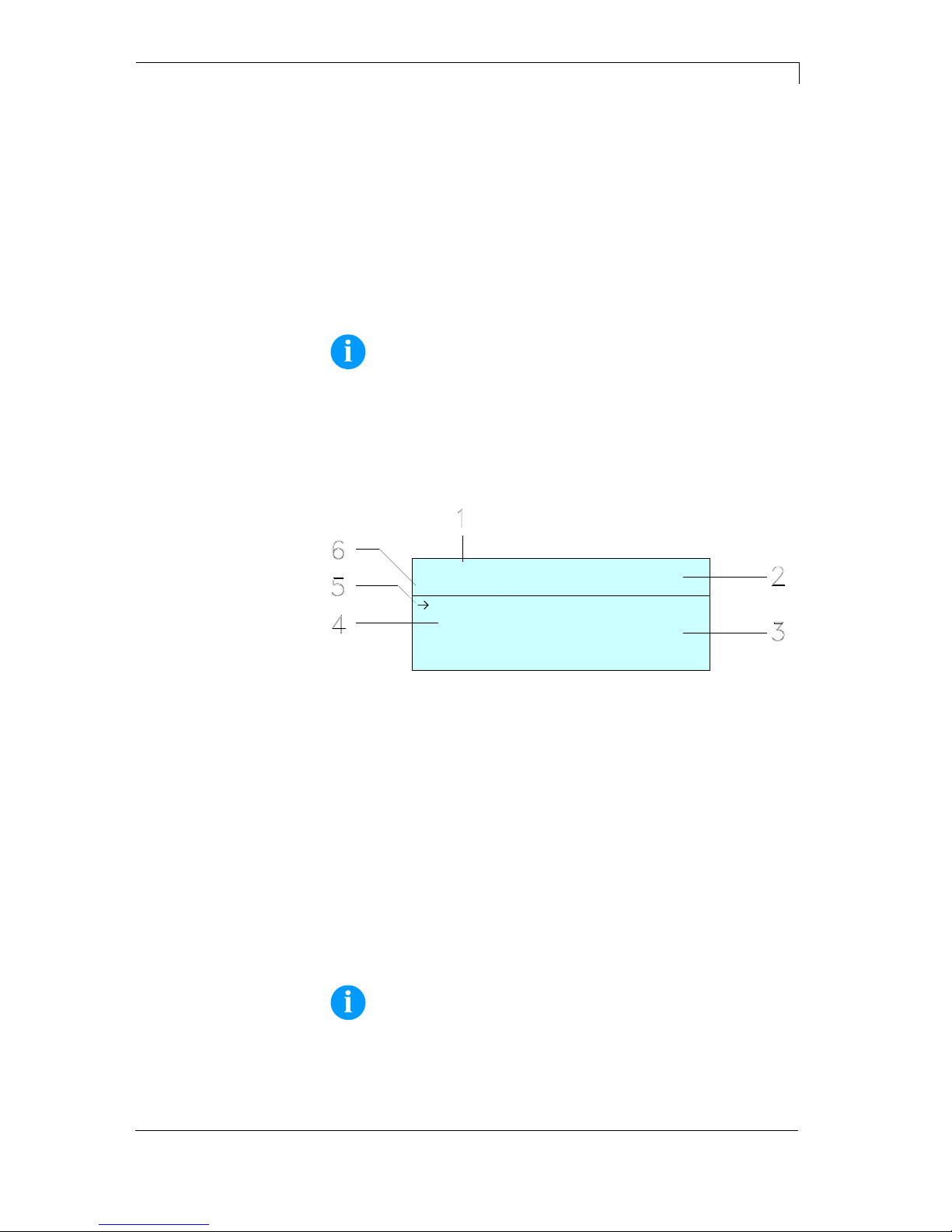
DuoPrint Series Compact Flash Card / USB Memory Stick
10.15 Operating Manual 59
8 Compact Flash Card / USB Memory Stick
8.1 General Information
On the back side of the label printer is the slot for the CF card and the
USB port for inserting the USB memory stick.
The mass storage menu (memory menu) permits the access to CF
cards or USB memory sticks attached to the printer. Among loading
and saving labels simple operations of contents are possible such as
delete files/directories, copy files/directories or formatting.
NOTICE!
In case of a malfunction of the original memory medium it is
recommend to copy the most important data by means of a
commercial Card Reader.
8.2 Display Structure
Load layout
A:\STANDARD
File_name1.prn
File_name2.prn
File_name3.prn
File_name4.prn
1 = Current function
2 = 2-lined header
3 = Scroll range
4 = File names / directory names
5 = Marking of the selected file (cursor)
6 = Current path (drive:\directory)
The two-line header (2) contains the current function name (1) and the
current path (6).
The four-line scroll range indicates a list of files/directories. The first
entry (marked with an arrow) is the active one. To this file/directory
and/or these files/directories refer all actions.
NOTICE!
Three drives are available.
A:\ indicates the CF card.
U:\ indicates the USB memory stick.
U:\ (only one stick can be inserted)
R:\ indicates the RAM (ZPL Emulation).
Page 60
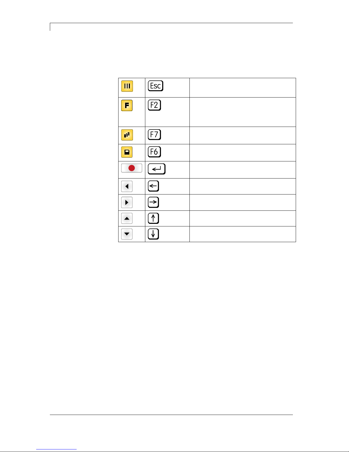
Compact Flash Card / USB Memory Stick DuoPrint Series
60 Operating Manual 10.15
8.3 Navigation
The memory menu is operated with the keys of the foil keyboard of
the control unit or with different function keys of an attached USB
keyboard.
Return to the previous menu.
Function Load layout: Change to the File
Explorer.
File Explorer: Change to the 'context
menu'.
Select a file/directory if a multiple
selection is possible.
Main menu: Access to the memory menu.
File Explorer: Create a new file.
Start the current function for the active
file/directory.
Change to the superordinate directory.
Change to the currently marked directory.
In the current directory scroll upwards.
In the current directory scroll downwards.
Page 61
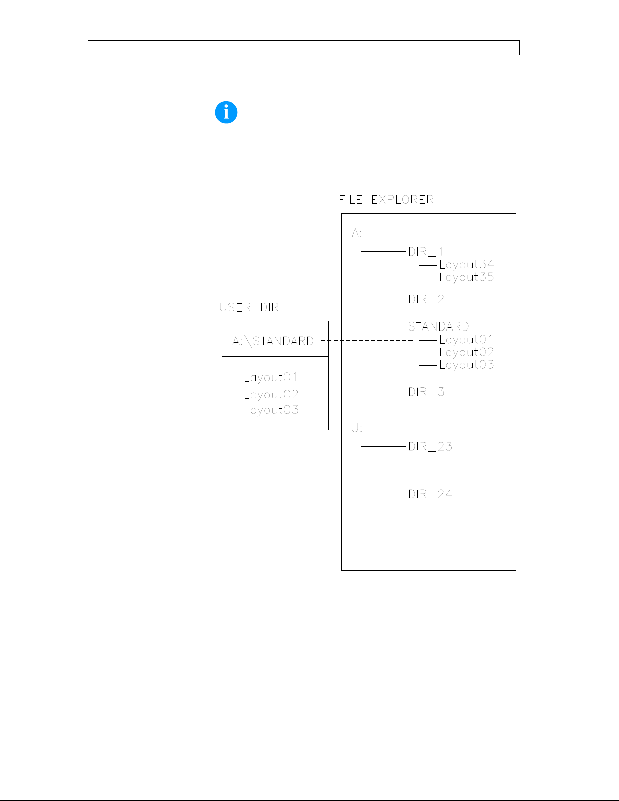
DuoPrint Series Compact Flash Card / USB Memory Stick
10.15 Operating Manual 61
8.4 Define User Directory
NOTICE!
An user directory is to be defined:
before using and/or navigating through the memory menu.
if formatting of CF card is effected at PC and thus the
STANDARD directory was not created automatically.
The user directory is the root directory in which the user saves usually
the most frequently used files/layouts. The utilisation of the user
directory permits the quick and direct access to the files saved in the
defined user directory. The definition of an user directory saves thus a
long search of the file to be printed.
Page 62
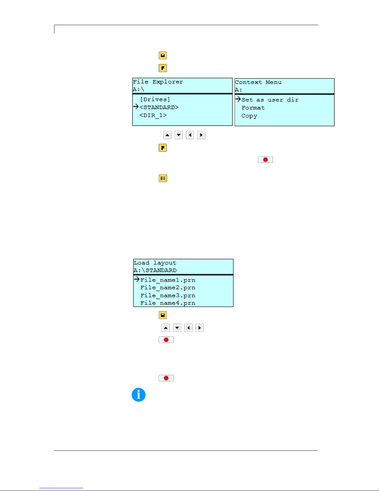
Compact Flash Card / USB Memory Stick DuoPrint Series
62 Operating Manual 10.15
Press key
to access to the memory menu.
Press key
to call the File Explorer.
Press keys , , , to select the directory.
Press key
to display all available functions.
Select the function Set as user dir and press key
to confirm the
selection.
Press key
as long as the printer returned to the main menu.
At the next start of the memory menu the selected directory is
displayed as user directory.
8.5 Load Layout
Loads a layout within a defined user directory. The function allows
quick access to the desired layout as only layout files are displayed
and directories hidden.
Press key
to access to the memory menu.
Press keys
, , , to select the layout to be printed.
Press key
to confirm the selection.
The printer display shows automatically the window to insert the
number of copies which are to print.
Select the number of copies which are to be printed.
Press key
to start the print order.
NOTICE!
The directory CANNOT be changed here. A change of directory
MUST be made in the File Explorer with the function Change
directory.
Page 63
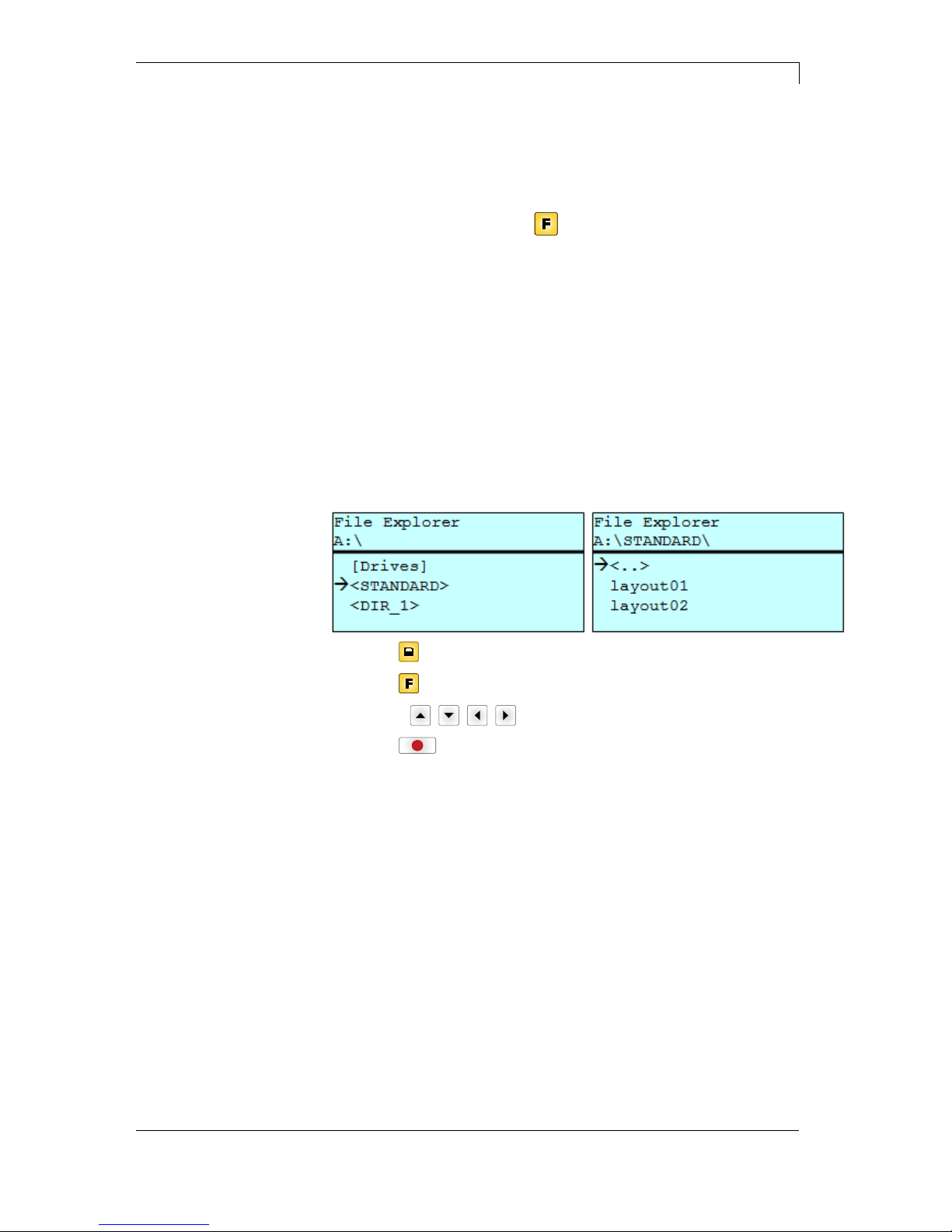
DuoPrint Series Compact Flash Card / USB Memory Stick
10.15 Operating Manual 63
8.6 File Explorer
The File Explorer is the file manager of the printing system. The File
Explorer provides the main functions for the user interface of memory
menu.
In the user directory, press key
to access to the File Explorer.
Following functions are available:
Change drive and/or directory
Load file
Save layout and/or configuration
Delete file(s)
Format CF card
Copy file(s)
Selection of drive and/or directory in which the files are saved.
Press key to access to the memory menu.
Press key
to call the File Explorer.
Press keys
, , , to select the directory.
Press key
to confirm the selection.
The selected directory is now displayed.
Change drive/directory
Page 64
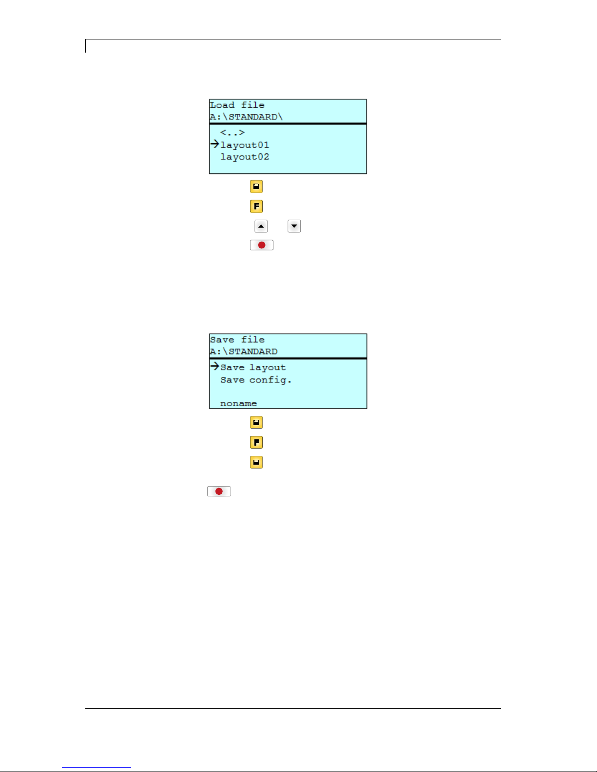
Compact Flash Card / USB Memory Stick DuoPrint Series
64 Operating Manual 10.15
Loads a file. This can be a configuration saved before, a layout, etc.
Press key
to access to the memory menu.
Press key
to call the File Explorer.
Press keys
and to select the file.
Press key
to load the selected file.
If the selected file is a layout, then the number of copies to print can
be entered immediately.
Saves the currently loaded layout under the selected name.
Press key
to access to the memory menu.
Press key
to call the File Explorer.
Press key
to change to the menu Save file.
Selct the function Savel layout and confirm the selection with key
.
If an USB keyboard is attached a new file name for noname can be
assigned.
Load file
Save layout
Page 65
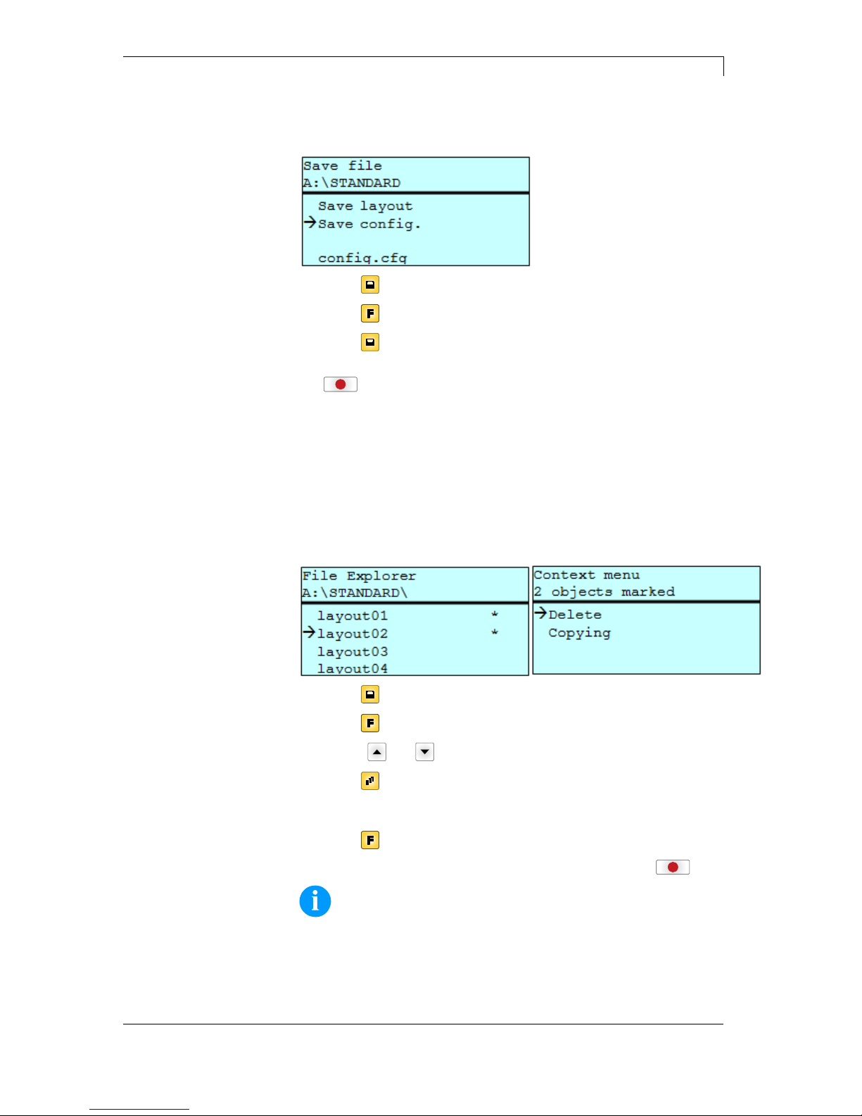
DuoPrint Series Compact Flash Card / USB Memory Stick
10.15 Operating Manual 65
Saves the complete, current printer configuration under the selected
name.
Press key
to access to the memory menu.
Press key
to call the File Explorer.
Press key
to change to the menu Save file.
Selct the function Save configuration and confirm the selection with
key
.
If an USB keyboard is attached a new file name for config.cfg can be
assigned.
Deletes one or more files and/or directories irrevocably. With the
deletion of a directory both the contained files and the subdirectories
are deleted.
Press key to access to the memory menu.
Press key
to call the File Explorer.
Press keys
and to select the file.
Press key
to mark the files which are to be deleted. The marked
entries are listed with *. Repeat this procedure until all desired files
and/or directories are marked for deletion.
Press key
to call the context menu.
Select the function Delete and confirm the selection with key
.
NOTICE!
The deleting procedure is irreversible!
Save configuration
Delete file(s)
Page 66
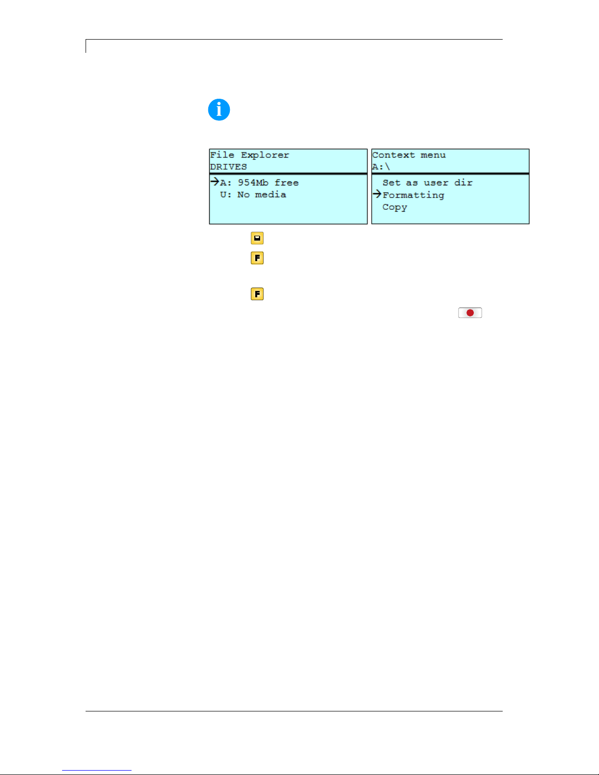
Compact Flash Card / USB Memory Stick DuoPrint Series
66 Operating Manual 10.15
Formats irrevocably the memory card.
NOTICE!
USB sticks cannot be formatted at the printer!
Press key to access to the memory menu.
Press key
to call the File Explorer.
Select the drive which is to format with the navigation keys.
Press key
to call the context menu.
Select the function Format and confirm the selection with key
.
Formatting
Page 67
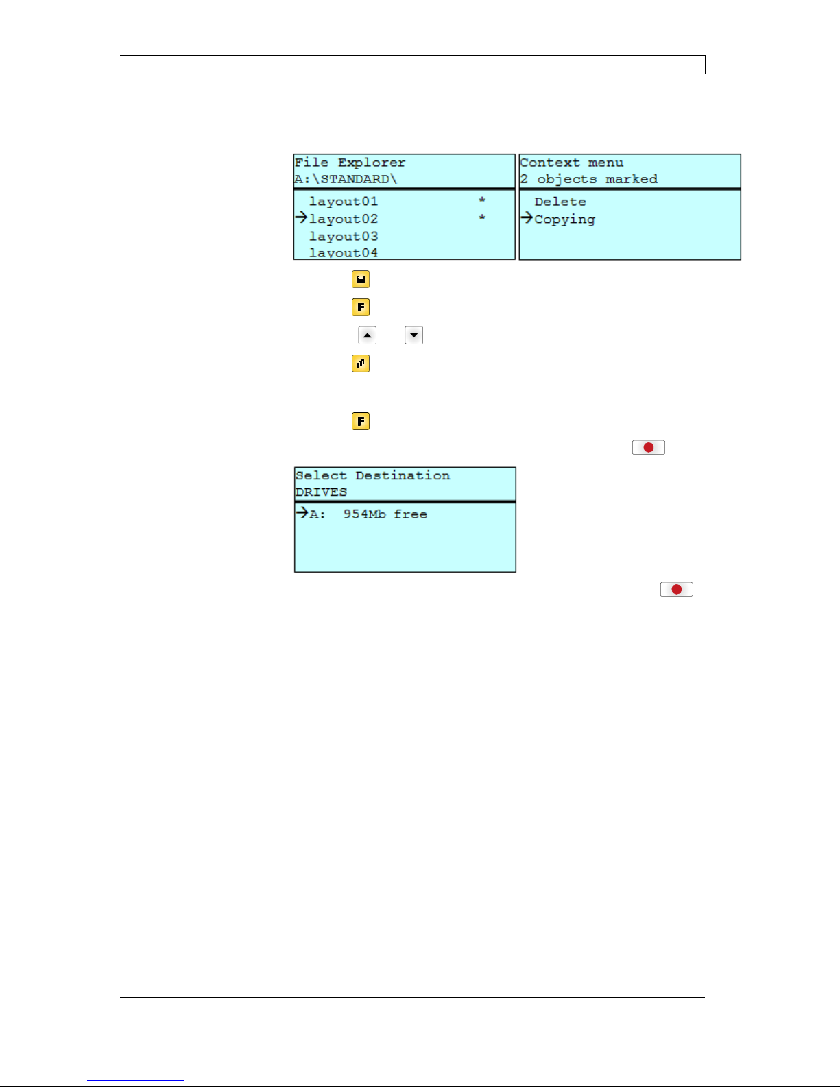
DuoPrint Series Compact Flash Card / USB Memory Stick
10.15 Operating Manual 67
Creates a duplicate of the original file and/or the original directory to
make changes independently of the original.
Press key to access to the memory menu.
Press key
to call the File Explorer.
Press keys
and to select the file.
Press key
to mark the files which are to be copied. The marked
entries are listed with *. Repeat this procedure until all desired files
and/or directories are marked for copying.
Press key
to call the context menu.
Select the function Copy and confirm the selection with key
.
Select the target storage with the navigation keys and press key
to confirm the selection.
Copying
Page 68
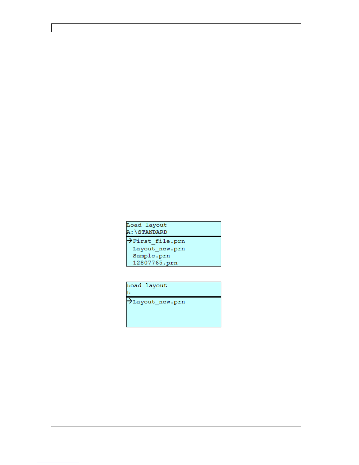
Compact Flash Card / USB Memory Stick DuoPrint Series
68 Operating Manual 10.15
8.7 Firmware Update
Starting from firmware version 1.58 it is possible to make a firmware
update also via the memory menu. Both the USB stick as well as the
CF card can be used for this.
On the CF card / USB memory stick a directory is created in which the
necessary update files are stored (firmware.prn, data.prn). By means
of the function Load file the file firmware.prn is selected/loaded. In the
first step the printer executes the firmware update. After the necessary
restart automatically the file data.prn is loaded. In this way the
remaining components were updated. is After a renewed restart the
update procedure is finished.
8.8 Filter
For certain functions a filter mask or a file name of a file which is to be
saved can be entered. This input is indicated in the path line. It is
possible with the filter mask to look for certain files. For example, with
the input of 'L' only the files are listed whose character string starts
with 'L' (regardless of upper and lower cases).
Procedure
Without filter
With filter
Page 69
DuoPrint Series Maintenance and Cleaning
10.15 Operating Manual 69
9 Maintenance and Cleaning
DANGER!
Risk of death by electric shock!
Disconnect the label printer from power supply
before performing any maintenance work.
NOTICE!
When cleaning the label printer, personal protective equipment
such as safety goggles and gloves are recommended.
Maintenance task Frequency
General cleaning (see section
9.1, page 70).
As necessary.
Cleaning printer roller (see
section 9.2, page 70).
Each time the label roll is
changed or when the printout and
label transport are adversely
affected.
Cleaning printhead (see section
9.3, page 71).
Each time the transfer ribbon is
changed or when the printout is
adversely affected.
Cleaning label photocell (see
section 9.4, page 72).
When exchanging the label roll.
Replacing printhead (see
section 9.5, page 73).
In case of errors in printout.
NOTICE!
The handling instructions for the use of Isopropanol (IPA) must
be observed. In the case of skin or eye contact, immediately
wash off the fluid thoroughly with running water. If the irritation
persists, consult a doctor. Ensure good ventilation.
WARNING!
Risk of fire by easily inflammable label soluble!
When using label soluble, dust must be completely
removed from the label printer and cleaned.
Maintenance
schedule
Page 70
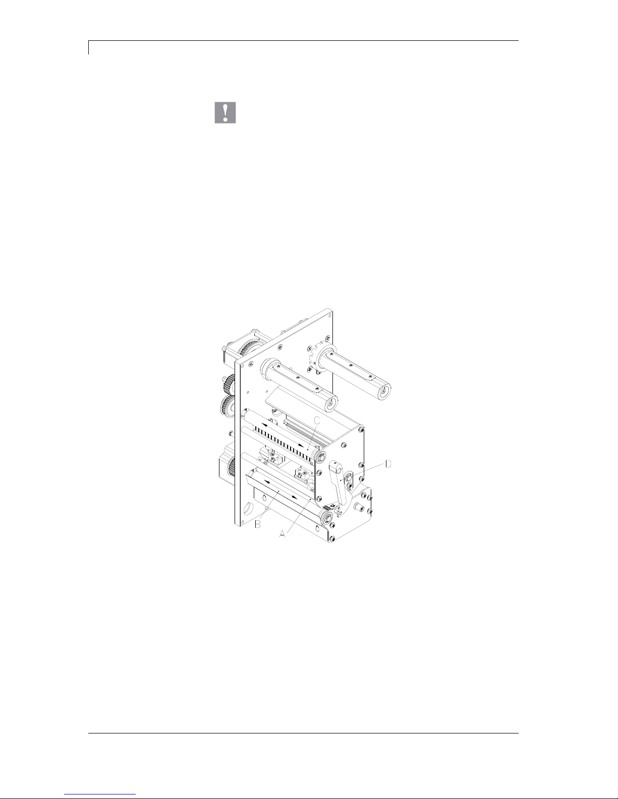
Maintenance and Cleaning DuoPrint Series
70 Operating Manual 10.15
9.1 General Cleaning
CAUTION!
Abrasive cleaning agents can damage the label printer!
Do not use abrasives or solvents to clean the outer
surface of the label printer.
Remove dust and paper fuzz in the printing area with a soft
brush or vacuum cleaner.
Clean outer surfaces with an all-purpose cleaner.
9.2 Cleaning the Printer Roller
A soiled print roll can lead to reduced print quality and can affect
transport of material.
Figure 11
1. Open printer cover.
2. Turn red lever (D) counter clockwise to lift up the printhead (A).
3. Remove labels and transfer ribbon form the label printer.
4. Remove deposits with roller cleaner and a soft cloth.
5. Turn the roller (B + C) manually step by step to clean the
complete roller (only possible when printer is switched off, as
otherwise the step motor is full of power and the roller is kept in its
position).
Page 71
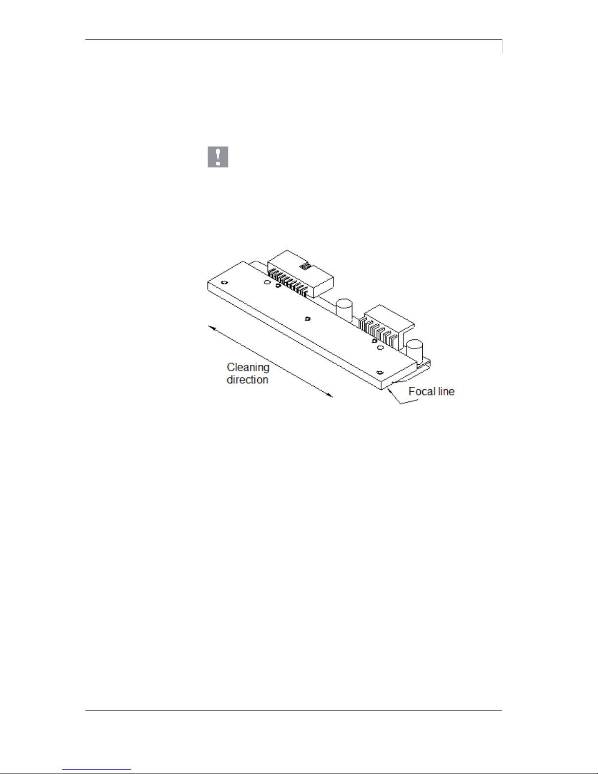
DuoPrint Series Maintenance and Cleaning
10.15 Operating Manual 71
9.3 Cleaning the Printhead
Printing can cause accumulation of dirt at printhead e.g. by colour
particles of transfer ribbon, and therefore it is necessary to clean the
printhead in regular periods depending on operating hours,
environmental effects such as dust etc.
CAUTION!
Printhead can be damaged!
Do not use sharp or hard objects to clean the
printhead.
Do not touch protective glass layer of the printhead.
Figure 12
1. Open printer cover.
2. Turn red lever (D, in Figure 11) anticlockwise to lift up the
printhead.
3. Remove labels and transfer ribbon from the label printer.
4. Clean printhead surface with special cleaning pen or a cotton
swab dipped in pure alcohol.
5. Allow printhead to dry for 2-3 minutes before commissioning the
printer.
Page 72
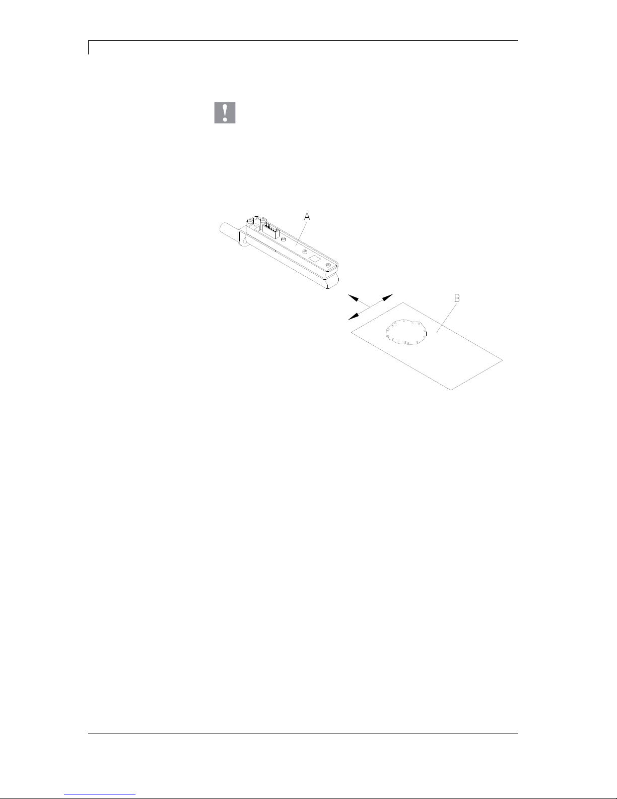
Maintenance and Cleaning DuoPrint Series
72 Operating Manual 10.15
9.4 Cleaning the Label Photocell
CAUTION!
Label photocell can be damaged!
Do not use sharp or hard objects or solvents to clean
the label photocell.
The label photocell can become dirtied with paper dust and this can
adversely affect label detection.
Figure 13
1. Open printer cover.
2. Turn red lever anticlockwise to lift up the printhead.
3. Remove labels and transfer ribbon from the label printer.
4. Blow out the photocell (A) with pressure gas spray.
Observe strictly the instructions on the spray can!
5. Clean the label photocell (A) additionally with a cleaning card (B)
before soaked in pure alcohol. Move the cleaning card from one
side to the other (see illustration).
6. Reload the labels and transfer ribbon (see chapter 6 Loading
Media, page 33).
Page 73
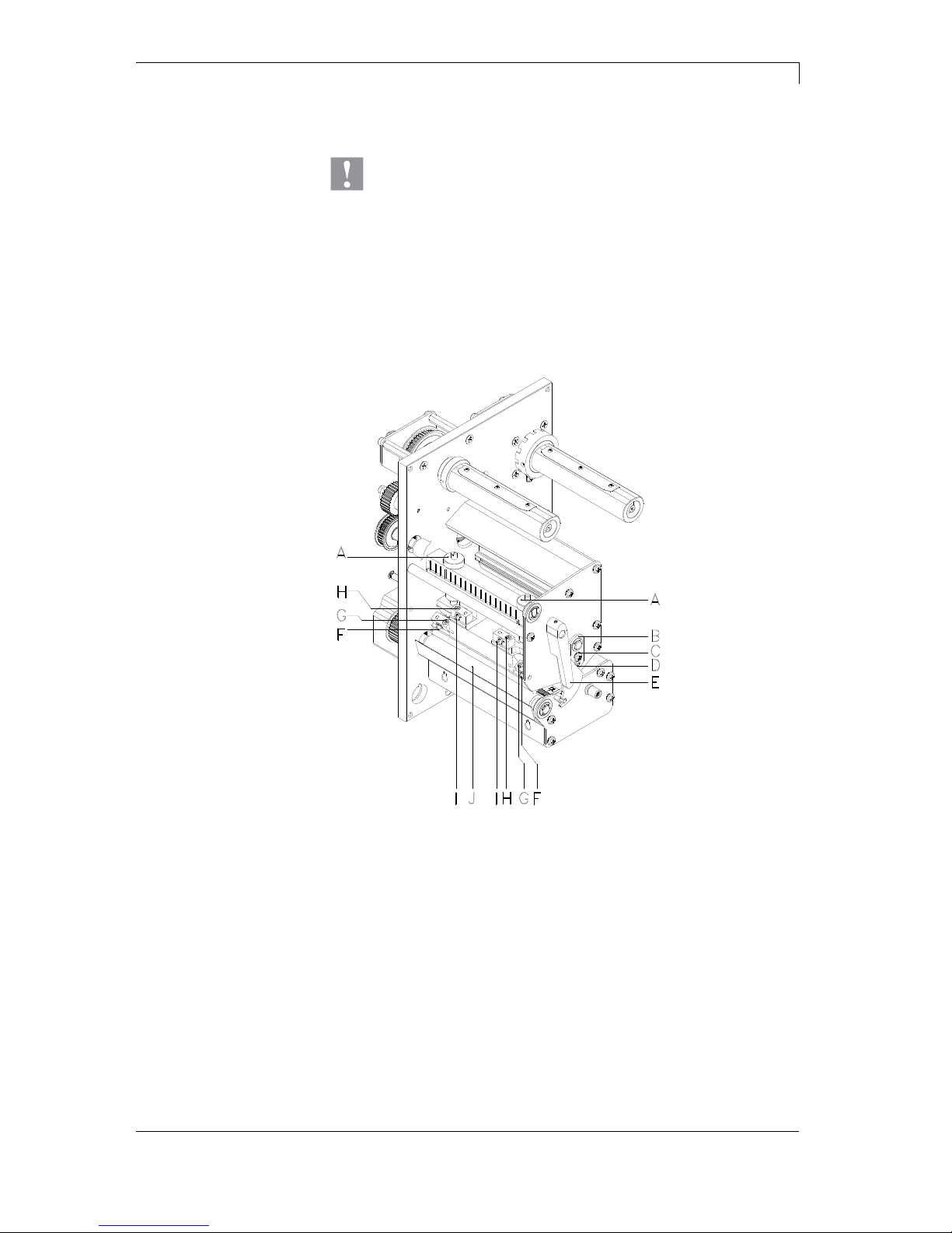
DuoPrint Series Maintenance and Cleaning
10.15 Operating Manual 73
9.5 Replacing the Printhead
CAUTION!
The printhead can be damaged by static electricity discharges
and impacts!
Set up the device on a grounded, conductive surface.
Ground your body, e.g. by wearing a grounded wristband.
Do not touch contacts on the plug connections.
Do not touch the printhead with hard objects or your
hands.
Figure 14
1. Open the printer cover.
2. Remove labels and transfer ribbon from the label printer.
3. When printhead is closed, loosen the fixing screws (G).
4. Remove the label guiding between the printheads.
5. Turn red lever (E) anticlockwise to lift up the printhead.
6. If the printhead (5) is not disengaged on the pressure roller (J),
continue loosen the fixing screws (G).
7. Remove the printhead carefully to the front until you can reach the
plug connections.
8. Remove plug connections and then remove printhead.
Removing the
printhead
Page 74
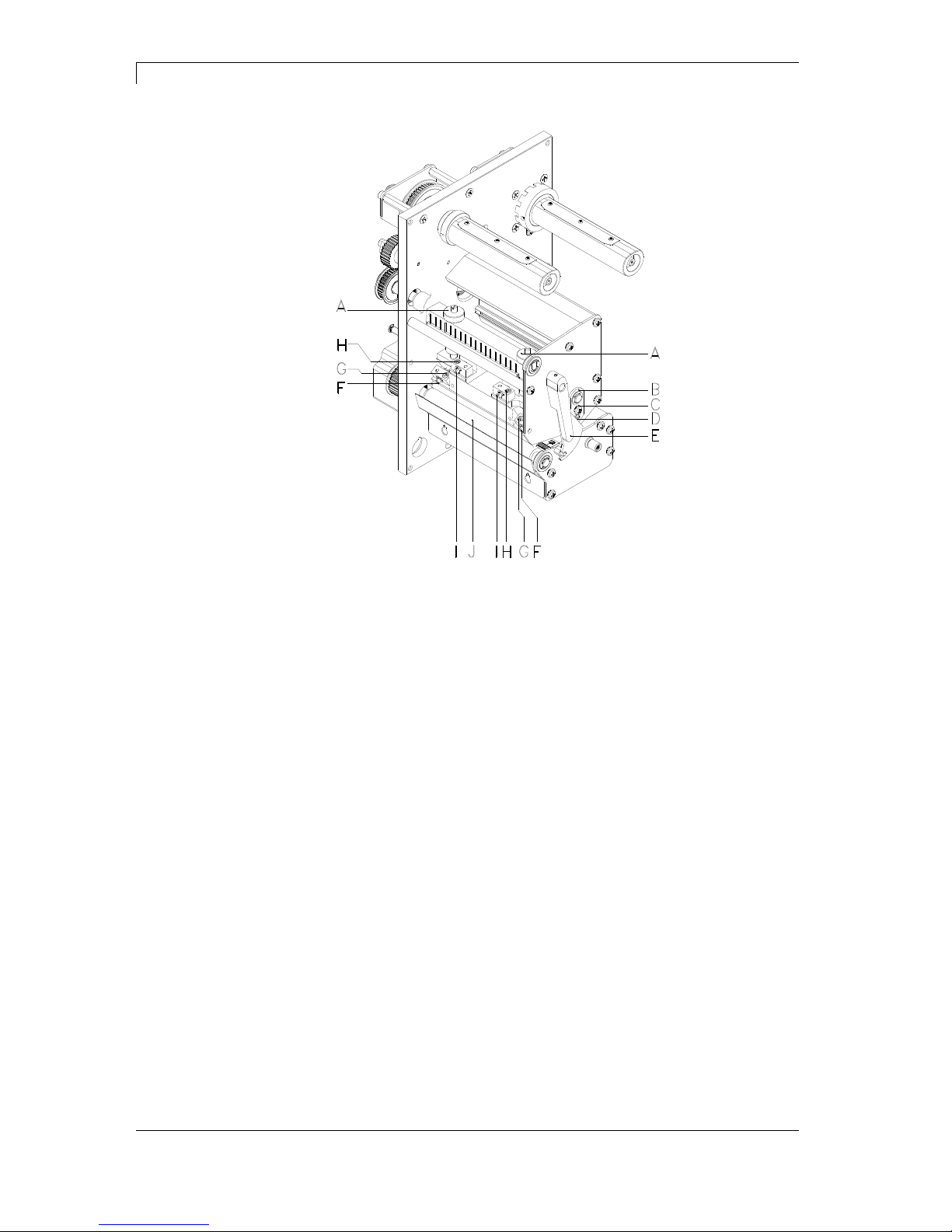
Maintenance and Cleaning DuoPrint Series
74 Operating Manual 10.15
Figure 15
1. Attach plug connections.
2. Position printhead in printhead mounting bracket in such a way
that the pins are secured in the corresponding holes in the head
plate.
3. Lightly keep printhead mounting bracket on the printer roller with
one finger and check for correct positioning of the printhead.
4. Screw in fixing screws (G) and tighten it.
5. Install again the label guiding.
6. Reload labels and transfer ribbon (see chapter 6 Loading Media,
page 33).
7. Check resistance value on the type plate of printhead and if
necessary change the value in the menu Service functions/Heater
resistance.
Installing the printhead
Page 75

DuoPrint Series Maintenance and Cleaning
10.15 Operating Manual 75
9.6 Adjusting the Printhead
An important characteristic for a high quality print is the parallelism of
the focal line of the thermal printhead to the pressure roll. Because of
the fact that the position of focal line of the printhead depends on
fluctuations caused by production, it is necessary to adjust the
parallelism.
The form of the CornerType printhead needs the setting of parallelism
in direction of the adjusting angle and in horizontal position. It needs a
little bit of experience to know in which direction you have to adjust the
printhead to receive a high quality printing.
1. Loosen the screws (G oder H, Figure 15) with a hexagon key by
approx. ¼ rotations.
2. Adjust the parallelism with the adjusting screws (E or I, Figure 15).
Clockwise = printhead moves backwards
Counter clockwise = printhead moves forwards
3. Adjust the parallelism as long as the printing result comes up to
your full expectation.
4. Tighten again screws (G or H, Figure 15).
5. Start a print order with approx. 10 labels and control the correct
passage of transfer ribbon.
After adjusting parallelism and no even strong pressure exists over
the complete print width, by means of a plate (6) you can set the
balance as follows:
1. Loosen screw (C, Figure 15) with a screwdriver by approx. ¼
rotations.
2. In order to achieve a pressure balance, turn the excentric bolt (D,
Figure 15) as long as the printing result comes up to your full
expectation.
3. Tighten again screw (C, Figure 15).
4. Start a print order with approx. 10 labels and control the correct
passage of transfer ribbon.
Parallelism
Pressure balance
right/left
Page 76

Maintenance and Cleaning DuoPrint Series
76 Operating Manual 10.15
Increasing the printhead contact pressure leads to an improvement of
the print image density on the corresponding side and to a shifting of
the ribbon feed path in the corresponding direction.
CAUTION!
Damage of printhead by unequal use!
Change factory settings only in exceptional cases.
The selection of the smallest value can optimise the life cycle of
printhead.
1. Turn pressure screws (A, Figure 15) to change the pressure of
printhead.
2. Turning the pressure screws (A, Figure 15) as far as they will go
in clockwise direction results in a pressure increase of 10N in
contrast to the factory setting.
3. Turning the pressure screws (A, Figure 15) exactly one rotation
from the right stop position counter clockwise results in the factory
settings.
NOTICE!
It is importantly that the knurled button which is coated with
protective lacquer is not removed from the pressure screw as
otherwise the above mentioned settings are faulty.
Pressure
Page 77
DuoPrint Series Error correction
10.15 Operating Manual 77
10 Error correction
Error message Cause Remedy
1 Line too high
Line rises up completely or
partly over the upper edge of
label.
Move line down (increase Y
value).
Check rotation and font.
2 Line too low
Line rises up completely or
partly over the bottom edge of
label.
Move line up (reduce X value).
Check rotation and font.
3 Character set
One res. several characters of
the text is res. are not available
in the selected font.
Change text.
Change font.
4 Unknown code type
Selected code is not available. Check code type.
5 Unvalid position
Selected position is not
available.
Check position.
6 CV font
Selected font is not available. Check font.
7 Vector font
Selected font is not available. Check font.
8 Measuring label
While measuring no label was
found.
Set label length is too large.
Check label length and if labels
are inserted correctly.
Restart measuring anew.
9 No label found
No label available.
Soiled label photocell.
Labels not inserted correctly.
Insert new label roll.
Check if labels are inserted
correctly.
Clean the label photocell.
10 No ribbon
During the print order the
ribbon roll becomes empty
(front printhead).
Defect at the transfer ribbon
photocell (front photocell).
Change transfer ribbon.
Check transfer ribbon photocell
(service functions).
11 COM FRAMING
Stop bit error. Check stop bits.
Check baud rate.
Check cable (printer and PC).
12 COM PARITY
Parity error. Check parity.
Check baud rate.
Check cable (printer and PC).
13 COM OVERRUN
Loss of data at serial interface
(RS-232).
Check baud rate.
Check cable (printer and PC).
Page 78
Error correction DuoPrint Series
78 Operating Manual 10.15
Error message Cause Remedy
14 Field numer
Received line number is invalid
at RS-232 and Centronics.
Check sent data.
Check connection PC - printer.
15 Length mask
Invalid length of received mask
statement.
Check sent data.
Check connection PC - printer.
16 Unknown mask
Transferred mask statement is
invalid.
Check sent data.
Check connection PC - printer.
17 Missing ETB
No end of data found. Check sent data.
Check connection PC - printer.
18 Invalid character
One res. several characters of
the text is res. are not available
in the selected font.
Change text.
Change font.
19 Invalid statement
Unknown transferred data
record.
Check sent data.
Check connection PC - printer.
20 Invalid check digit
For check digit control the
entered res. received check
digit is wrong.
Calculate check digit anew.
Check code data.
21 Invalid SC number
Selected SC factor is invalid for
EAN res. UPC.
Check SC factor.
22 Invalid number of
digits
Entered digits for EAN res.
UPC are invalid
< 12; > 13.
Check number of digits.
23 Check digit
calculation
Selected check digit calculation
is not available in the bar code.
Check calculation of check
digit.
Check bar code type.
24 Invalid extension
Selected zoom factor is not
available.
Check zoom factor.
25 Offset sign
Entered sign is not available. Check offset value.
26 Offset value
Entered offset value is invalid. Check offset value.
27 Printhead
temperature
Printhead temperature is too
high.
Defective printhead sensing
device.
Reduce contrast.
Change printhead.
28 Cutter error
With cut an error occurred.
Paper jam.
Check label run.
Check cutter run.
29 Invalid parameter
Entered data do not correspond
to the characters allowed from
the application identifier.
Check code data.
Page 79
DuoPrint Series Error correction
10.15 Operating Manual 79
Error message Cause Remedy
30 Application
Identifier
Selected application identifier is
not available in GS1-128.
Check code data.
31 HIBC definition
F Missing HIBC system sign.
Missing primary code.
Check definition of HIBC code.
32 System clock
Real Time Clock function is
selected but the battery is
empty.
Defective RTC.
Change battery.
Change RTC component.
33 No CF interface
Interrupted connection CPU CF card.
Defective CF card interface.
Check connection CPU - CF
card interface.
Check CF card interface.
34 No print memory
No print CF found. Check CF assembly on CPU.
35 Cover open
At start of a print order the
printhead is open.
Close the printhead and start
print order anew.
36 BCD invalid format
BCD error
Invalid format for the
calculation of Euro variable.
Check entered format.
37 BCD overflow
BCD error
Invalid format for the
calculation of Euro variable.
Check entered format.
38 BCD division
BCD error
Invalid format for the
calculation of Euro variable.
Check entered format.
39 FLASH ERROR
Flash component error. Run a software update.
Change CPU.
40 Length command
Invalid length of the received
command statement.
Check data sent.
Check connection PC - printer.
41 No drive
CF card not found / not
correctly inserted.
Insert CF card correctly.
42 Drive error
Impossible to read CF card
(faulty).
Check CF card, if necessary
change it.
43 Not formatted
CF Card not formatted. Format CF card.
44 Delete current
directory
Attempt to delete the actual
directory.
Change directory.
45 Path too long
Too long indication of path. Indicate a shorter path.
Page 80
Error correction DuoPrint Series
80 Operating Manual 10.15
Error message Cause Remedy
46 Drive write-
protected
Memory card is write-protected. Deactivate write protection.
47 Directory not file
Attempt to indicate a directory
as file name.
Correct your entry.
48 File already open
Attempt to change a file during
an access is active.
Select another file.
49 No file/directory
File does not exist on CF card. Check file name.
50 Invalid file name
File name contains invalid
characters.
Correct entry of name, remove
special characters.
51 Internal file error
Internal file system error. Please contact your distributor.
52 Root full
The max. number (64) of main
directory entries is reached.
Delete at least one main
directory entry and create
subdirectories.
53 Drive full
Maximum CF capacity is
reached.
Use new CF Card, delete no
longer required files.
54 File/directory
exists
The selected file/directory
already exists.
Check name, select a different
name.
55 File too large
During copying procedure not
enough memory space onto
target drive available.
Use a larger target card.
56 No update file
Errors in update file of
firmware.
Start update file anew.
57 Invalid graphic file
The selected file does not
contain graphic data.
Check file name.
58 Directory not empty
Attempt to delete a not empty
directory.
Delete all files and subdirectories in the desired
directory.
59 No interface
No CF card drive found. Check connection of CF card
drive.
Contact your distributor
60 No CF card
No CF card is inserted. Insert CF card in the slot.
61 Webserver error
Error at start of web server. Please contact your distributor.
62 Wrong FPGA
The direct print module is
equipped with the wrong
FPGA.
Please contact your distributor.
63 End position
The label length is too long.
The number of labels per cycle
is too much.
Check label length res. the
number of labels per cycle.
Page 81
DuoPrint Series Error correction
10.15 Operating Manual 81
Error message Cause Remedy
64 Zero point
Defective photocell. Change photocell.
65 Compressed air
Pressure air is not connected. Check pressure air.
66 External releaser
External print release signal is
missing.
Check input signal.
67 Row too long
Wrong definition of column
width res. number of columns.
Reduce the column width res.
correct the number of columns.
68 Scanner
The connected bar code
scanner signals a device error.
Check the connection
scanner/printer.
Check scanner (dirty).
69 Scanner NoRead
Bad print quality.
Printhead completely soiled or
defective.
Print speed too high.
Increase contrast.
Clean printhead or exchange (if
necessary).
Reduce print speed.
70 Scanner data
Scanned data does not
correspond to the data which is
to print.
Exchange printhead.
71 Invalid page
As page number either 0 or a
number > 9 is selected.
Select a number between 1
and 9.
72 Page selection
A page which is not available is
selected.
Check the defined pages.
73 Page not defined
The page is not defined. Check the print definition.
74 Format user guiding
Wrong format for customised
entry.
Check the format string.
75 Format date/time
Wrong format for date/time. Check the format string.
76 Hotstart CF
No CF card found. If option hotstart was activated,
a CF card must be inserted.
Switch off the printer before
inserting the memory card.
77 Flip/Rotate
Selection of print of several
columns and also mirror/rotate.
It is only possible to select one
of both functions.
78 System file
Loading of temporary hotstart
files.
Not possible.
79 Shift variable
Faulty definition of shift times
(overlapping times).
Check definition of shift times.
80 GS1 Databar
General GS1 Databar error. Check definition and parameter
of GS1 Databar code.
81 IGP error
Protocol error IGP. Check sent data.
Page 82
Error correction DuoPrint Series
82 Operating Manual 10.15
Error message Cause Remedy
82 Time generation
Printing creation was still active
at print start.
Reduce print speed.
Use printers' output signal for
synchronisation.
Use bitmap fonts to reduce
generating time.
83 Transport protection
Both DPM position sensors
(start/end) are active.
Displace zero point sensor
Check sensors in service
functions menu
84 No font data
Font and web data is missing. Run a software update.
85 No layout ID
Label ID definition is missing. Define label ID onto the label.
86 Layout ID
Scanned data does not
correspond to defined ID.
Wrong label loaded from CF
card.
87 RFID no label
RFID unit cannot recognise a
label.
Displace RFID unit or use an
offset.
88 RFID verify
Error while checking
programmed data.
Faulty RFID label.
Check RFID definitions
89 RFID timeout
Error at programming the RFID
label.
Label positioning.
Faulty label.
90 RFID data
Faulty or incomplete definition
of RFID data.
Check RFID data definitions.
91 RFID tag type
Definition of label data does not
correspond with the used label.
Check storage partitioning of
used label type
92 RFID lock
Error at programming the RFID
label (locked fields).
Check RFID data definitions.
Label was already
programmed.
93 RFID programming
Error at programming the RFID
label.
Check RFID definitions.
94 Scanner timeout
The scanner could not read the
bar code within the set timeout
time.
Defective printhead.
Wrinkles in transfer ribbon.
Scanner wrong positioned.
Timeout time too short.
Check printhead.
Check transfer ribbon.
Position scanner correctly,
corresponding to the set
feeding.
Select longer timeout time.
Page 83
DuoPrint Series Error correction
10.15 Operating Manual 83
Error message Cause Remedy
95 Scanner layout
difference
Scanner data does not
correspond to bar code data.
Check adjustment of scanner.
Check scanner settings /
connection.
96 COM break
Serial interface error. Check settings for serial data
transmission as well as cable
(printer-PC).
97 COM general
Serial interface error. Check settings for serial data
transmission as well as cable
(printer-PC).
98 No software
printhead FPGA
No printhead-FPGA data
available.
Please contact your
responsible distributor.
99 Load software
printhead FPGA
Error when programming
printhead-FPGA.
Please contact your
responsible distributor.
100 Upper position
Sensor signal up is missing
(option APL 100).
Check input signals /
compressed-air supply.
101 Lower position
Sensor signal down is missing
(option APL 100).
Check input signals /
compressed-air supply.
102 Vacuum plate empty
Sensor does not recognise a
label at vacuum plate
(option APL 100).
Check input signals /
compressed-air supply.
103 Start signal
Print order is active but device
not ready to process it.
Check start signal.
104 No print data
Print data outside the defined
label.
Selection of wrong module type
(design software).
Check selected module type.
Check selection of left/right
version.
105 Printhead
No original printhead is used. Check the used printhead.
Contact your distributor.
106 Invalid Tag type
Wrong Tag type.
Tad data do not match the Tag
type in the printer.
Adapt data or use the correct
Tag type.
107 RFID invalid
RFID module is not activated.
No RFID data can be
processed.
Activate RFID module or
remove RFID data from label
data.
108 GS1-128 invalid
Transferred GS1-128 bar code
is invalid.
Verify bar code data (see GS1128 bar code specification).
109 EPC parameter
Error at EPC calculation. Verify data (see EPC
specification).
Page 84
Error correction DuoPrint Series
84 Operating Manual 10.15
Error message Cause Remedy
110 Housing open
When starting the print order
the housing cover is not closed.
Close the housing cover and
start the print order anew.
111 EAN.UCC code
Transferred EAN.UCC code is
invalid.
Verify bar code data (see
corresponding specification).
112 Print carriage
Printing carriage does not
move.
Check gear belt (possibly
broken).
113 Applicator error
Error while using applicator. Check applicator.
114 Left position
Left final position switch is not
in correct position.
Check LEFT final position
switch for correct function and
position.
Check function of pneumatics
for cross traverse.
115 Right position
Right final position switch is not
in correct position.
Check RIGHT final position
switch for correct function and
position.
Check function of pneumatics
for cross traverse.
116 Print position
The print position is not correct. Check TOP and RIGHT final
position switch for correct
function and position.
Check pneumatics for function
117 XML parameter
The parameters in the XML file
are not correct.
Please contact your
responsible distributor.
118 Invalid variable
Transferred variable is invalid
with customized entry.
Select correct variable without
customized entry and transfer
it.
119 No ribbon
During the print order the
ribbon roll becomes empty
(rear printhead).
Defect at the transfer ribbon
photocell (rear photocell).
Change transfer ribbon.
Check transfer ribbon photocell
(service functions).
120 Wrong directory
Invalid target directory when
copying.
Target directory must not be
within the source directory.
Check target directory.
121 No label found
No label found at the rear
printhead (DuoPrint).
Soiled label photocell.
Labels not inserted correctly.
Insert new label roll.
Clean the label photocell.
Check if labels are inserted
correctly.
122 IP occupied
The IP address was already
assigned.
Assign a new IP address.
Page 85

DuoPrint Series Error correction
10.15 Operating Manual 85
Error message Cause Remedy
123 Print asynchronous
The label photocell do not work
in the order as it is expected
according to print data.
Check label size and gap size.
The settings of the photocell
are not correct.
Check label photocell settings.
Settings of label size and gap
size are not correct.
Check correct loading of label
material.
No label found at the rear
printhead.
Insert new label roll.
Soiled label photocell. Clean the label photocell.
Labels not inserted correctly. Check if labels are inserted
correctly.
124 Speed too slow
Print speed is too slow. Increase the speed of
customers' machine.
Page 86

Page 87
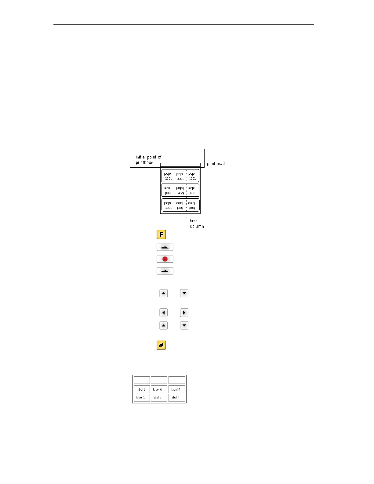
DuoPrint Series Additional Information
10.15 Operating Manual 87
11 Additional Information
11.1 Column Printing
With this label printer several columns can be printed, i.e. the
information of one column can be printed several times (depending on
its width) on a label. Caused by this the use of the complete print
width is possible and the generating time is enormously reduced.
For example 4 columns with a width of 25 mm or 2 columns with a
width of 50 mm can be printed onto a label with a width of 100 mm.
Please note that the first label is always the one with the largest x
coordinate, i.e. it has the largest distance to the printhead.
Press key
to access the function menu.
Press key
as long as you arrive the menu Label layout.
Press key
to confirm the selection.
Press key
as long as to the menu item Width/Columns.
Press keys
and to set the label width. The Width is the width of
one column, e.g. 20.0 mm.
Press keys
and to arrive the Column input field.
Press keys
and to change the number of columns, e.g. 4
columns with a label width of 20.0 mm.
Press key
to start the print with input of number of labels and
number of lines. The number of labels corresponds to the number of
labels that should be printed.
e.g. Columns: 3, Items: 4
The first four labels were printed but not labels 5 and 6.
Setting the print of
several columns
Page 88

Additional Information DuoPrint Series
88 Operating Manual 10.15
11.2 Password Protection
The supervisor programs a Compact Flash Card directly with the label
printer. He stores 10 different labels. As well he adjusts the print
parameters, like contrast, speed, etc. to the corresponding values.
The user is only supposed to read the labels from CF card and to print
them. Therefore the supervisor blocks the function menu and the entry
function by a password.
The label printer is connected to a PC. The user is only supposed to
take the labels dispensed by the label printer and stick them on. To
prevent, that the labels or the label printer set-up will not be changed,
the supervisor blocks all device functions (e.g. function menu, entry
menu, etc.) by a password.
The user has to change several texts before printing. It is not allowed
to change any masks (fonts, position, etc.). Therefore the supervisor
blocks the entry of mask and the function menu. By this means the
user indeed can print labels, but the set-up of label printer and the
masks of the label cannot be changed.
To receive a most flexible password protection, the device functions
will be divided into several function groups:
In the function menu the print parameters can be changed (contrast,
speed, mode, ...). The password protection prevents modifications at
the print settings.
With the functions of your Compact Flash Card lbels can be stored,
loaded, etc. The password protection has to decide if no access or
only readable access on CF card is allowed.
With key quant a print can be produced. In case the label printer is
connected to a PC, it can be useful, that the user is not able to
produce a print manually. So the password protection prevents that
prints can be produced manually.
Because of these different function groups the password protection is
very flexible. The label printer can be adjusted best to its actual order,
as only certain functions are blocked.
Example 1:
Example 2:
Example 3:
1. Function menu:
2. CF card:
3. Print functions:
Page 89
DuoPrint Series Additional Information
10.15 Operating Manual 89
In case no password is defined res. the password protection is not
activated, all functions can be used. In the function menu you will find
the menu item 'Password', where the password can be entered and
the password protection activated.
Press key
to change to the function menu.
Press key
as long as you arrived the menu Device settings.
Press key
to confirm the selection.
Press key
as long as you arrived the menu item Password.
Press key
to confirm the selection.
F Function menu
CF Compact Flash functions
D Print functions
If the password protection is active but the function menu not
protected, first of all the password (four-digit number, possible values
0000 - 9999) has to be entered. Now the modifications can be made.
The user can define the password in the first line (four-digit number).
Press key
to continue.
Press keys
and to activate/deactivate (Yes/No) the password
protection.
Press key
to change to the second line.
Press keys
and to block/open individual function groups.
Press keys
and to change to the next group.
F: Function menu 0...open
1...locked
CF: Compact Flash card 0...open
1...only reading access
2...access blocked
D: Device guiding 0...open
1...open
2...no manual print release
In order to execute a blocked function, first of all the valid password
has to be entered.
Press key
to confirm the entry. If the correct password is
entered then the desired function can be executed. If a wrong
password is entered, no error message appears but the device returns
to the main menu.
Definition of password
Activate blocked
function:
Page 90

Additional Information DuoPrint Series
90 Operating Manual 10.15
11.3 Photocells
NOTICE!
When using reflection photocells you should observe that the
label printer cover is closed and in this way other light (e.g.
working lamp) on the photocell is prevented.
For this photocell type the transmitter is at the top res. the receiver at
the bottom, i.e. the infra-red light is sent from the top. In this way the
label detection is also from the top. This photocell type is used for
standard adhesive labels with gap.
For this photocell type the transmitter and receiver are at the bottom,
i.e. the light is reflected by the label and taken over from the receiver.
This photocell type is used for white (light) continuous labels with a
black (dark) bar. The bar is the separator, i.e. it indicates the position
of gap and in this way the label start.
For this photocell type the transmitter is at the top res. the receiver at
the bottom, i.e. the infra-red light is sent from the top. The label
detection is, same as for the transmission photocell normal, from
the top. However, it is printed differently as for normal photocells, in
the translucent place; the label printer recognizes the opaque place as
gap. This photocell type is used frequently when printing foils.
For this photocell type the transmitter and receiver are at the bottom,
i.e. the light is reflected by the label and taken over from the receiver.
This photocell type is used for black (dark) continuous labels with a
white (light) bar. This bar is the separator, i.e. it indicates the position
of gap and in this way the start of label.
NOTICE!
When using transmission photocells inverse, the label printer
must measure a difference of 2.5 V and for reflection photocells
inverse 1 V between translucent and opaque material.
Otherwise the label printer does not recognize a difference
between label and gap (bar).
Transmission
photocell normal
Reflexion
photocell normal
Transmission
photocell inverse
Reflexion
photocell inverse
Page 91

DuoPrint Series Environmentally-Friendly Disposal
10.15 Operating Manual 91
12 Environmentally-Friendly Disposal
Manufacturers of B2B equipments are obliged to take-back and
dispose old equipment which was manufactured after 13 August 2005.
In principle, these old equipments may not be delivered to communal
collecting points. They may only be organised used and disposed by
the manufacturer. Valentin products accordingly labelled can therefore
in future be returned to Carl Valentin GmbH.
Thereupon old equipment is professionally disposed.
Thereby Carl Valentin GmbH observes all obligations in the context of
old equipment disposal in time and makes therewith the smooth
selling of products furthermore possible. Please understand that we
can only take-back equipment that is send free of carriage charges.
Further information is available from WEEE directive or our web site
www.carl-valentin.de.
Page 92

Page 93

DuoPrint Series Index
10.15 Operating Manual 93
13 Index
C
Column printing .................................................................................. 87
Compact Flash Card
Change directory ............................................................................ 63
Copying ........................................................................................... 67
Define user directory ................................................................. 61, 62
Delete file ........................................................................................ 65
Display structure ............................................................................. 59
Filter ................................................................................................ 68
Firmware update ............................................................................. 68
Formatting ....................................................................................... 66
Load file .......................................................................................... 64
Load layout ..................................................................................... 62
Navigation ....................................................................................... 60
Save configuration .......................................................................... 65
Save layout ..................................................................................... 64
Connecting printer .............................................................................. 30
Connector pin assignment (printer rear) ............................................ 30
Control inputs and outputs ................................................................. 23
E
Environmentally-friendly disposal ....................................................... 91
Error messages/Error corrections ...... 77, 78, 79, 80, 81, 82, 83, 84, 85
F
Function menu
Date/Time ....................................................................................... 54
Device settings ......................................................................... 44, 45
Dispenser I/O ...................................................................... 46, 47, 48
Interface .......................................................................................... 53
Label layout .............................................................................. 42, 43
Main menu ...................................................................................... 58
Material savings .................................................................. 50, 51, 52
Menu structure .................................................................... 38, 39, 40
Network ........................................................................................... 52
Print setting ..................................................................................... 41
Remote console .............................................................................. 52
Service functions .......................................................... 55, 56, 57, 58
I
Inputs/outputs ............................................................................... 22, 24
Installation .......................................................................................... 29
Instructions ........................................................................................... 5
Intended use ......................................................................................... 5
K
Keyboard ............................................................................................ 37
L
Loading media
Tear-off mode ................................................................................. 33
Transfer ribbon ............................................................................... 35
Page 94

Index DuoPrint Series
94 Operating Manual 10.15
M
Maintenance/cleaning
General cleaning ............................................................................. 70
Label photocell cleaning ................................................................. 72
Maintenance schedule .................................................................... 69
Print roller cleaning ......................................................................... 70
Printhead adjusting ......................................................................... 75
Printhead cleaning .......................................................................... 71
Printhead, replacing .................................................................. 73, 74
Material, loading ................................................................................. 33
O
Operating conditions ............................................................ 8, 9, 10, 11
P
Password protection ..................................................................... 88, 89
Photocells ........................................................................................... 90
Plug & Play ......................................................................................... 27
Printhead adjusting
Parallelism ...................................................................................... 75
Pressure ......................................................................................... 76
Pressure balance ............................................................................ 75
S
Safety Instructions ................................................................................ 7
Setting up printer ................................................................................ 29
Start-up ............................................................................................... 31
T
Two-colour printing
Colour processing ..................................................................... 16, 17
Correcting the printout .................................................................... 15
Error correction ............................................................................... 17
Label design ................................................................................... 13
Label photocells .............................................................................. 14
Label saving .............................................................................. 15, 16
Printhead 2 Offset ........................................................................... 14
Test print ......................................................................................... 15
U
USB Stick
Change directory ............................................................................ 63
Copying ........................................................................................... 67
Delete file ........................................................................................ 65
Display structure ............................................................................. 59
Filter ................................................................................................ 68
Firmware update ............................................................................. 68
Load file .......................................................................................... 64
Load layout ..................................................................................... 62
Navigation ....................................................................................... 60
Save configuration .......................................................................... 65
Save layout ..................................................................................... 64
Page 95

Page 96

Carl Valentin GmbH
Neckarstraße 78 – 86 u. 94 . D-78056 Villingen-Schwenningen
Phone +49 (0)7720 9712-0 . Fax +49 (0)7720 9712-9901
[email protected] . www.carl-valentin.de
 Loading...