

Page 1

DHP-UM-020
Val Controls A/S • Limfjordsvej 3 • DK-6715 Esbjerg N • Tel. +45 7547 0600 • Fax +45 7547 0611
[email protected] • www.valcontrols.com
Revision: 12
1/38
USER MANUAL
Intelligent Hydraulic Positioner
IHP24-A
IHP24-AF
IHP24-B
IHP24-BF
IHP24-F
IHP24-I
Page 2

DHP-UM-020
Val Controls A/S • Limfjordsvej 3 • DK-6715 Esbjerg N • Tel. +45 7547 0600 • Fax +45 7547 0611
[email protected] • www.valcontrols.com
Revision: 12
2/38
Table of contents
1 General ......................................................................................................................................... 3
1.1 Safety instructions ................................................................................................................................ 3
2 Application .................................................................................................................................. 4
3 Installation guide ........................................................................................................................ 6
4 User interface .............................................................................................................................. 7
4.1 Display, indicator and keyboard ........................................................................................................... 7
4.2 Display, keyboard, indicator, USB, and status indicators .................................................................... 8
4.3 Display, keyboard, indicator, USB, MT control and status indicators ................................................. 8
4.4 Indicator, calibration button and USB .................................................................................................. 9
4.5 Components .......................................................................................................................................... 9
4.5.1 USB connector ............................................................................................................................. 9
4.5.2 Display ......................................................................................................................................... 9
4.5.3 Keyboard .................................................................................................................................... 10
4.5.4 MT control ................................................................................................................................. 10
4.5.5 Status indicators ......................................................................................................................... 10
4.5.6 Indicator ..................................................................................................................................... 10
4.5.7 Calibration button ...................................................................................................................... 10
4.5.8 TTL connector ........................................................................................................................... 10
5 Menus ......................................................................................................................................... 11
5.1 Calibrate ............................................................................................................................................. 11
5.1.1 Automatic .................................................................................................................................. 11
5.1.2 Manual ....................................................................................................................................... 11
5.2 Error .................................................................................................................................................... 11
5.3 Status .................................................................................................................................................. 12
5.4 Menu ................................................................................................................................................... 14
5.4.1 Basic menu ................................................................................................................................. 15
5.4.2 Advanced menu ......................................................................................................................... 20
5.4.3 Pump Control menu ................................................................................................................... 23
6 Regulators .................................................................................................................................. 26
6.1 Electronic stepping ............................................................................................................................. 26
6.2 Mechanical stepping ........................................................................................................................... 26
6.3 Proportional ........................................................................................................................................ 26
7 Error no. .................................................................................................................................... 29
7.1 Mounting and settings ........................................................................................................................ 29
7.2 Calibration .......................................................................................................................................... 32
7.3 External connections .......................................................................................................................... 33
7.4 Pump unit ........................................................................................................................................... 34
7.5 Communication .................................................................................................................................. 36
7.6 Internal errors ..................................................................................................................................... 36
8 Software revision list ................................................................................................................ 37
Page 3

DHP-UM-020
Val Controls A/S • Limfjordsvej 3 • DK-6715 Esbjerg N • Tel. +45 7547 0600 • Fax +45 7547 0611
[email protected] • www.valcontrols.com
Revision: 12
3/38
1 General
This manual cover software version:
Software ID: DHP-SW-0015 version: 3.17
Software ID: DHP-SW-0016 version: 3.17
1.1 Safety instructions
For a safe installation of a positioner, the following must be observed. The module shall only be
installed by qualified personnel who are familiar with the national and international laws, directives
and standards that apply to this product as well as all instructions in this manual.
The information in this user manual is subject to changes without notice.
Page 4

DHP-UM-020
Val Controls A/S • Limfjordsvej 3 • DK-6715 Esbjerg N • Tel. +45 7547 0600 • Fax +45 7547 0611
[email protected] • www.valcontrols.com
Revision: 12
4/38
2 Application
Val Controls intelligent hydraulic positioner controls almost all hydraulic, linear, rotary, singlereturn (SR) and double-acting (DA) actuators on the market.
Its compact design, with few moving parts, makes it very reliable. The flexible software calibrates
automatically, it contains intern safety surveillance together with several standard flow curves. A
special flow curve is defined very simple, and the positioner’s set point and deadband can be
adjusted from the user menu.
The positioner works by comparing the control loop signal with the position feedback, it then uses
control valve signals to operate the actuator/valve to the desired position. The control loop and the
transmitter loop signal is a 4-20mA signal with HART communication. The control valve signals
are powered through the 24VDC power supply and can supply valves up to 192W, 48W each. The
position feedback from the actuator/valve can be either a potentiometer or a 4-20mA loop powered
transmitter.
The power unit controller measures the pressure in the hydraulic system and controls a hydraulic
pump unit in order to keep the pressure within a specified range. When the pressure falls below a
user defined value, the positioner will turn on the pump and keep it running until the pressure has
reached the maximum defined value. Two pressure switches can be used instead of a pressure
transmitter.
It is possible to connect temperature and level transmitter/switches to monitor the hydraulic system
and shutdown the pump if a user defined value is reached.
Power Supply
Control loop
Transmitter loop
Hydraulic
system
Position signal
Control valve signals
Pump
Actuator
Valve
Pump signal
Pressure signal
P
E
Level signal
Temperature signal
Figure 1: IHP24-A
Page 5

DHP-UM-020
Val Controls A/S • Limfjordsvej 3 • DK-6715 Esbjerg N • Tel. +45 7547 0600 • Fax +45 7547 0611
[email protected] • www.valcontrols.com
Revision: 12
5/38
Power supply
Communication
Hydraulic system
Pump
Pressure
ReturnSupply
1 3 4 5 6 7 8 9 1011 122
13 1516171819 202122232414
55%
Valve Position
Calibrate MenuError Status
OK
Val Controls IHP24
Position
Control valve signals
Figure 2: IHP24-B
Page 6

DHP-UM-020
Val Controls A/S • Limfjordsvej 3 • DK-6715 Esbjerg N • Tel. +45 7547 0600 • Fax +45 7547 0611
[email protected] • www.valcontrols.com
Revision: 12
6/38
3 Installation guide
1. Connect all wires and make sure that all is connected correctly according to the hardware
manual/installation drawings.
2. Configure the unit using ValConnect or the display and keyboard
a. Configure the valve function, see 5.4.2 Advanced menu.
b. Configure position feedback, see 5.4.2 Advanced menu.
3. Auto calibrate the unit by pushing CAL button or using ValConnect, see 5.1.1 Automatic.
4. After a successful calibration the green indicator will light, see 4.4.6 Indicator.
5. If the red is light, there was an error during calibration. Press error on the keyboard and see
the error no. on the display or connect ValConnect and see what the error message is and go
to the manual to get an explanation on the error no. and how to solve it, see 7 Error no.
Page 7

DHP-UM-020
Val Controls A/S • Limfjordsvej 3 • DK-6715 Esbjerg N • Tel. +45 7547 0600 • Fax +45 7547 0611
[email protected] • www.valcontrols.com
Revision: 12
7/38
4 User interface
The IHP comes with 4 different user interfaces which are described here.
4.1 Display, indicator and keyboard
To control and monitor the device, it is fitted with a graphical display, four buttons and two
indicators. When the lid is removed a TTL connector is available, for configuration via ValConnect.
A special connector cable is required.
Figure 3: Type B interface
Figure 4: Type B TTL connection. Black marker on cable must face marking 1 and 2
Page 8

DHP-UM-020
Val Controls A/S • Limfjordsvej 3 • DK-6715 Esbjerg N • Tel. +45 7547 0600 • Fax +45 7547 0611
[email protected] • www.valcontrols.com
Revision: 12
8/38
4.2 Display, keyboard, indicator, USB, and status indicators
This front is only available for type A.
Figure 5: Type A interface
4.3 Display, keyboard, indicator, USB, MT control and status indicators
This front is only available for type BF and AF.
Figure 6: Type BF and AF interface
Page 9

DHP-UM-020
Val Controls A/S • Limfjordsvej 3 • DK-6715 Esbjerg N • Tel. +45 7547 0600 • Fax +45 7547 0611
[email protected] • www.valcontrols.com
Revision: 12
9/38
4.4 Indicator, calibration button and USB
All configuration and control must be done through ValConnect.
Figure 7: Type A and B interface
Figure 8: Type F interface
4.5 Components
1) USB connector
2) Display
3) Keyboard
4) MT control sensors
5) Status indicators
6) Indicator
7) Calibration button
8) TTL connector
4.5.1 USB connector
The USB connection can be used to connect the IHP to a PC with ValConnect installed.
ValConnect can be used to configure and control the IHP from the PC.
4.5.2 Display
The display is a four lined graphical display with backlight feature and adjustable contrast.
Page 10

DHP-UM-020
Val Controls A/S • Limfjordsvej 3 • DK-6715 Esbjerg N • Tel. +45 7547 0600 • Fax +45 7547 0611
[email protected] • www.valcontrols.com
Revision: 12
10/38
4.5.3 Keyboard
The keyboard is fitted with four buttons, which have the following functions.
Button
Menu
Menu navigation
Confirmation
←
Calibrate
Back ↑
Error
Up ↓
Status
Down
→ Menu
Forward
OK
4.5.4 MT control
The MT control can be used to operate the IHP through the window lid on the Ex D enclosure.
Position the MT pen above the sensors to emulate a button push. MT control is locked as default
and can be unlocked by touching → and then ←. The auto lock time can be set in the menu.
4.5.5 Status indicators
The functions of the seven indicators are as follows:
• ESD: The ESD input on the IHP is open
• Moving: The valve is opening or closing
• Closed: The valve is closed
• Open: The valve is open
• MT locked: MT control is unlocked
• Local: The IHP is in local mode and can be controlled by external open/close buttons
• Pump: The pump output is active
4.5.6 Indicator
The indicator lights will work as follows:
• Red indicator continuous: Glows when an error has occurred in the positioner
• Red indicator flashing: Calibration in progress
• Green indicator: Glows when there are no errors in the positioner
• Green indicator continuous: Initializing
4.5.7 Calibration button
Push the button for 3 seconds to start an auto calibration. Push it again to abort the auto calibration.
4.5.8 TTL connector
Page 11

DHP-UM-020
Val Controls A/S • Limfjordsvej 3 • DK-6715 Esbjerg N • Tel. +45 7547 0600 • Fax +45 7547 0611
[email protected] • www.valcontrols.com
Revision: 12
11/38
5 Menus
The positioner has four menus. All menus can be directly activated by pressing one of the four
buttons.
• Calibrate ←, enter the calibrate menu
• Error ↑, enter the error menu
• Status ↓, enter the status menu
• Menu →, enter the main menu
5.1 Calibrate
The positioner can be calibrated using two calibration menus.
Calibrate Description
1 Automatic Start the sequence to automatic calibration
2 Manual Start the sequence to manual calibration
5.1.1 Automatic
The automatic calibration is an automated calibration that will find the necessary information to
optimize the performance of the system. The calibration can take from 90 sec. up to 1000 sec.
The automatic calibration is available for the standard and stepping regulator. When the regulator
type is set to proportional the auto calibration is automatic endpoint calibration. Tuning of the
regulator parameters must be done from ValConnect.
If an emergency shutdown occurs while the calibration is in progress, the calibration procedure will
auto abort.
5.1.2 Manual
In manual calibration, it is possible to manually set the travel end points. After manually setting the
end points, the positioner will ask to start auto-tune sequence to optimize system performance.
Auto-tune is recommended.
5.2 Error
The valve positioner will display an error code whenever an error has occurred. The positioner will,
despite the error message, continue to regulate according to the control signal given. For a complete
overview of the various error codes, please take reference to section 6.
Error Description
Error explanation Detalied explanation of the current highest priority
Page 12

DHP-UM-020
Val Controls A/S • Limfjordsvej 3 • DK-6715 Esbjerg N • Tel. +45 7547 0600 • Fax +45 7547 0611
[email protected] • www.valcontrols.com
Revision: 12
12/38
5.3 Status
If the user wants to get a live status on the control parameters or a general overview of the chosen
configuration parameters, this is accessible by pressing the “↓” button while the positioner is in
regulation mode. The regulation of the valve will not be influenced.
Status
Description
1 Live status Show updated values
SP - Flow % value of the control loop - Flow
PV - Flow % value of the position loop/sensor - Flow
TM - Flow % value of the transmitter loop - Flow
SP - Travel % value of the control loop - Travel
PV - Travel % value of the position loop/sensor - Travel
SP - mA mA value of the control loop from control room
PV - mA mA value of the position loop
TM - mA mA value of the transmitter loop to control room
Cnt DO1 Puls counter for DO1
Cnt DO2 Puls counter for DO2
Cnt DO3 Puls counter for DO3
Cnt DO4 Puls counter for DO4
DO1 Current status of DO1
DO2 Current status of DO2
DO3 Current status of DO3
DO4 Current status of DO4
DO5 Current status of DO5
DO6 Current status of DO6
DI1 Current status of DI1
DI2 Current status of DI2
DI3 Current status of DI3
DI4 Current status of DI4
DI5 Current status of DI5
DI6 Current status of DI6
DI7 Current status of DI7
DI8 Current status of DI8
AI1 - mA mA value of the input
AI2 - mA mA value of the input
AI3 - mA mA value of the input
AI4 - mA mA value of the input
AO1 - mA mA value of the output
AO2 - mA mA value of the output
Control Mode The control mode (ESD/Off/Local/Remote)
2 Identification Values to identify the product
SW-ID Software ID
SW ver. Software version
Serial no. Serial number
Model no. Model number
Regulator Regulator type
Tag no. Tag number
Page 13
DHP-UM-020
Val Controls A/S • Limfjordsvej 3 • DK-6715 Esbjerg N • Tel. +45 7547 0600 • Fax +45 7547 0611
[email protected] • www.valcontrols.com
Revision: 12
13/38
Status
Description
3 Pump control
Pump State of the pump
Pressure Meassured pressure
Switch Pressure switch state
Level Meassure level
Switch Level switch state
Temperature Temperature
Switch Temperature switch state
Page 14
DHP-UM-020
Val Controls A/S • Limfjordsvej 3 • DK-6715 Esbjerg N • Tel. +45 7547 0600 • Fax +45 7547 0611
[email protected] • www.valcontrols.com
Revision: 12
14/38
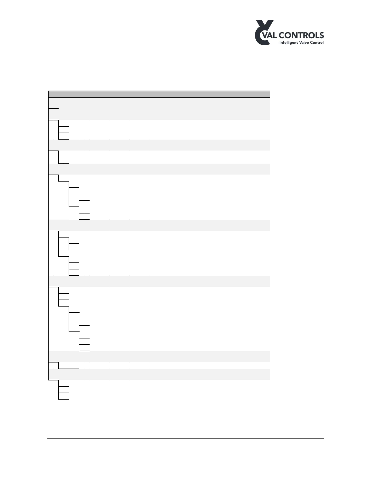
5.4 Menu
The menu consists of three submenus: Basic, Advanced and Pump control. In the basic menu some
basic control parameters can be changed. The positioner is still in service while these changes are
made. In the advanced menu, more advanced parameters can be changed. These parameters will
change how the positioner is working and the positioner will stop regulating while changing settings
in this menu.
Menu changes will not take effect until the user exits the menu and confirms the changes.
Menu Description
1.
Basic Basic control settings
2.
Advanced Advanced control settings
3.
Pump control Pump control settings
Page 15
DHP-UM-020
Val Controls A/S • Limfjordsvej 3 • DK-6715 Esbjerg N • Tel. +45 7547 0600 • Fax +45 7547 0611
[email protected] • www.valcontrols.com
Revision: 12
15/38
5.4.1 Basic menu
Basic menu structure.
Basic Default Reset Description
1 Deadband 1.0 B A Acceptable deviation from setpoint in percentage
2
Flow curve
Choice of flow curve
1 Linear √ B A Linear flow curve
2 Equal pct. 50:1 Equal percentage 50:1 flow curve
3 Custom Custom flow curve
3 Valve action Valve action
1 Direct √ B A Valve opens with increasing setpoint value
2 Reverse Valve closes with increasing setpoint value
4 Regulator functions Special function on how the positioner works
1 End settings Settings when the setpoint signal is 0% or 100%
1 Hold at open Function at 100%
1 Status Off B A Timer starts at 100%
2 Time 5 B A Time before positioner goes to stay-put
2 Hold at close Function at 0%
1 Status Off B A Timer starts at 0%
2 Time 5 B A Time before positioner goes to stay-put
5 Transmitter Transmitter settings
1 Transmitter action Transmitter action
1 Direct √ B A 0% flow = 4mA
2 Reverse 0% flow = 20mA
2 Transmitter fail position Transmitter fail
1
None
√ B A During a failure will the transmitter show the position
2 3.5 mA During failure the transmitter will be 3.5mA
3 21.5 mA During failure the transmitter will be 21.5mA
6 Display Display settings
1 Display light Off B A Controlling the diplay light
2 Contrast 5 B A Controlling the diplay contrast
3. Frontpage Configure the frontpage
1 Valve position B A Selcet who to display the position of the valve
1 Percent √ Show valve position in percent
2 Degree Show valve position in degree
2 Configuration Configuration for for the frontpage
1 Action Direct B A Set the direction of the valve position on the frontpage
2 Degree min
0°
B A Degree at 0%
3 Degree max 90° B A Degree at 100%
7 Status indicators Status indicators
1 Status On/Off Enable status indicators
8
MT control
Magnetic touch control
1 Status On/Off Enable MT control
2 Auto lock status On/Off Enable auto lock for MT control
3 Auto lock time 1 min Set the auto lock time
Page 16

DHP-UM-020
Val Controls A/S • Limfjordsvej 3 • DK-6715 Esbjerg N • Tel. +45 7547 0600 • Fax +45 7547 0611
[email protected] • www.valcontrols.com
Revision: 12
16/38
Deadband
The deadband can be manual altered from the user menu. The standard adjustment is 1% but this
value can be changed from 0.1 to 10 %.
Note: The deadband is on the position of the valve - not the flow!
If the deadband is set to e.g. 5% the valve positioner will regulate with a set point accuracy of +/- 5
% and stay there until the position feedback is bigger than 5 %.
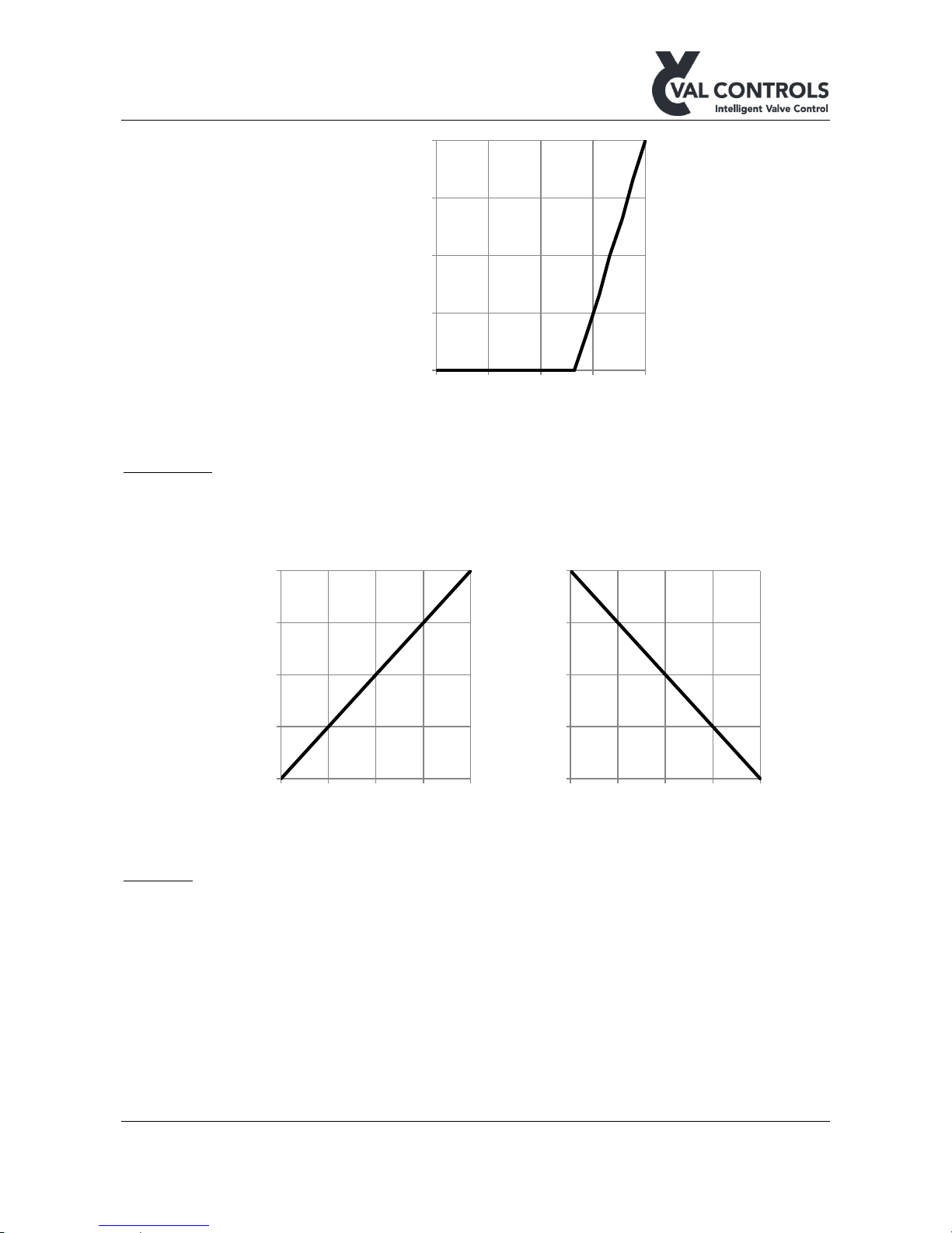
Flow curve
The valve characteristic expresses the flow percent through a valve at different opening angles. To
obtain an accurate regulation of the flow media it is important to choose a valve characteristic that
is identical with the one for the valve used.
Linear valve characteristic
The flow through the valve is proportional with the travel of the valve. The linear valvecharacteristic can be chosen from the user menu.
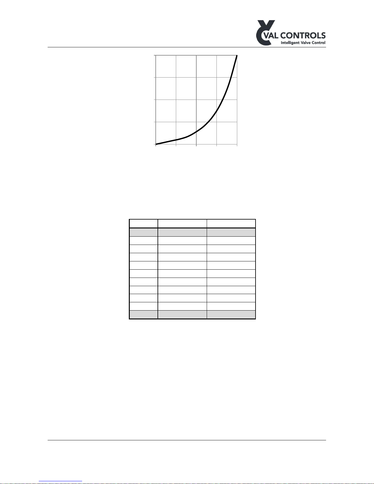
Equal Percentage 50:1
The flow through the valve rises in the last part of the curve. The equal percentage valve
characteristic can be chosen from the user menu.
0
25
50
75
100
0 25 50 75 100
Flow - %
Travel - %
Page 17
DHP-UM-020
Val Controls A/S • Limfjordsvej 3 • DK-6715 Esbjerg N • Tel. +45 7547 0600 • Fax +45 7547 0611
[email protected] • www.valcontrols.com
Revision: 12
17/38
Custom curve
The positioner offers the user to define his own valve characteristic from the keyboard. This option
makes it possible to use a wide range of valves and still be able to obtain an accurate regulation.
The positioner needs 11 reference points to linearize an arbitrary valve characteristic. Point 0 and
point 10 cannot be entered as they must be (0%, 0%) and (100%, 100%).
Point
Travel %
Flow %
0
0
0 1 66
0 2 72
16 3 78
33 4 83
50 5 89
66 6 94
83 7 100
100 8 100
100 9 100
100
10
100
100
When the points describing the flow curve are keyed in, the valve positioner will linearize the flow
curve.
0
25
50
75
100
0 25 50 75 100
Flow - %
Travel - %
Page 18
DHP-UM-020
Val Controls A/S • Limfjordsvej 3 • DK-6715 Esbjerg N • Tel. +45 7547 0600 • Fax +45 7547 0611
[email protected] • www.valcontrols.com
Revision: 12
18/38
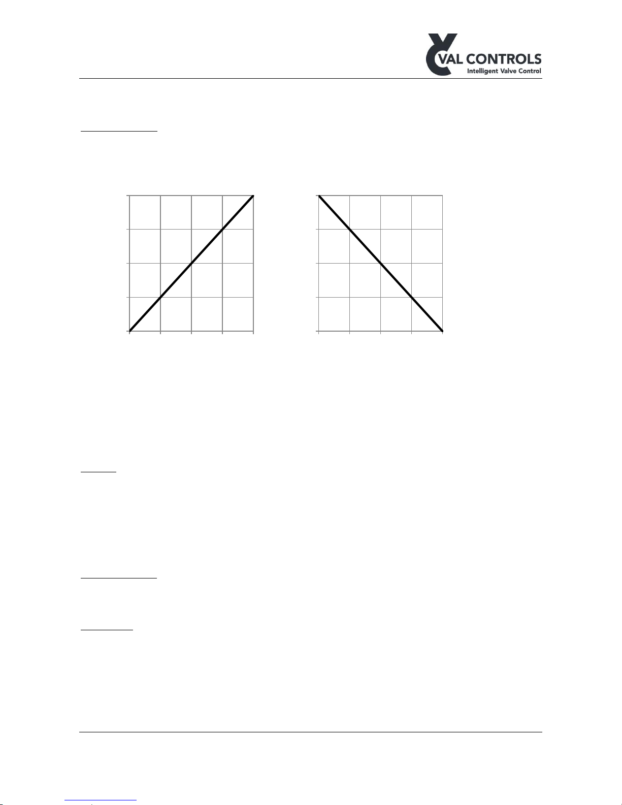
Valve action
Menu to select the Control loop to be Direct or Reverse.
• Direct : Valve opens with increasing set point value
• Reverse : Valve closes with increasing set point value
Regulator
Menu to set whether the regulator should keep opening or closing when within the deadband of 0%
and 100%
End settings
• Hold at Open:
o Status:
▪ Off: Never hold
▪ On: Hold after the number of seconds specified in the next menu
o Time: 0-30 sec. Do not have any effect if Status is Off
• Hold at Open:
o Status:
▪ Off: Never hold
0
25
50
75
100
0 25 50 75 100
Flow - %
Travel - %
0
25
50
75
100
4 8 12 16 20
Flow - %
Control loop - mA
0
25
50
75
100
4 8 12 16 20
Flow - %
Control loop - mA
Page 19
DHP-UM-020
Val Controls A/S • Limfjordsvej 3 • DK-6715 Esbjerg N • Tel. +45 7547 0600 • Fax +45 7547 0611
[email protected] • www.valcontrols.com
Revision: 12
19/38
▪ On: Hold after the number of seconds specified in the next menu
o Time: 0-30 sec. Do not have any effect if Status is Off
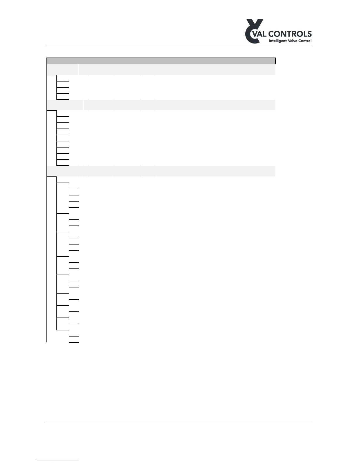
Transmitter loop
Menu to select the Transmitter loop to be Direct or Reverse.
• Direct : 0% flow = 4mA
• Reverse : 0% flow = 20mA
The transmitter loop will go into an error position when there is an error in the error log. It is
possible to choose between none and two positions:
• None
• 3.5mA +/- 0.2mA
• 21.5mA +/- 0.2mA
Display
• In this menu it is possible to turn the display light on, off or set it to automatic. When set on
automatic the display light will turn on when using the keyboard and turn off after 5 min.
not using the keyboard.
• The contrast level of the display can be adjusted.
• The direction of the position shown on the front page can be reversed.
Status indicators
• Enable the extra status indicators on models that have these
MT control
• Status: Enable MT control on models that have that
• Auto lock status: Enable the auto lock function
• Auto lock time: Ste the auto lock time
0
25
50
75
100
4 8 12 16 20
Flow - %
Transmitter loop - mA
0
25
50
75
100
4 8 12 16 20
Flow - %
Transmitter loop - mA
Page 20
DHP-UM-020
Val Controls A/S • Limfjordsvej 3 • DK-6715 Esbjerg N • Tel. +45 7547 0600 • Fax +45 7547 0611
[email protected] • www.valcontrols.com
Revision: 12
20/38
5.4.2 Advanced menu
Advanced menu Default Reset Description
1
Manual Control
Manual control of positioner.
1
Setpoint
Manual control of set point
2 Actuator Manual control of control valves
3 Actuator pulse Manual control of control valves using pulses only
4 Control valves Manual control of individual control valves
2 Signal Calibration Calibration of signals to control room
1 Control loop Calibration of 4-20 mA control signal
2 Transmitter loop Calibration of 4-20 mA transmitter signal
3 Position loop Calibration of 4-20 mA position loop
4 AI2 Calibration of 4-20 mA analogue input 1
5 AI3 Calibration of 4-20 mA analogue input 2
6 AI4 Calibration of 4-20 mA analogue input 3
7 AI5 Calibration of 4-20 mA analogue input 4
8 AO1 Calibration of 4-20 mA analogue output 1
9 AO2 Calibration of 4-20 mA analogue output 2
3 Configuration Configuration of in- and outputs
1 Valve function Configuration of valve control
1
Open
Not used A Menu to select valve position to open actuator
2 Close Not used A Menu to select valve position to close actuator
3 Stay-put Not used A Menu to select valve position to keep current actuator position
4 Fail position Off A Menu to select valve position at fail position
2 Position feedback Position feedback input
1 Position sensor A Potentiometer input
2 Position loop √ 4-20mA input
3 End position Configuration of endposition signal
1 Output signal 0% Not used A Select output which is active at 0%
2 Output signal 100% Not used A Select output which is active at 100%
3 Deadband 0.5% A Deadband for endpoint signal
4 Off/Local A Configure off/local signal
1 Off signal Not used A Select off signal input
2 Local signal Not used A Select local signal input
5 Man. valve control Configure the manaul control when in local mode
1 Open signal Not used A Select input to open valve
2 Close signal Not used A Select input to close valve
6 Emergency shutdown Configure Emergency shutdown
1 Input signal Not used A Select input to ESD signal
7 Error signal Configure error signal
1 Output signal Not used A Select output port for error signal
8 Ok signal Configure ok signal
1 Output signal Not used A Select output port for ok signal
9 Linear correction Calibrate the linearity of the position feedback
1 Status Enable the linear correction
2 Calibrate Perform the linear calibration
Page 21
DHP-UM-020
Val Controls A/S • Limfjordsvej 3 • DK-6715 Esbjerg N • Tel. +45 7547 0600 • Fax +45 7547 0611
[email protected] • www.valcontrols.com
Revision: 12
21/38
Advanced menu Default Reset Description
4 Control Parameters Control parameters for the regulator
1 Hysteresis 0.5% A Hysteresis around the dead band
2 Pos. ADC 1st end 0 A ADC value of first endpoint
3 Pos. ADC 2nd end 65535 A ADC value of second endpoint
4 Open on-time 100 A On-time when pulsing towards open
5
Open off-time
100 A Off-time when pulsing towards open
6 Close on-time 100 A On-time when pulsing towards close
7
Close off-time
100 A Off-time when pulsing towards close
8 Pulse open dist. 2% A The distance before the SP where the regulator is pulsing
9 Pulse close dist. 2% A The distance before the SP where the regulator is pulsing
5 Reset Resetting of positioner
1 Basic reset Resets all marked with B
2 Advanced reset Resets all marked with A
Manual control
In manual control it is possible to control the positioner manually in 4 different modes:
• Set point: The set point can be set and changed in different steps (1%, 10% and 25%).
• Useful if it is not possible no control loop is connected or the control loop signal cannot be
controlled.
• Actuator: The actuator can be opened and closed using the buttons. When no button is
pressed is the positioner in stay put mode.
• Useful to check whether open and close are set correctly and to check if the system can hold
the position in stay put mode.
• Actuator pulse: Similar to the Actuator function except that the positioner is pulsing.
• Control valves: Valve 1 and Valve 2 output can be controlled individually. Useful to find the
right settings for open, close and stay put of the control valves.
Signal calibration
In this menu is it possible to calibrate the analogue in- and out-puts.
Configuration
In configuration the user can change the setup of the positioner.
• Valve function: Configures how the valves operate during
o Open
o Close
o Stay-put
o Fail position: Only applicable for outputs which are used for open, close and stay-put
• Position feedback: Configures which input that is used for position feedback, either a
position sensor or a position loop.
• End position indicator: Lights an indicator when the actuator is at 0% or 100%. This
function has an adjustable deadband.
• Off/local selector: These inputs can be used to set the positioner in off or local mode
o Off: The valve will go to the fail position and the pump is off
o Local: The system is in manual and can be controlled using open and close buttons,
defined under manual valve control.
o Remote (Default): The system is controlled by control loop or communication
protocol.
Page 22

DHP-UM-020
Val Controls A/S • Limfjordsvej 3 • DK-6715 Esbjerg N • Tel. +45 7547 0600 • Fax +45 7547 0611
[email protected] • www.valcontrols.com
Revision: 12
22/38
• Manual valve control: Open and close function for connecting two buttons for use to manual
operate the valve when the selector is set to local.
• Emergency shutdown: De-energizes all the outputs used to control the solenoid valves and
turns off the pump. Error 301 will appear in the error log.
• Error signal: The signal is active when there is an error in the error log
• Ok signal: The signal is active when there is no errors in the error log
• Stepping: Software stepping functionality
o Status: Turn the stepping function on and off
o Fail step:
▪ Off: Set valve outputs to the fail position
▪ Open: Pulse to the open position
▪ Close: Pulse to the close position
o Open off-time ext.: Extra time for pulse off times when opening
o Close off-time ext.: Extra time for pulse off times when closing
o Open end pulses: Number of extra pulses to open the valve completely
o Close end pulses: Number of extra pulses to close the valve completely
• Linear correction: Calibrate the position feedback at 25%, 50% and 75 %. This calibration
will be lost at every endpoint calibration and auto calibration.
Control parameters
This menu shall only be used by Val Controls certified personal. For more information please
contact Val Controls
Reset
In this menu it is possible to reset the positioner back to default setting.
• Basic reset: Set the parameters in the basic menu to the default values.
• Erase config.: Set all configuration parameters to the default values including the
calibration. Analogue inputs and outputs calibration data is reset to factory defaults.
Page 23
DHP-UM-020
Val Controls A/S • Limfjordsvej 3 • DK-6715 Esbjerg N • Tel. +45 7547 0600 • Fax +45 7547 0611
[email protected] • www.valcontrols.com
Revision: 12
23/38
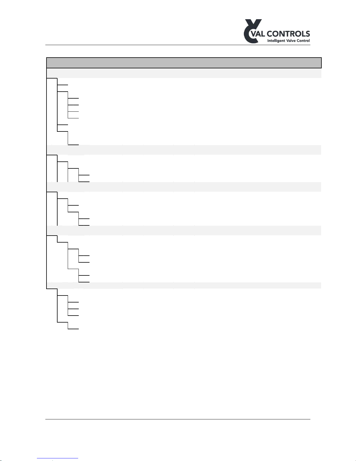
5.4.3 Pump Control menu
Pump Control Default Values Reset Description
1 Pump
1 Output None A Configure pump output signal
2 Controller The status of the pump controller
1 Always off √ A The pump is always off
2 Always on The pump is always on
3 Auto The pump controller is active
4 Manual Manual control the pump
3 Motor safety relay None A Select the input signal
4 Max running time Configure the max running time
1 Status Off On/off Status of the maximum running time function
2
Time
120 0-255 sec A Set the time the pump is active before a warning appears
2
Pressure
1
Loop
Configuration if using a pressure transmitter
1 Pump configuration Configure the levels which starts and stops the pump
1 Pump start 80 bar 0 - 500 bar A Start pump when pressure is below this value
2 Pump stop 120 bar 0 - 500 bar A Stop the pump when the pressure is above this value
3 Level
1
Loop
Configuration if using a level transmitter
1 Pump stop 100 mm 0-9999 mm A Stop the pump when the level is below this value
2 Loop configuration Configure the connected level transmitter
1 Loop 4mA value 0 mm 0-9999 mm A Level at 4mA
2 Loop 20mA value 700 mm 0-9999 mm A Level at 20mA
4 Temperature
1
Loop
Configuration if using a temperature transmitter
1 Pump stop high Pump stop high cofiguration
1 Status Off On/off Turn the pump stop high function on and off
2 Pump stop
80 °C
-200 - 850 °C A Stop the pump when the temperature is above this value
2 Pump stop low Pump stop low cofiguration
1 Status Off On/off Turn the pump stop low function on and off
2 Pump stop
-20 °C
-200 - 850 °C A Stop the pump when the temperature is below this value
5 Valve
1 Pump start
1 Valve open √ Start pump when valve opens
2 Valve close √ Start pump when valve closes
3 Valve stayput √ Start pump when valve goes to stayput
2 Pump stop
1 Delay 5 sec 0-240 sec Keeps the pump running after start command has ended
More settings are available through ValConnect.
Page 24
DHP-UM-020
Val Controls A/S • Limfjordsvej 3 • DK-6715 Esbjerg N • Tel. +45 7547 0600 • Fax +45 7547 0611
[email protected] • www.valcontrols.com
Revision: 12
24/38
Pump
Output: Configure which output is used to control the pump. Note that when an output is selected it
will not be available to control a solenoid valve.
Controller: The pump controller can be set to different modes.
• Always off: No power to the pump output
• Always on: Always power to the pump (except if motor safety relay is on or ESD is active)
• Auto: The pump is regulating depending on the hydraulic pressure, level and temperature.
• Manual: The pump can be controlled by a button on the positioner.
A sensor is not used if “None” is selected as the input signal.
Motor Safety Relay: Set the relay input port. When the port is disconnected the motor will stop
running.
Max Running Time: When the motor has been running for the specified period will an entry be
made in the error log. To remove this error the motor must stop and the timer is reset.
Pressure
Input signal: Configure which of the analogue or digital inputs that are used as the pressure signal.
That can be either an analogue loop input or digital input from two switches. By setting the input
signal to “None” the pump controller will not use pressure to determine if the pump should run or
not.
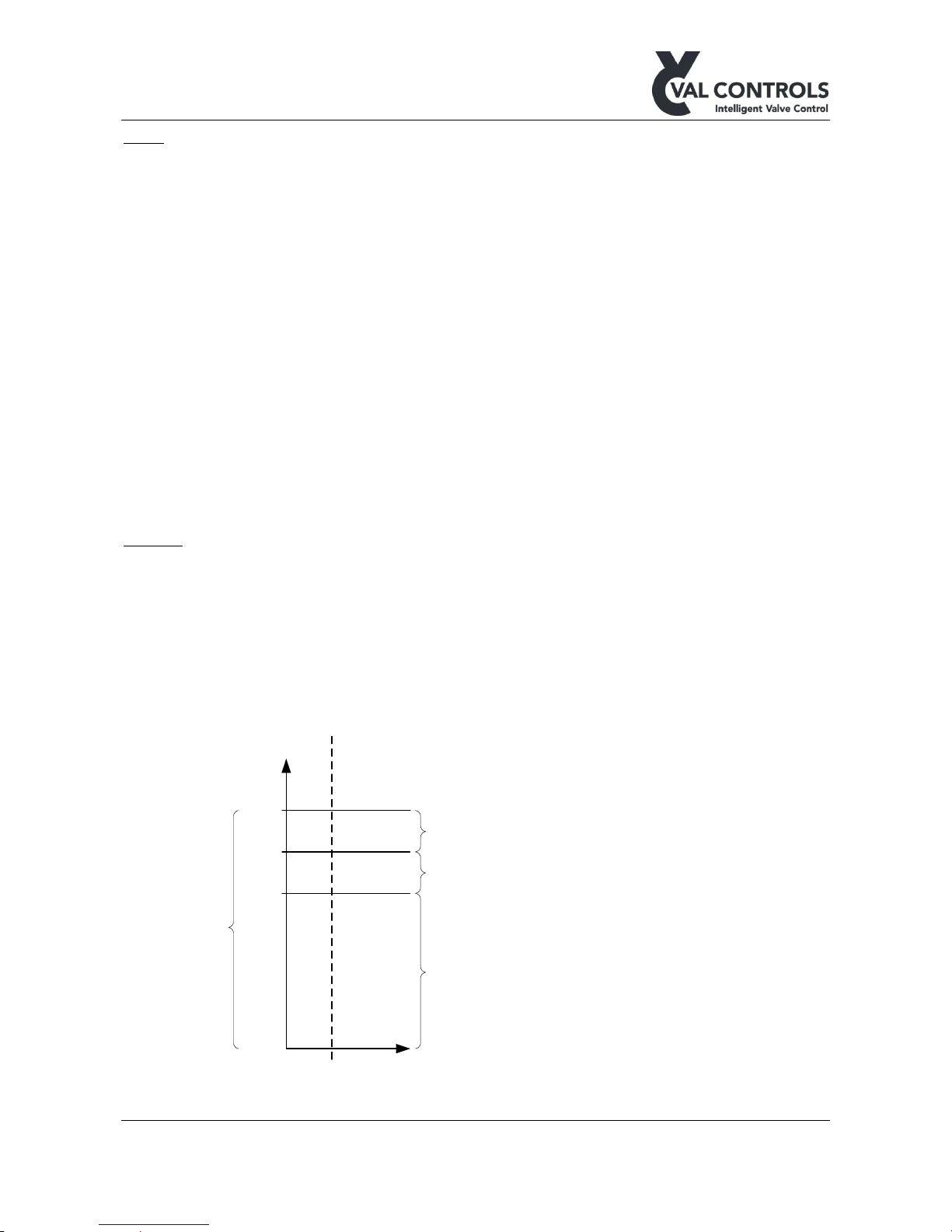
Loop: If a loop input is selected as the input signal the user must configure at which pressure the
pump must start and stop.
The pressure returned from the sensor at 4mA and 20mA must be entered into the positioner.
150
bar
120
80
0
Start pump
Stop pump
Sensor range
Pressure operating range
High
Low
Switch (NO)Loop
Page 25

DHP-UM-020
Val Controls A/S • Limfjordsvej 3 • DK-6715 Esbjerg N • Tel. +45 7547 0600 • Fax +45 7547 0611
[email protected] • www.valcontrols.com
Revision: 12
25/38
Switch: If pressure switches is used, then the user must select whether they are normally open or
normally closed switches.
Level
Input signal: Configure which of the analogue or digital inputs that is used as the level signal. That
can be either an analogue loop input or digital input from a switch. By setting the input signal to
“None” the pump controller will not use level to determine if the pump should run or not.
Loop: If a loop input is selected as the input signal the user must configure at which level the pump
must stop.
The levels returned from the sensor at 4mA and 20mA must be configured in the positioner.
There is a delay of 10 sec of the signals to secure stability.
Temperature
Input signal: Configure which of the analogue or digital inputs that is used as the temperature
signal. That can be either an analogue loop input or digital input from a switch. By setting the input
signal to “None” the pump controller will not use temperature to determine if the pump should run
or not.
Loop: If a loop input is selected as the input signal the user must configure at which temperature the
pump must stop.
The temperature returned from the sensor at 4mA and 20mA must be configured in the positioner.
There is a delay of 10 sec to secure stability.
Page 26

DHP-UM-020
Val Controls A/S • Limfjordsvej 3 • DK-6715 Esbjerg N • Tel. +45 7547 0600 • Fax +45 7547 0611
[email protected] • www.valcontrols.com
Revision: 12
26/38
6 Regulators
6.1 Electronic stepping
Electronic stepping is used to operate a standard double acting or spring return actuator in a
stepping mode replicating the functionality of a stepping actuator.
• Set the Regulator type to “Electronic stepping” through ValConnect
• Perform an auto calibration
• Set the extra “Off-times” to increase the duration of the stroke
o Open off-time extra
o Close off-time extra
• Fail step: Set desired action in case of loss of control loop or position signal
• Open end pulses: Number of pulses after the position has reached full open
• Close end pulses: Number of pulses after the position has reached full close
6.2 Mechanical stepping
The configuration of a mechanical stepping is to be done through ValConnect. The recommended
settings when setting up a IHP24 with a stepping actuator is:
• Regulator type: Mechanical stepping
• Dead band: 2 %
• Open on-time: 5 sec
• Close on-time: 5 sec
• Open off-time: 5 sec
• Close off-time: 5 sec
The following parameters can be used to tune the functionality of the regulator
• Fail step: Set desired action in case of loss of control loop or position signal
• Open end pulses: Number of pulses after the position has reached full open
• Close end pulses: Number of pulses after the position has reached full close
6.3 Proportional
Configuration
In configuration the user can change the setup of the positioner.
• Valve function: Configures how the valves operate during open, close and stay-put. The
proportional output can be configured in three ways.
o AO1 : 4 mA is full close, 12mA is stay-put and 20mA is full open.
o AO2 : 4 mA is full close, 12mA is stay-put and 20mA is full open.
o AO1 and AO2 AO1= 20mA, AO2= 4mA is full close.
AO1= 4mA, AO2 = 20mA is full open.
AO1= 4mA, AO2= 4mA is stay-put.
Page 27

DHP-UM-020
Val Controls A/S • Limfjordsvej 3 • DK-6715 Esbjerg N • Tel. +45 7547 0600 • Fax +45 7547 0611
[email protected] • www.valcontrols.com
Revision: 12
27/38
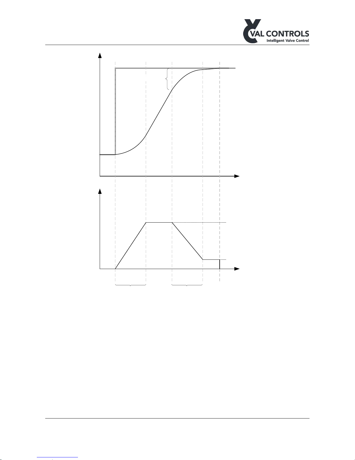
• Stay-put position: Tune the 12mA output when only one AO is used. Used for proportional
valves that has a spool which is out of the centre.
• Propor. fail pos: Set the fail position of the analogue output.
o 4mA
o 12mA (Default)
o 20mA
Control parameters
• Hysteresis: The hysteresis at the setpoint
• Pos. ADC 1st end: Fine adjust the 1st end point
• Pos. ADC 2nd end: Fine adjust the 2nd end point
The following parameters can only be accessed through ValConnect.
• Slow speed open: Set the minimum speed when opening
• Slow speed close: Set the minimum speed when opening
• Speed open: Set the normal speed when opening
• Speed close: Set the normal speed when closing
• Acceleration open: Set the acceleration time when opening
• Acceleration close: Set the acceleration time when closing
• Deceleration open: Set the deceleration time when opening
• Deceleration close: Set the deceleration time when closing
• Slow open dist: Set the distance before the set point that deceleration will start when
opening
• Slow close dist: Set the distance before the set point that deceleration will start when closing
Page 28
DHP-UM-020
Val Controls A/S • Limfjordsvej 3 • DK-6715 Esbjerg N • Tel. +45 7547 0600 • Fax +45 7547 0611
[email protected] • www.valcontrols.com
Revision: 12
28/38
Acceleration time
Slow speed
Normal speed
Slow speed dist
Time (sec)
Time (sec)
Speed (%)
Position (%)
Set point
Actuator position
Deceleration time
0%
Page 29
DHP-UM-020
Val Controls A/S • Limfjordsvej 3 • DK-6715 Esbjerg N • Tel. +45 7547 0600 • Fax +45 7547 0611
[email protected] • www.valcontrols.com
Revision: 12
29/38
7 Error no.
7.1 Mounting and settings
No. 101
Solenoids are not configured
Description
The Valve Function has not been configured in the menu
Trouble shooting
Configure the Valve Function in the advanced menu (3.1)
Consequence
The positioner outputs goes to their fail position.
No. 102
Potentiometer is not connected
Description
The potentiometer has been selected as the position feedback signal, but there
is not connected a potentiometer to the positioner.
Trouble shooting
Connect a potentiometer to the positioner
Or
Change the position feedback signal to position loop in the advanced menu
(3.2)
Consequence
The positioner outputs goes to their fail position.
No. 103
Position loop is not connected
Description
The position loop has been selected as the position feedback signal, but there
is not connected a signal to the positioner.
Trouble shooting
Connect a loop signal to the positioner
Or
Change the position feedback signal to potentiometer in the advanced menu
(3.2)
Consequence
The positioner outputs goes to their fail position.
No. 104
Control loop is not connected
Description
A control loop has not been connected to the positioner
Trouble shooting
Connect a control loop to the positioner
Consequence
The positioner outputs goes to their fail position.
Page 30
DHP-UM-020
Val Controls A/S • Limfjordsvej 3 • DK-6715 Esbjerg N • Tel. +45 7547 0600 • Fax +45 7547 0611
[email protected] • www.valcontrols.com
Revision: 12
30/38
No. 105
Control loop is not calibrated
Description
The control loop is not calibrated
Trouble shooting
Calibrate the control loop from the advanced menu (2.1)
No. 106
Transmitter loop is not calibrated
Description
The transmitter loop is not calibrated
Trouble shooting
Calibrate the transmitter loop from the advanced menu (2.2)
No. 108
Position loop is not calibrated
Description
The position loop is not calibrated
Trouble shooting
Calibrate the position loop from the advanced menu (2.3)
No. 109
Analogue input loop 2 is not calibrated
Description
The analogue input loop 2 is not calibrated
Trouble shooting
Calibrate the analogue input loop 2 from the advanced menu (2.4)
No. 110
Analogue input loop 3 is not calibrated
Description
The analogue input loop 3 is not calibrated
Trouble shooting
Calibrate the analogue input loop 3 from the advanced menu (2.5)
No. 111
Analogue input loop 4 is not calibrated
Description
The analogue input loop 4 is not calibrated
Trouble shooting
Calibrate the analogue input loop 4 from the advanced menu (2.6)
No. 112
Analogue input loop 5 is not calibrated
Description
The analogue input loop 5 is not calibrated
Trouble shooting
Calibrate the analogue input loop5 from the advanced menu (2.7)
No. 113
Analogue output loop 1 is not calibrated
Description
The analogue output loop 1 is not calibrated
Page 31
DHP-UM-020
Val Controls A/S • Limfjordsvej 3 • DK-6715 Esbjerg N • Tel. +45 7547 0600 • Fax +45 7547 0611
[email protected] • www.valcontrols.com
Revision: 12
31/38
Trouble shooting
Calibrate the analogue output loop 1 from the advanced menu (2.8)
No. 114
Analogue output loop 2 is not calibrated
Description
The analogue output loop 2 is not calibrated
Only applicable when using the proportional regulator
Trouble shooting
Calibrate the analogue output loop 2 from the advanced menu (2.9)
No. 120
Proportional output is not configured
Description
The proportional output signal has not been configured
Only applicable when using the proportional regulator
Trouble shooting
Configure the proportional output signal in the advanced menu (3.1.4)
No. 130
SP has not been set
Description
The SP has not been set through Modbus or Foundation Fieldbus
Only applicable for Modbus or Foundation Fieldbus version
Trouble shooting
• Send a SP to the unit.
• Contact Val Controls
Consequence
The positioner outputs goes to their fail position.
Page 32
DHP-UM-020
Val Controls A/S • Limfjordsvej 3 • DK-6715 Esbjerg N • Tel. +45 7547 0600 • Fax +45 7547 0611
[email protected] • www.valcontrols.com
Revision: 12
32/38
7.2 Calibration
No. 201
Not Calibrated!
Description
The positioner is not calibrated
Trouble shooting
Calibrate the positioner
No. 202
Calibrated w. error. Using old values!
Description
The last calibration failed and the positioner is using the parameters from the
previous calibration.
Trouble shooting
Investigate the Error log to find the reason to why the calibration failed.
No. 203
Too few ADC points
Description
The measured travel is not large enough
Trouble shooting
Increase the travel
Check that the requirements for operating area (3.4 Electrical specifications)
for the position sensor or position loop are used.
No. 204
No movement or too large actuator
Description
The positioner has not detected any movement
Trouble shooting
Movement is confirmed visually:
• The actuator is very slow moving. Use manual calibration without auto
tuning
• Check that the position feedback is connected correct
No movement:
• Check that the solenoids are configured correct
• Check the hydraulic system
No. 205
Travel time too long. Actuator is too big
Description
The travel time is larger than 120 sec
Trouble shooting
Use manual calibration without auto tuning
Page 33
DHP-UM-020
Val Controls A/S • Limfjordsvej 3 • DK-6715 Esbjerg N • Tel. +45 7547 0600 • Fax +45 7547 0611
[email protected] • www.valcontrols.com
Revision: 12
33/38
No. 206
Sensor signal is too noisy
Description
The sensor signal is too noisy, even if the deadband has been set to 10%
Trouble shooting
• Improve signal quality
• Increase the travel
No. 207
Calibration timeout
Description
A timeout occurred during the calibration
Trouble shooting
The system behaves in an unexpected way.
• Slow down the system
Restart the calibration
No. 208
Hold test failed
Description
The positioner is not able to hold the actuator at a 50%
Trouble shooting
• Check solenoid settings
• Check for leakages in the hydraulic system
• If the system is fast (travel time <3). Slow system down
7.3 External connections
No. 301
ESD signal
Description
The ESD signal is low
Trouble shooting
• Restore ESD signal
• Disable ESD functionality in the advanced menu
Page 34

DHP-UM-020
Val Controls A/S • Limfjordsvej 3 • DK-6715 Esbjerg N • Tel. +45 7547 0600 • Fax +45 7547 0611
[email protected] • www.valcontrols.com
Revision: 12
34/38
7.4 Pump unit
No. 601
Pump control. Low level
Description
The measured level is below the specified value.
Trouble shooting
Check the oil level in the tank. If oil level is okay, then check the following
items in the menu.
• Adjust pump stop level (3.3.2.1)
• Adjust loop configuration (3.3.2.2)
• Calibrate analogue input (2.2.3-6)
No. 602
Pump control. High temperature
Description
The measured temperature is above the specified values.
Trouble shooting
• Check the temperature of the oil
• Increase high temperature limit
No. 603
Pump control. Low pressure
Description
The pressure error input has been disconnected
Trouble shooting
A pressure error has been signalled to the positioner.
• Activate the override function (Digital input) to force the pump to run
No. 604
Pump control. Low Low pressure
Description
Low Low pressure has been detected
Trouble shooting
A pressure error has been signalled to the positioner.
• Increase the pressure
• Decrease the Low Low pressure limit
Page 35
DHP-UM-020
Val Controls A/S • Limfjordsvej 3 • DK-6715 Esbjerg N • Tel. +45 7547 0600 • Fax +45 7547 0611
[email protected] • www.valcontrols.com
Revision: 12
35/38
No. 605
Pump control. High high pressure
Description
High High pressure has been detected
Trouble shooting
A pressure error has been signalled to the positioner.
• Decrease the pressure
• Increase the High High pressure limit
No. 607
Pump control. Low temperature
Description
The measured temperature is below or below the specified values.
Trouble shooting
• Check the temperature of the oil
• Decrease low temperature limit
No. 610
Pump control. Motor safety relay
Description
The motor protection relay
Trouble shooting
Check the motor safety relay and the connection to the IHP.
Page 36
DHP-UM-020
Val Controls A/S • Limfjordsvej 3 • DK-6715 Esbjerg N • Tel. +45 7547 0600 • Fax +45 7547 0611
[email protected] • www.valcontrols.com
Revision: 12
36/38
No. 611
Pump control. Max running time
Description
The motor has been running for too long.
Trouble shooting
Investigate why the motor is still running.
Or increase the max running time in the menu
• Max running time(3.4)
7.5 Communication
No. 8xx
Communication error
Description
A communication error has occurred
Trouble shooting
See separate communication user manual.
7.6 Internal errors
No. 9xx
Internal Error contact support
Description
An internal error has occurred
Trouble shooting
Contact Val Controls A/S and give the following information:
• Product type
• Software version
• Error number
• How did the error occur
Page 37

DHP-UM-020
Val Controls A/S • Limfjordsvej 3 • DK-6715 Esbjerg N • Tel. +45 7547 0600 • Fax +45 7547 0611
[email protected] • www.valcontrols.com
Revision: 12
37/38
8 Software revision list
Version 3.13.00
• New functions
o Stepping actuators can be controlled
o Update to identification menu, show model no and serial no.
Version 3.13.01
• New function
o Fast detection of lost control loop
• Minor improvements
Version 3.13.02
• Minor improvements
Version 3.13.03
• New function
o Delayed detection of reconnected control loop
Version 3.14.00
• Foundation fieldbus improved
Version 3.14.01
• Minor improvements
Version 3.15.00
• Digital inputs can be inverted
• Pump controller: DI is not set separately from AI.
• Pump controller: “One pressure” switch configuration is now possible
Version 3.15.01
• Minor improvements
Version 3.16.00
• Invert open/close led on front. Only available via ValConnect
Page 38

DHP-UM-020
Val Controls A/S • Limfjordsvej 3 • DK-6715 Esbjerg N • Tel. +45 7547 0600 • Fax +45 7547 0611
[email protected] • www.valcontrols.com
Revision: 12
38/38
Version 3.17.00
• MT locked LED on front functionality inverted. LED is ON when MT Control is unlocked.
• Advanced reset renamed to Erase config.
• Minor improvements
Version 3.17.01
• Minor improvements
Version 3.17.02
• Minor improvements
Version 3.17.03
• Minor improvements
Version 3.17.04
• Minor improvements
Version 3.17.05
• Proportional controller: Enable automatic calibration as automatic endpoint calibration from
the display.
 Loading...