

Page 1
V-WMCR Wireless Repeater Installation Manual (Rev 1.04)
Table of Contents
MOUNTING
Mounting Diagram…………………………….…….…………………………… Page 2
WIRING INFORMATION
Wiring Information……………..………………………………………………… Page 3
JUMPER SETTINGS
Setting V-WMCR as a Repeater or Transmitter…………………………………. Page 4
V-WMCR as a Transmitter
LED Indicators for Valcom Digital Correction……………………….
Valcom Digital Correction to V-WMCR……………………………..
FREQUENTL Y ASKED QUESTIONS
V-WMCR Frequently Asked Questions………………………………………..… Page 8
Page 5
Page 6-7
TROUBLESHOOTING
V-WMCR Troubleshooting….…………………………………………………… Page 8
FCC INFORMATION
FCC Wants You To Know……………………………………………………….. Page 9
Valcom 5614 Hollins Road Roanoke, VA 24019 Phone: (540) 563-2000 Fax: (540) 362-9800 www.valcom.com
Page 1
Page 2
V-WMCR Wireless Repeater Installation Manual (Rev 1.04)
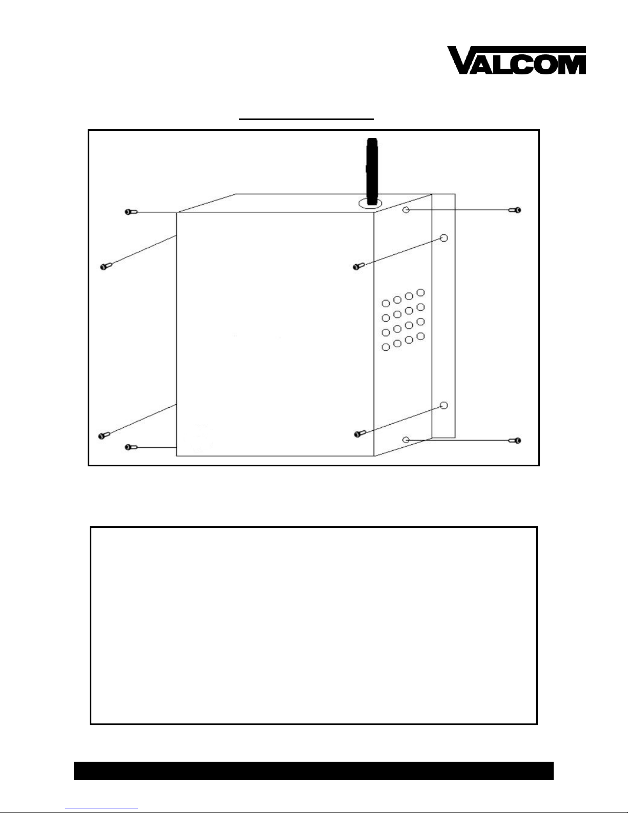
Mounting Diagram
INSTRUCTIONS
1. Find a location that will allow the repeater to transmit the signal in open
space. (hallway recommended)
2. Run the wiring through the knockouts and connect according to the wiring information.
3. Tighten all four (4) screws (6-32) on the front panel.
4. Line up the repeater in the desired mounting location and mark the
holes.
5. Mount anchors (not included) to where the holes were marked at in the
previous step.
6. Mount the repeater using four (4) screws (not included).
Valcom 5614 Hollins Road Roanoke, VA 24019 Phone: (540) 563-2000 Fax: (540) 362-9800 www.valcom.com
Page 2
Page 3
V-WMCR Wireless Repeater Installation Manual (Rev 1.04)
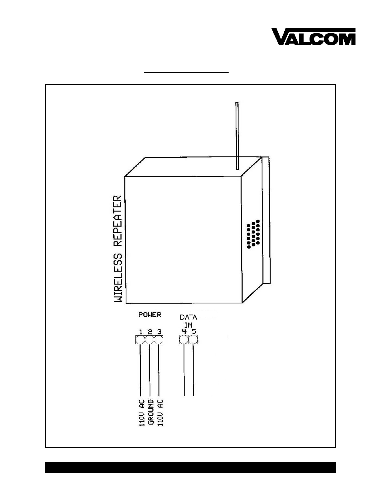
Wiring Information
Valcom 5614 Hollins Road Roanoke, VA 24019 Phone: (540) 563-2000 Fax: (540) 362-9800 www.valcom.com
Page 3
Page 4

V-WMCR Wireless Repeater Installation Manual (Rev 1.04)
Jumper Settings for the V-WMCR as a Repeater or Transmitter
1 2 3 4 5 6 7
Represents jumpers set as a repeater
Represents jumpers set as a transmitter
Valcom 5614 Hollins Road Roanoke, VA 24019 Phone: (540) 563-2000 Fax: (540) 362-9800 www.valcom.com
JP1 JP2
REPEATER
TRANSMITTER
REPEATER
TRANSMITTER
Page 4
Page 5

V-WMCR Wireless Repeater Installation Manual (Rev 1.04)
LED Indicators for Valcom Digital Correction to the V-WMCR
When Used as a Transmitter
LED Indicators
If the V-WMCR is receiving communication while in transmitter mode, the LEDs in the figure
shown above will flicker consistently with one another.
Valcom 5614 Hollins Road Roanoke, VA 24019 Phone: (540) 563-2000 Fax: (540) 362-9800 www.valcom.com
Page 5
Page 6

V-WMCR Wireless Repeater Installation Manual (Rev 1.04)
Valcom Digital Correction to the V-WMCR
V-GPS
When Used as a Transmitter
3 4
V-WMCR
5
4
* NOTE: When connecting the V-WMCR, the polarity must be correct to function correctly.
Page 6
Valcom 5614 Hollins Road Roanoke, VA 24019 Phone: (540) 563-2000 Fax: (540) 362-9800 www.valcom.com
Page 7

V-WMCR Wireless Repeater Installation Manual (Rev 1.04)
Valcom Digital Correction to the V-WMCR
When Used as a Transmitter
V-WMC
19
20
V-WMCR
4 5
* NOTE: When connecting the V-WMCR, the polarity must be correct to function correctly.
Page 7
Valcom 5614 Hollins Road Roanoke, VA 24019 Phone: (540) 563-2000 Fax: (540) 362-9800 www.valcom.com
Page 8

V-WMCR Wireless Repeater Installation Manual (Rev 1.04)
Frequently Asked Questions
Where is the best location for the Repeater to be mounted?
Usually, the hallway is the best location because it is mostly open space in typical applications.
How far can the Repeater transmit the wireless signal?
The Repeater can transmit up to 2000 meters in open space.
Will the Repeater have interference from cordless or cellular phones?
No, because with Valcom’s innovative frequency-hopping technology, interference will not occur.
The repeater switches frequencies automatically when the receiver and transmitter is open, thus interference is avoided.
How do I know if the Repeater is receiving the wireless signal?
On the small circuit board standing vertical on the larger board, there are two LEDs. When the Repeater gets the wireless signal from the Transceiver, the LED to the left will flash one time.
Can analog wireless clocks be combined with digital wireless clocks?
The analog and digital wireless clocks are designed to work together, whether the clocks are running
on battery (analog wireless clock only), 24 volts or 110 volts.
My power source is 220 volts. Can the Repeater be powered on that voltage?
Yes, the Transceiver can work on 110 volts/60 Hz or 220 volts/50 Hz.
How do you make the Repeater a Transmitter?
With the repeater powered down, switch both jumpers from repeater to transmitter. Then connect
the Valcom digital output of any Valcom Master Clock to the Valcom Digital input on the repeater,
4 & 5.
The clocks aren’t receiving the signal. What should I do?
Make sure that the Repeater is in a place where the signal can be transmitted in open space.
What should I do if the Repeater is not powering up?
Measure the voltage between pins 1 & 3. The voltmeter should read 85 - 135 VAC between
the hot and the neutral.
Valcom 5614 Hollins Road Roanoke, VA 24019 Phone: (540) 563-2000 Fax: (540) 362-9800 www.valcom.com
Troubleshooting
Page 8
Page 9

V-WMCR Wireless Repeater Installation Manual (Rev 1.04)
FCC Wants You to Know
This equipment has been tested and found to comply with the limits for a Class B digital device, pursuant to Part 15 of the FCC rules. These limits are designed to provide reasonable
protection against harmful interference in a commercial installation. This equipment generates, uses and can radiate radio frequency energy and, if not installed and used in accordance
with the instructions, may cause harmful interference to radio communications. However,
there is no guarantee that interference will not occur in a particular installation. If this equipment does cause harmful interference to radio or television reception, which can be determined by turning the equipment off and on, the user is encouraged to try to correct the interference by one or more of the following measures:
a) Reorient or relocate the receiving antenna.
b) Increase the separation between the equipment and receiver.
c) Connect the equipment to an outlet on a circuit different
from which the receiver is connected.
d) Consult the dealer or an experienced radio/TV technician.
FCC WARNING
Modifications not expressly approved by the manufacturer could void the user authority to oper-
ate the equipment under FCC Rules.
Note: For precautionary measures, FCC recommends a distance of 10cm from the clock to constant human physical exposure.
Page 9
Valcom 5614 Hollins Road Roanoke, VA 24019 Phone: (540) 563-2000 Fax: (540) 362-9800 www.valcom.com
 Loading...