

Page 1
Issue 1
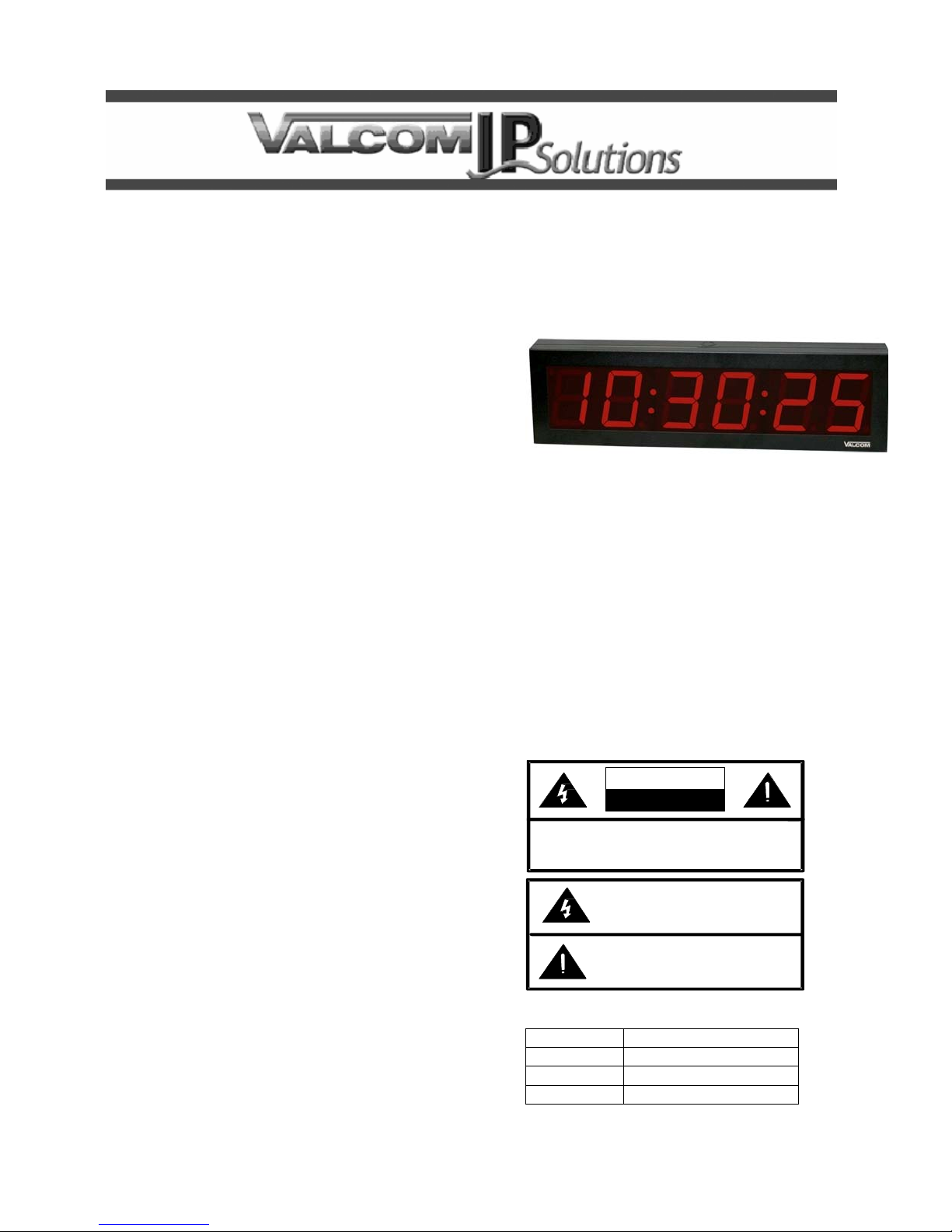
IP PoE Surface Mount Digital Clocks
VIP-D625, 6 Digit, 2.5” Display
VIP-D640, 6 Digit, 4.0” Display
INTRODUCTION
The VIP-D625 2.5 inch, 6 Digit Clock Display and
VIP-D640 4.0 inch, 6 Digit Clock Display enable
time indication, synchronization, and correction over
an IP-based LAN/WAN. This allows locating a clock
display anywhere on the network. Clock
synchronization is initiated via connection to a
factory preprogrammed time server. The enclosure
is made of steel with a durable powder coated
finish. The color of the enclosure can easily be
changed to match any décor. Power is provided to
the VIP-D625 and VIP-D640 via a Power over
Ethernet (PoE) switch meeting the 802.3af
specification.
SPECIFICATIONS
Features
• RJ-45 network connection
• Easy to read, high visibility Red 2.5” or 4.0”
digits display hours, minutes and seconds
• Selectable 12 or 24 hour format (jumper setting)
• 802.3af compatible
• High Efficiency
INSTALLATION
FCC Information
This equipment has been tested and found to
comply with the limits for a Class A digital
device, pursuant to Part 15 of the FCC Rules.
These limits are designed to provide reasonable
protection against harmful interference when
the equipment is operated in a commercial
environment. This equipment generates, uses
and can radiate radio frequency energy and if
not installed and used in accordance with the
instruction manual, may cause harmful
interference to radio communications.
Operation of this equipment in a residential area
may cause harmful interference in which case
the user will be required to correct the
interference at one’s own expense.
Issue 1
DIMENSIONS/WEIGHT
• VIP-D625 - 15.30” L x 3.00” W x 4.90” H
• Weight: 3.85 LBS.
• VIP-D640 - 24.50” L x 3.00” W x 6.75” H
• Weight: 6 LBS.
Nominal Power Requirements
6.9W via 802.3af PoE
Environment
Temperature: 0 to +40° C
Humidity: 0 to 85% non-precipitating
Precautionary Designations
CAUTION
RISK OF ELECTRIC SHOCK
DO NOT OPEN
CAUTION: To reduce the risk of electric shock,
Ref er serv icing to qua lified s ervice per sonne l.
Do not remove cover.
No user serviceable parts inside.
This symbol indicates that dangerous
voltage constituting a risk of electric
sho ck is pr esent wit hin this un it.
This symb ol indicates tha t there are
imp ortan t ope rating a nd main tenan ce
inst ructio ns in th e literat ure ac com panying
this unit.
Packing List
Qty. Item
1 VIP-D625 or VIP-D640
1 VSP Document
1 VIP Setup CD
1
Page 2
MOUNTING
Remove the side screws holding the mounting
plate/rear panel to the enclosure. Mount the plate to
the wall or a standard double-gang electrical box
using appropriate hardware such as #8 pan head
screws (not supplied). After making the required
connections, reattach the enclosure to the mounting
plate, rear panel.
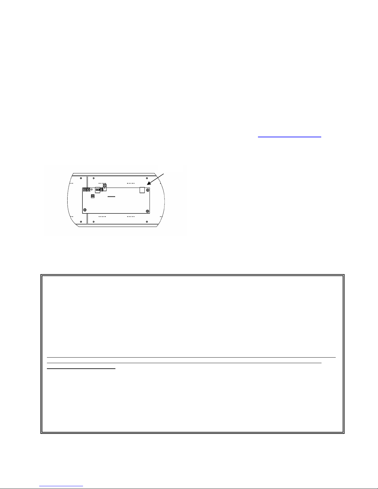
NETWORK CONNECTION
The VIP-D625 and VIP-D640 have one CAT-5
RJ-45 network connector on the rear panel.
See Figure 1. Connect a CAT-5 patch cable from
the VIP-D625 or VIP-D640 into an Ethernet switch.
If a PoE switch is not available, a PoE mid-span
injector may be used to supply power to the clocks.
RJ45
TECHNICAL ASSISTANCE
When trouble is reported, verify power is being
supplied to the unit and there are no broken
connections. If a spare unit is available, substitute a
spare unit for the suspected defective unit.
Assistance in troubleshooting is available from the
factory. Call (540) 563-2000 and press 1 for
Technical Support or via email at
support@valcom.com
When requesting assistance, you should include all
available information. It is strongly suggested that
you go to the web site and review the
documentation at http://www.valcom.com
.
Valcom equipment is not field-repairable. Valcom,
Inc. maintains service facilities in Roanoke, VA.
Should repairs be necessary, attach a tag to the
unit clearly stating your company name, address,
phone number, contact person and the nature of
the problem. Send the unit to:
Valcom, Inc.
Repair & Return Dept.
5614 Hollins Road
Roanoke, Va. 24019-5056
Figure 1. Connections (Back
VALCOM LIMITED WARRANTY
Valcom, Inc. warrants its products to be free from defects in materials and workmanship under conditions of normal use and service
for a period of one year from the date of shipment. The obligation under this warranty shall be limited to the replacement, repair or
refund of any such defective device within the warranty period, provided that:
1. inspection by Valcom, Inc. indicates the validity of the claim;
2. the defect is not the result of damage, misuse or negligence after the original shipment;
3 the product has not been altered in any way or repaired by others and that factory sealed units are unopened (a service
charge plus parts and labor will be applied to units defaced or physically damaged);
4. freight charges for the return of products to Valcom are prepaid;
5 all units ‘out of warranty’ are subject to a service charge. The service charge will cover minor repairs (major repairs will
be subject to addition charges for parts and labor).
This warranty is in lieu of and excludes all other warranties, expressed or implied, and in no event shall Valcom, Inc. be liable for any
anticipated profits, consequential damages, loss of time or other losses incurred by the buyer in connection with the purchase,
operation or use of the product.
This warranty specifically excludes damage incurred in shipment. In the event a product is received in damaged condition, the carrier
should be notified immediately. Claims for such damage should be filed with the carrier involved in accordance with the F.O.B. point.
Headquarters
Valcom, Inc.
5614 Hollins Road
Roanoke,Va 24019-5056
Phone: (540) 563-2000
Fax: (540) 362-9800
2
 Loading...