

Valcom VIP-801-IC Installation Manual
Issue 2
VIP-801-IC
®
InformaCast
Compliant
Network Audio Port
INSTALLATION
Mounting
The VIP-801-IC is designed for wall or table
mounting.
Table: Provided with the VIP-801-IC are four rubber
pads. Peel the pads from their carrier backing and
place at the four corners of the bottom of the unit.
Wall: Using the brackets and screws provided,
secure the VIP-801-IC to the wall.
Power Connections
The preferred method of powering a VIP-801-IC is
via a power over Ethernet switch meeting the
802.3af specification. If the rear panel barrel
connector is used for power, the preferred power
supply is a Valcom VIP-324D.
Make all required signal connections before
applying power to the unit. If powering via 802.3af
Power over Ethernet, make sure all signal
connections via the back panel are made then
connect the VIP-801-IC to the Ethernet switch.
If power is supplied via the barrel connector, make
sure all signal connections are secure. Attach the
unit to the network via the front panel RJ-45
Ethernet connector. Apply power by plugging the
power supply into the VIP-801-IC via the barrel
connector on the rear of the VIP-801-IC.
Network Connection
The VIP-801-IC has one RJ-45 network connector
on the front panel.
Use a standard Ethernet patch cable to connect the
VIP-801-IC to an Ethernet switch.
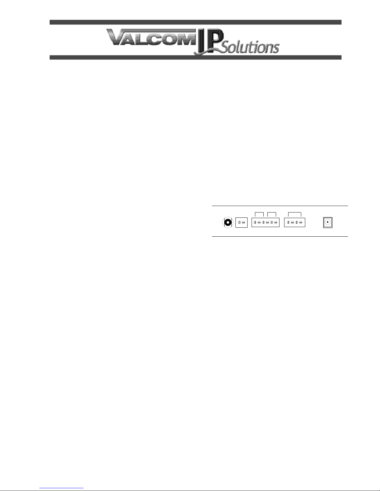
Signal Connections
The VIP-801-IC has 2 active signal connectors on
the rear panel:
2 Pin screw terminal for audio output
6 Pin screw terminal for relay connections
(Connectors AUX, K2, INPUTS are not used)
Audio Out: Typically connects to Self Amplified
Speakers or into an amplifier. AUX Input audio
mutes when Audio Out is receiving page audio.
Relay Channels: Access to the form C r elay is
provided via three screw terminals (on a six pin
screw terminal block) labeled K1. The common
contact is the middle terminal with the normally
closed (N.C) contact on the left and the normally
open (N.O.) contact on the right. Relay contacts
are rated for 1A @ 24VDC.
K2
AUDIOAUX
OUTIN AUDIO CC
K1
COM
N.O.
N.O.
N.C.
INPUTS
COM
N.C.
+24V DC
Rear View
Status Indicator Lights
The VIP-801-IC has 3 status indication lights on the
front panel:
STATUS: Flashes during normal operation and
solid during system startup.
LINK: Indicates a 100 Mbit Ethernet connection
when illuminated. A non-illuminated LINK LED
indicates a 10 Mbit connection or no network
connection.
ACT: Indicator flashes to indicate network activity.
Setup
The VIP-801-IC will automatically acquire an IP
address (using DHCP) and connect to the
InformaCast server when connected to the network
and powered up. Information specific to your
application will need to be programmed into the
InformaCast server. Refer to the InformaCast
documentation for further information.
1 947791

TECHNICAL ASSISTANCE
Assistance in troubleshooting is available from
the factory. Call (540) 563-2000 and press 1 for
Technical Support or via email at
support@valcom.com.
When requesting assistance, you should include
all available information. It is strongly suggested
that you go to the web site and review the
information at
http://www.valcom.com/informacast.
Valcom equipment is not field repairable.
Valcom, Inc. maintains service facilities in
Roanoke, VA. Should repairs be necessary,
attach a tag to the unit clearly stating your
company name, address, phone number,
contact person and the nature of the problem.
Send the unit to:
Valcom, Inc.
Repair & Return Dept.
5614 Hollins Road
Roanoke, Va. 24019-5056
Valcom, Inc. warrants its products only to the original purchaser, for its own use, to be free from defects in materials and workmanship under conditions of
normal use and service for a period of one year from the date of shipment. This Limited Warranty obligation shall be limited to the replacement, repair or
refund of any such defective device within the warranty period, provided that:
1. inspection by Valcom, Inc. indicates the validity of the claim;
2. the defect is not the result of damage, misuse or negligence after the original shipment;
3. the product has not been altered in any way or repaired by others and that factory sealed units are unopened (a service charge plus parts
and labor will be applied to units defaced or physically damaged);
4. freight charges for the return of products to Valcom are prepaid;
5. all units 'out of warranty' are subject to a service charge. The service charge will cover minor repairs (major repairs will be subject to
additional charges for parts and labor).
This Limited Warranty is in lieu of and excludes all other warranties, expressed or implied and in no event shall Valcom, Inc. be liable for any
anticipated profits, consequential damages, loss of time or other losses incurred by the buyer in connection with the purchase, operation,
maintenance, installation, removal or use of the product. The maximum liability of Valcom under this warranty is limited to the purchase price of the
specific Product covered by the warranty.
Disclaimer. Except for the Limited Warranty provided herein, the product is provided “as-is” without any warranty of any kind whatsoever including, without
limitation, any WARRANTY OF MERCHANTABILITY, FITNESS FOR A PARTICULAR PURPOSE OR NON-INFRINGEMENT.
This warranty specifically excludes damage incurred in shipment. In the event a product is received in damaged condition, the carrier should be notified
immediately. Claims for such damage should be filed with the carrier involved in accordance with the F.O.B. point.
VALCOM LIMITED WARRANTY
Headquarters:
Valcom, Inc.
5614 Hollins Road Roanoke, VA 24019-5056
Phone: (540) 563-2000 FAX: (540) 362-9800
2
 Loading...