

Page 1
Issue 1
Issue 1
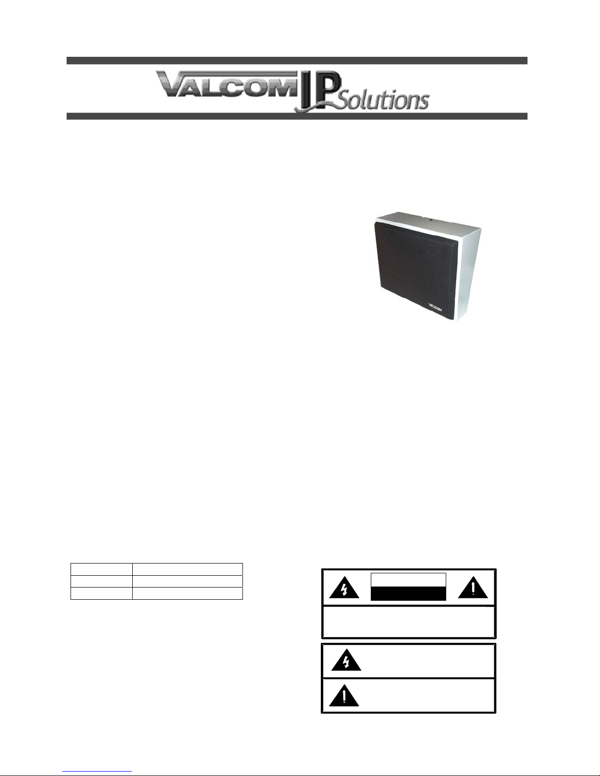
VIP-430A
IP WALL SPEAKER
INTRODUCTION
The VIP-430A IP Wall Speaker enables
handsfree talkback access to a single location
over an IP-based LAN/WAN. This allows a
handsfree talkback extension anywhere on the
network. The speaker levels are electrically
adjusted during setup. The enclosure is made of
steel with a durable gray powder coated finish.
The color of the enclosure can easily be changed
to match any decor. A detachable black clothe
grille is included. A call switch input is provided
for the remote speaker location signaling.
Power is provided to the VIP-430A via a Power
over Ethernet (PoE) switch meeting the 802.3af
specification.
DIMENSIONS/WEIGHT
10.13” H x 12.31” W x 4.63” D
(25.73cm x 31.27cm W x 11.75cm D)
Weight: 4.25 LBS (1.91 kg)
Environment
Temperature: 0 to +40° C
Humidity: 0 to 85% non-precipitating
Packing List
Qty. Item
1 VIP-430A
1 VSP Document
1 947804
INSTALLATION
FCC Information
This equipment has been tested and found to
comply with the limits for a Class A digital
device, pursuant to Part 15 of the FCC Rules.
These limits are designed to provide
reasonable protection against harmful
interference when the equipment is operated
in a commercial environment. This
equipment generates, uses and can radiate
radio frequency energy and if not installed
and used in accordance with the instruction
manual, may cause harmful interference to
radio communications. Operation of this
equipment in a residential area may cause
harmful interference in which case the user
will be required to correct the interference at
his own expense.
Precautionary Designations
CAUTION
RISK OF ELECTRIC SHOCK
DO NOT OPEN
CAUTION: To reduce the risk of electric shock,
Refer se rvic ing to qu alifie d serv ice pers onn e l.
Do not remove cover.
No user serviceable parts inside.
This symbol indicates that dangerous
voltage constituting a risk of electric
sho ck is pre s ent within this un it.
This symbol indicates that there are
imp o rtant op er ating a nd m a inte nance
instruction s in the lit erature accompanyin g
this unit.
Page 2
IMPORTANT SAFETY INFORMATION
CONSIGNES DE SÉCURITÉ IMPORTANTES
1. Read these instructions.
Lisez ces instructions.
2. Keep these instructions.
Conservez ces instructions.
3. Heed all warnings.
Respectez tous les avertissements.
4. Follow all instructions.
Suivez toutes les instructions.
5. Do not use this apparatus near water.
Ne pas utiliser cet appareil près de l'eau.
6. Clean only with dry cloth.
Nettoyer avec un chiffon sec.
7. Do not block any ventilation openings. Install in accordance with the manufacturer’s
instructions.
Ne pas bloquer les ouvertures de ventilation. Installer formément aux instructions du
fabricant.
8. Do not install near any heat sources such as radiators, heat registers, stoves or other
apparatus (including amplifiers) that produce heat.
Ne pas installer à proximité de sources de chaleur telles que radiateurs, registres de
chaleur, poêles ou autres appareils (y compris les amplificateurs) produisant de la chaleur.
9. Do not defeat the safety purpose of the polarized or grounding-type plug. A polarized plug
has two blades with one wider than the other. A grounding type plug has two blades and a
third grounding prong. The wide blade and the third prong are provided for your safety. If
the provided plug does not fit into your outlet consult an electrician for replacement of the
obsolete outlet.
Ne pas contourner le dispositif de sécurité de la fiche polarisée ou de mise à la terre. Une
fiche polarisée possède deux lames dont une plus large que l'autre. Une fiche de terre a
deux lames et une troisième broche de mise à la terre. La lame large et la troisième
broche sont fournies pour votre sécurité. Si la fiche fournie ne rentre pas dans votre prise,
veuillez consulter un électricien pour le remplacement de la prise obsolète.
10.Protect the power cord from being walked on or pinched particularly at plugs, convenience
receptacles and the point where they exit from the apparatus.
11.Only use attachments/accessories specified by the manufacturer.
N'utilisez que des fixations / accessoires spécifiés par le fabricant.
12. Use only with the cart, stand, tripod, bracket or table specified
by the manufacturer or sold with the apparatus. When a cart is
used, use caution when moving the cart/apparatus combination
to avoid injury from tip-over.
Utilisez uniquement avec le chariot, stand, trépied, support ou table spécifié par le
fabricant ou vendu avec l'appareil. Quand un chariot est utilisé, Soyez prudent lorsque
vous déplacez l'ensemble chariot / appareil pour éviter des blessures dues au
renversement.
13. Unplug this apparatus during lightning storms or when unused for a long period of time.
Débranchez cet appareil pendant les orages ou lorsqu'il n'est pas utilisé pendant une
longue période de temps.
14. Refer all servicing to qualified service personnel. Servicing is required when the
apparatus has been damaged in any way. Such as when the power supply cord or plug is
damaged, liquid has been spilled, objects have fallen into the apparatus or the
apparatus has been exposed to rain or moisture and does not operate normally or has
been dropped.
Confiez toute réparation à un personnel qualifié. Une réparation est nécessaire lorsque
l'appareil a été endommagé de quelque façon. Par exemple lorsque le cordon
d'alimentation ou la fiche est endommagé, du liquide a été renversé, si des objets sont
tombés dans l'appareil ou le appareil a été exposé à la pluie ou à l'humidité et ne
fonctionne pas normalement ou s'il est tombé.
MOUNTING
Remove the screw holding the mounting bracket
to the enclosure. Mount the bracket using
appropriate hardware such as #8 pan head
crews. After making the required connections,
reattach the enclosure to the mounting bracket
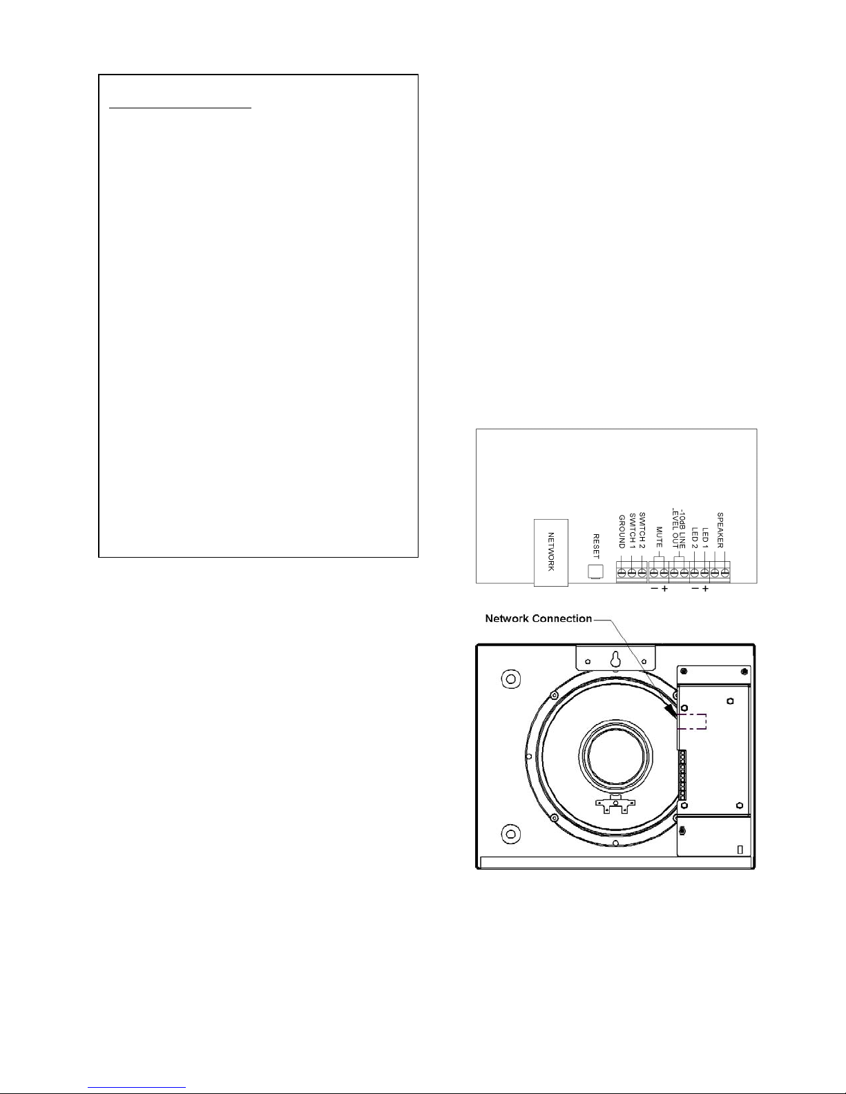
Network Connection
The VIP-430A has one RJ-45 network connector
on the rear panel. Use a standard patch cable to
connect the VIP-430A to an Ethernet switch
providing Power over Ethernet (PoE) meeting the
802.3af specification. If the switch does not
provide power, a mid-span power injector may be
used. (See Figure 1)
MUTE OUT CONNECTION
The Mute Out may optionally be connected to the
mute input of Valcom Classroom audio
management systems in order to suspend locally
originated classroom audio during intercom
announcements.
Call Switch Connection
The VIP-430A provides a call switch input via
screw terminal connections, labeled Switch 1
and Ground.
LED Connection
LED 1 (+) and LED 2 (-) is a current limited
output designed to illuminate an optional LED.
The LED is intended to provide visual indication
of call progress. The LED illumination will flash
when the call switch is pressed and will continue
to flash until the call is answered. The LED
illumination will be solid when a connection to the
unit is established.
-10 dB Line Level Out Connection
The -10dBm Line Level Out may be connected to
up to 40 Valcom Self Amplified Speakers in order
to provide additional sound reinforcement in an
area.
Figure 1. Connections
2 947804
Page 3

Setup
Information specific to your application will need
to be programmed to the VIP-430A using a
computer. The PC used for programming should
be connected to the same subnet as VIP-430A.
Setup will be done using the IP Solutions Setup
Tool. Download the latest version of the free IP
Solutions Setup Tool from Valcom web site at
www.valcom.com/vipsetuptool.
TECHNICAL ASSISTANCE
When trouble is reported, verify power is being
supplied to the unit and there are no broken
connections. If a spare unit is available,
substitute a spare unit for the suspected
defective unit.
Assistance in troubleshooting is available from
the factory. Call (540) 563-2000 and press 1 for
Technical Support or visit our website at
http://www.valcom.com.
Valcom equipment is not field repairable.
Valcom, Inc. maintains service facilities in
Roanoke, VA. Should repairs be necessary,
attach a tag to the unit clearly stating your
company name, address, phone number, contact
person and the nature of the problem. Send the
unit to
Valcom, Inc.
Repair & Return Dept.
5614 Hollins Road
Roanoke, Va. 24019-5056
.
Valcom, Inc. warrants its products only to the original purchaser, for its own use, to be free from defects in materials and workmanship under conditions of
normal use and service for a period of one year from the date of shipment. This Limited Warranty obligation shall be limited to the replacement, repair or
refund of any such defective device within the warranty period, provided that:
1. inspection by Valcom, Inc. indicates the validity of the claim;
2. the defect is not the result of damage, misuse or negligence after the original shipment;
3. the product has not been altered in any way or repaired by others and that factory sealed units are unopened (a service charge plus parts
and labor will be applied to units defaced or physically damaged);
4. freight charges for the return of products to Valcom are prepaid;
5. all units 'out of warranty' are subject to a service charge. The service charge will cover minor repairs (major repairs will be subject to
additional charges for parts and labor).
This Limited Warranty is in lieu of and excludes all other warranties, expressed or implied and in no event shall Valcom, Inc. be liable for any
anticipated profits, consequential damages, loss of time or other losses incurred by the buyer in connection with the purchase, operation,
maintenance, installation, removal or use of the product. The maximum liability of Valcom under this warranty is limited to the purchase price of the
specific Product covered by the warranty.
Disclaimer. Except for the Limited Warranty provided herein, the product is provided “as-is” without any warranty of any kind whatsoever including, without
limitation, any WARRANTY OF MERCHANTABILITY, FITNESS FOR A PARTICULAR PURPOSE OR NON-INFRINGEMENT.
This warranty specifically excludes damage incurred in shipment. In the event a product is received in damaged condition, the carrier should be notified
immediately. Claims for such damage should be filed with the carrier involved in accordance with the F.O.B. point.
VALCOM LIMITED WARRANTY
Headquarters:
Valcom, Inc.
5614 Hollins Road Roanoke, VA 24019-5056
Phone: (540) 563-2000 FAX: (540) 362-9800
3 947804
 Loading...